Wring Throughway
#Parts Shape Q’ty
1
Cascade System Cable 2 sets
2
Manual 1
WARNING
Read this instruction carefully and failure to follow
these instructions exactly could result in a fire or
explosion, serious bodily injury and/or property
damage. Installation must be performed by a qualied
plumber, a licensed gas fitter, or a professional
technician in accordance with all local codes.
Improper installation and operation by an unqualied
person will void the warranty.
CAUTION
1. About Rheem Cascade System
•Cascade System can allows up to 2 units.
•All units within Cascade System must be of the same type.
•Different types cannot work as Cascade System.
■ Included parts on KIT
Before installing this KIT, verify that the parts contained in this KIT with followed table.
2. Overall System Diagram
Electrical Shock Hazard
Do not turn power on until electrical wiring is
nished. Disconnect power before servicing.
Failure to do so may result in death or serious injury
from electrical shock.
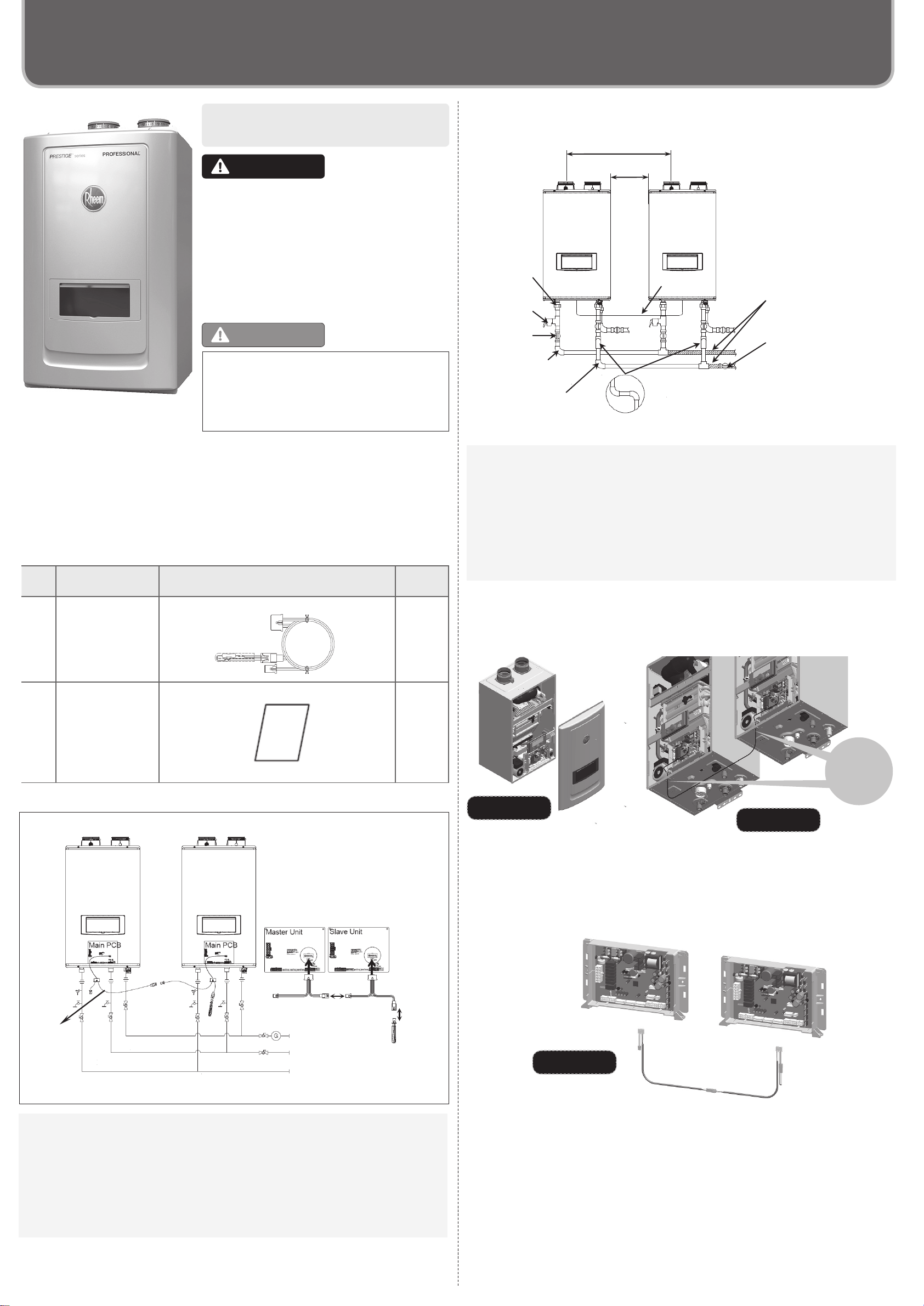
3. Installation
1) Basic Plumbing Diagram
①Turn off both gas and water supply to the water heater. And, turn the power off.
②
Use a hand screwdriver to remove the 4 screws for the front cover. See Figure 1 for
illustration of the front cover on the unit.
③Pass the Cascade System Cord through the wiring throughway at the bottom of the
both units. See Figure 2 for illustration of the throughway location at the bottom of the
units.
④
Plug the wire connector into the ‘Main PCB’ connector inside both each other units.
See Figure 3 for illustration of the Main PCB connector inside units.
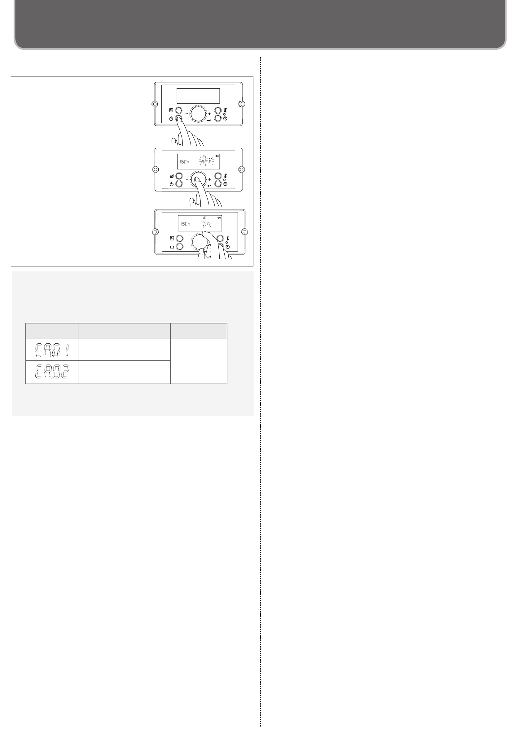
⑤ Set the proper setting on the control panel to activate the Cascade system. For more
detailed conguring, refer to next page on “Setting on the control panel.”
⑥
Close the front cover with secure 4 screws.
2) Installing
[NOTE]
•
The Cascade System Cords are 6 feet (1.8 m) long each. Install the units 2~18” (50~457
mm) apart from each other to ensure the cable will be able to reach between the units.
(See a Basic Plumbing Diagram).
•
If the distance between the two units is too great, not only the cable won’t be able to
reach, but the water temperature may also become unstable because of the difference
in pipe length between the two units.
[NOTE]
All units must be set to the same settings listed below before using in the Cascade
System.
•
Set “on” at [12:Cn] in installer mode (Refer to the next page on the Panel Setting)
•Current Clock Setting.
• Recirculation Timer Setting, if recirculation is used. (Please refer to pages 62-63 in the
U&C Manual)
Figure 1
KIT# : SP20892
Cascade System Installations and Instruction Manual
* Insulate the hot water piping to prevent heat
loss. Insulate and apply heang materials to
the cold water supply piping to prevent heat
loss and freezing of pipes when exposed to
excessively cold temperature
Leave enough clearance around the plumbing
to apply insulaon. It will be necessary to add
bends to the piping to ensure that this
clearance is available
Size the piping to allow for the
maximum flow rate of the units
The backflow preventer is put
up before it diverges
Hot Water
Cold Water
Distance at center : 18~36 in. (489~916 mm)
Union
Pressure
Relief Valve
Shutoff
Valve
Distance on Sides
2~18 in. (50~457 mm)
Cascade System Cable
Figure 1 Figure 2
Figure 3
Cascade
System
Cable
Gas Suppl
Cold Water Su
l
Hot Water Suppl
Connector on PCB detail
ConnectionConnection
Do not connect
anything here