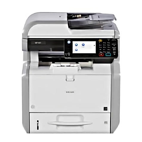
Ricoh MPC 1500sp User manual

MPC 1500sp
Technicians
Troubleshooting Guide
This guide is designed to help you with known issues.
Produced by M. Drage v1.2

White or Coloured Lines
Before completing any of the following, REMOVE AND
CLEAN THE MAINTENANCE UNIT. Pay particular
attention to the wiper area, the roller and first cap.
CLEAN ONLY WITH A CLOTH DAMPENED WITH
WATER - NO CHEMICALS!
Once the above has been completed, move onto head cleaning or flushing.
Select User tools, Maintenance, Head Cleaning or Flushing.
To check which print head is blocked use the Nozzle Check Pattern.
To clean, select CLEAN from the menu - you will have a check box by each
colour. Use the right arrow to select and the down arrow to move onto the
next item.
This is a good one
This shows that the black and cyan print heads are blocked

Sometimes you will have to perform head cleaning more than once to
resolve the issue. If after 4 head cleans, you still have a problem, then try
head flushing. If after this, there is still an issue, then try physically cleaning
the heads.
ONLY USE SPECIALISED HEAD CLEANING CLOTHS
PART NUMBER B2299311
If this is happening regularly there are a few options you can try depending
on when the lines appear.
1. If the symptom occurs when a printout is made after leaving the
machine unused for a long time, make sure the Engine Firmware is
v1.10 or later. This will ensure the head home position is correct, thus
ensuring the heads are capped correctly on the maintenance unit.
2. Make sure the carriage slide is in the correct position. If it is not then,
as previously the heads will not cap correctly, thus drying out. Use
the following guide to check and adjust.
Correct position Incorrect position
Release the lock for the maintenance unit. To do this turn the adjuster clockwise until the
heads of the triangles line up.
Slide the carriage until the small white part in the photo lines up with the hole.

Lift up the carriage unit and insert a small slot screwdriver into the hole and push until
you hear a click.
If the carriage slide is out of position you may get SC202 and/or jams in
areas A/C.
3. If the machine is installed in an environment with a relative humidity
of 15% or less, the ink will dry out quicker, as this is outside of the
machines operational specification and the machine will have to be
moved to a more suitable environment.
4. If the symptom occurs during regular use, then set SP2 508 001
(Exhalation Interval Change) to a value of 1 (every 15 seconds), also
do ONE of the following:
Set bit 6 of SP3 112 004 (print mode setting1) to a value of 1.
Ink mist can easily be generated when using paper with a high surface
impedance such as recycled paper. This mist can clog the nozzles.
Or

Change the setting of SP3 112 004 (print mode setting 4), so that auto
shading is performed more often.
xxxxx000: Default (1 time per approx 300 pages)
xxxxx001:1.3 times
xxxxx002:2 times
xxxxx003:4 times
xxxxx004:10 times. Remember, the more times it cleans, the
slower the print.
5. Each visit, clean the maintenance unit, if you have tried all of the
above you may have to replace the maintenance unit.
Smudged images
This is usually caused when the customer copies or prints onto unsuitable
paper. If the paper is not absorbent enough, the ink cannot dry before the
print head returns. Unfortunately there is no hard and fast rule as to the type
of paper that should be used - it is just a matter of trial and error.
Smudged copies can also occur if the paper is too thick. This product is able
to feed up to 105gms from the trays, 162gms from the bypass and 220gms
from the one sheet bypass. If the customer is using 220gms paper, then the
envelope lever may have to be used (in the down position), this will raise the
print head by about 2mm giving more clearance. Make sure the lever is put
back to normal (up position) as this may cause quality issues when using
normal paper.
Envelope lever

Grainy colour images, colour registration problems,
uneven shading in b/w mode and jagged lines
These issues are usually caused when the print heads are out of alignment.
Grainy Colour Images
Out of adjustment Correctly adjusted
Colour Registration
Out of adjustment Correctly adjusted

Out of Adjustment Jagged Lines
Correctly adjusted
Uneven Shading in B/W Mode
Out of adjustment Correct adjustment
Before any adjustments are made, please ensure that
you have completed the head cleaning successfully.
To do the adjustment, select User tools, to Maintenance, OK, to
Adjustments, OK. The first adjustment that is displayed is Head Position
Adjustment, OK. There are 2 adjustments to be made, Standard and High
Speed. PLEASE DO BOTH .You will be asked to print out the test page.
YOU WILL NEED A4r Paper in the machine, if there is only 1 cassette
you CAN use the bypass.

This is the test pattern produced in standard mode.
You will notice that you have an adjust option on the display. Select this and
the screen will now show the letters A to I with A highlighted.
Look at A on the test pattern above, if the heads are aligned correctly then
the 2 lines circled in red beneath 0 would be straight, the box would also be
light grey. The above pattern is out of adjustment and the correct setting is
+3 (circled in blue).
To change the setting for A, make sure that A is highlighted on the screen
and press OK. In our case press the + key 3 times, + 3 is now on the screen,
press OK. Check and follow the same procedure for all the letters.
Once this is complete, select END and this will take you back to the
maintenance menu, press OK and reprint the test pattern and check it, this
adjustment may have to done again, especially if it was a long way out.
When the standard adjustment is complete, follow the same procedure for
the high speed mode, the test pattern is slightly easier to see.
Once the above is complete, copy your test chart in B/W mode ensuring that
the grey band A is copied.

Look at this band on your copy. If it is uniform, no further action is required.
If, however you have either of the following 2 effects, further fine
adjustment is required.
1 2
To adjust, enter SP mode 3-002-010 (A).Make a note of the value (the
number above the figure in brackets). Also, go to 3-002-017(H) and
3-002-018 (I) and perform the same adjustment.
Complete the calculation I-A=H. As you have one of the above patterns I-A
will not equal H
Example I = 5, A = 3 H = 3 I – A = 2
If the image is the same as diagram 1above then adjust I, e.g. change I to 6
and this will make the calculation correct.
If the image is the same as diagram 2above, then adjust H, e.g. change H to
2.
In some cases when the formula is correct, you may still have a slight
variation, unfortunately there is nothing else you can do.

White or Dark Lines, Even After Head Cleaning Has
Been Performed.
Please ensure that you have completed head cleaning before doing this
adjustment.
To access the set up, press user tools, until Maintenance, OK , until
adjustment, OK until adjustment, OK, until Paper Feed Adjust and
press OK. You will now be asked to print a test pattern again – please ensure
that you have A4R paper loaded in the machine.
This is the test pattern generated. Ideally 0 should have the clearest box and
the straightest lines. In this case, 2 has the clearest box and straightest line.

Select Adjust on the screen to enter -2. Press the – key twice and then Enter.
You will now have a choice to either print the test sheet again to check or
end to finish.
If you still have problems with white or black lines, then you will need to
complete the fine adjustment.
Print the test pattern 15 (Grey Pat 1) with SP4-417-001
If a black or white line occurs in the main scan direction, adjust the paper
feed timing with SP1-922-001 (SubScan:Send Adj).
If you have a black line increase the value by 1
If you have a white line decrease the value by 1
Print the test pattern again and adjust if required.
You may find that you cannot completely get rid of the line, if this is the
case you will have to compromise.
The service manual tells you to increase the value for a white line and
decrease for a black line. THIS IS WRONG, so please follow the
instructions above.
Once all of these adjustments have been completed the print and copy
quality should be good.

The image only appears in the first few centimetres of
the page, sometimes there is no print on the page at all.
This is caused by the second registration sensor misdetecting the edge of the
paper. This can be caused by the following:
a) Letterhead paper used – When Pre printed letterhead paper is used, the
second registration sensor can mistake the print as the belt ( especially
if the pre printed area is a dark colour). To overcome this, change the
feed direction of the paper and ensure that the pre printed area is on
the training edge.
b) Light is reflected from the edge of the printer head cartridge. To
overcome this make sure the engine firmware is at v1.11 or later.
c) The surface of the transport belt is dirty or damaged. Remove the
engine unit and remove the transport belt unit. Examine the belt and if
it is damaged, then replace it B223 3203 - this is a complete unit, as
the belt is not available on its own. If it is dirty, you can clean using a
cloth dampened with WATER ONLY - DO NOT USE
CHEMICALS.
d) The second registration sensor is dirty or faulty - the sensor is located
on the print head. See item 105 (1403 1301)

With the engine unit removed, access to the sensor is quite easy. Remove the
print head cover (this is clipped on) and unclip the sensor. You may find a
small bit of paper stuck on the sensor. Ensure this area is clean.
Excessive amounts of Gel inside the machine, especially
around the print heads and the maintenance unit,
smudges on prints, constant white lines and/or excessive
use of gel.
This is happens when gel leaks from the print heads.
To check if this is happening, remove the maintenance unit and look at the
head caps - the only one that should have any amount of gel on it, is the first
cap. If any of the other caps have significant amounts of gel on them, then
one of the heads could be leaking.
With the maintenance unit removed look at the print heads, if one of them is
leaking you will see droplets of gel forming on the head, also you may find
gel smeared around the heads. No matter how well you clean this area you
will find that after a few prints, it will be just as dirty.
The heads will leak when the seal around the air release valve either
becomes dislodged or is damaged.
Unfortunately, as there are no spare parts available for the print heads, this
means that you will have to fit a complete engine unit (B229 0110).

Jamming in the exit area, usually on A3.
The lead edge of the jammed paper will be just leaving the exit unit and you
will probably hear a buzzing noise as the exit motor stalls.
Remove the exit unit and check the position of the drive belt here.
The drive belt rides up onto the edge of the pulley putting excess strain on
the exit motor. To resolve the issue, release the tension on the belt,
reposition the belt and let the spring set the correct tension.
Connecting a coin box, using the Optional Counter
Interface.
When connecting external coin box equipment to a Pegasus, you must use a
counter interface unit. There is a bulletin (RB229020) on how to connect this
unit. It shows a 6 pin cable connected to CN1 on the interface board, going
to CN117 on the BCU. THIS IS INCORRECT, as you will be supplied
with a different cable. The correct connector is CN3 on the interface unit and
CN149 on the BCU. When the coin box is connected and running, you may
find that when doing more than 1 copy in colour or B/W the incorrect
amount of money is deducted. If this happens, you will need to change a
setting on the coin box. Details on how to make these changes are listed
below. If you have any problems speak to me or Daniel Harrison.
Inepro Coin Box
There is an override key supplied with the Coin Box.
Beside the override key switch are three square buttons.

Button 1 – Function Button
Button 2 – Down Button
Button 3 – Up Button
a) To access the Function Menu: Press and hold in the Function
Button and at the same time turn the Override Switch to On.
b) F0 will now be displayed on the Coin Box Display.
c) Keep pressing the UP Button, until F29 is showing on the
display.
d) Press Button 1 Once (Function Button)
e) Now keep pressing the UP Button, until F45 is displayed.
f) Press the Button 1 Once.
g) F29 is now displayed.
h) Keep pressing the UP Button, until Function 51 is reached.
i) Press Button 1 Once – this takes you into Function 51 and will
show the current default setting of 25.
j) Keep pressing the Down Button till number 5 is displayed.
k) Press Button One (Function Button) - to programme number 5
into Function 51.
l) Now test the Copier in conjunction with the Coin Box.
Setting SP Modes and User Tools.
SP 5 -113 set to Coin Rack
User Tools - System Settings – Key Operator – External Charge Unit
Management.
Other manuals for MPC 1500sp
1
Table of contents
Other Ricoh Copier manuals

Ricoh
Ricoh Aficio 1075 User manual

Ricoh
Ricoh V-C3 Installation guide

Ricoh
Ricoh SAVIN A741 User manual

Ricoh
Ricoh Priport DD 4450 User manual

Ricoh
Ricoh Aficio FT4027 User manual
Ricoh
Ricoh Aficio MP C3000 Series Service manual

Ricoh
Ricoh FT4480 Quick start guide

Ricoh
Ricoh FT5580 User manual

Ricoh
Ricoh A151 User manual

Ricoh
Ricoh MP 1813L User manual

Ricoh
Ricoh Gim-MF1a Quick start guide

Ricoh
Ricoh Ml0 User manual

Ricoh
Ricoh A163 User manual

Ricoh
Ricoh B125 User manual

Ricoh
Ricoh Aficio 1232C User manual

Ricoh
Ricoh 920F User manual

Ricoh
Ricoh SWALLOW 2 User manual
Ricoh
Ricoh Aficio SP 5200S User manual

Ricoh
Ricoh A217 User manual

Ricoh
Ricoh FT2012+ User manual