RIDGID R350RHF User manual

OPERATOR’S MANUAL
MANUEL D’UTILISATION
MANUAL DEL OPERADOR
FULL ROUND HEAD FRAMING NAILER
CLOUEUSE DE CHARPENTIER À TÊTE RONDE
CLAVADORA DE ENTRAMAR PARA CLAVOS DE CABEZA
REDONDA NORMAL
R350RHF
To register your RIDGID
product, please visit:
http://register.RIDGID.com
Pour enregistrer votre
produit de RIDGID,
s’il vous plaît la visite :
http://register.RIDGID.com
Para registrar su producto
de RIDGID, por favor visita:
http://register.RIDGID.com
TABLE OF CONTENTS
****************
General Safety Rules..........................2
Specific Safety Rules ......................3-4
Symbols..............................................5
Glossary of Terms............................6-7
Features..............................................7
Assembly............................................7
Operation.......................................8-11
Maintenance................................12-13
Accessories......................................13
Troubleshooting................................14
Illustrations ..................................15-17
Parts Ordering and
Service ................................Back page
TABLE DES MATIÈRES
****************
Règles de sécurité générales ..........2-3
Règles de sécurité particulières ......3-4
Symboles............................................5
Glossaire.............................................6
Caractéristiques .............................6-7
Assemblage........................................7
Utilisation.......................................8-11
Entretien ......................................12-13
Accessoires ......................................13
Dépannage .......................................14
Illustrations ..................................15-17
Commande de pièces et
dépannage ........................Page arrière
ÍNDICE DE CONTENIDO
****************
Reglas de seguridad generales ..... 2-3
Reglas de seguridad específicas... 3-4
Símbolos............................................5
Glosario de términos .........................6
Características............................... 6-7
Armado..............................................8
Funcionamiento........................... 8-12
Mantenimiento........................... 12-13
Accesorios.......................................13
Solución de problemas....................14
Ilustraciones .............................. 15-17
Pedidos de piezas y
servicio .........................Pág. posterior
WARNING:
To reduce the risk of injury, the
user must read and understand
the operator’s manual before
using this product.
AVERTISSEMENT :
Pour réduire les risques de
blessures, l’utilisateur doit lire
et veiller à bien comprendre
le manuel d’utilisation avant
d’utiliser ce produit.
ADVERTENCIA:
Para reducir el riesgo de
lesiones, el usuario debe leer
y comprender el manual del
operador antes de usar este
producto.
SAVE THIS MANUAL FOR
FUTURE REFERENCE CONSERVER CE MANUEL
POUR FUTURE RÉFÉRENCE
GUARDE ESTE MANUAL
PARA FUTURAS CONSULTAS

2 – English
GENERAL SAFETY RULES
DANGER:
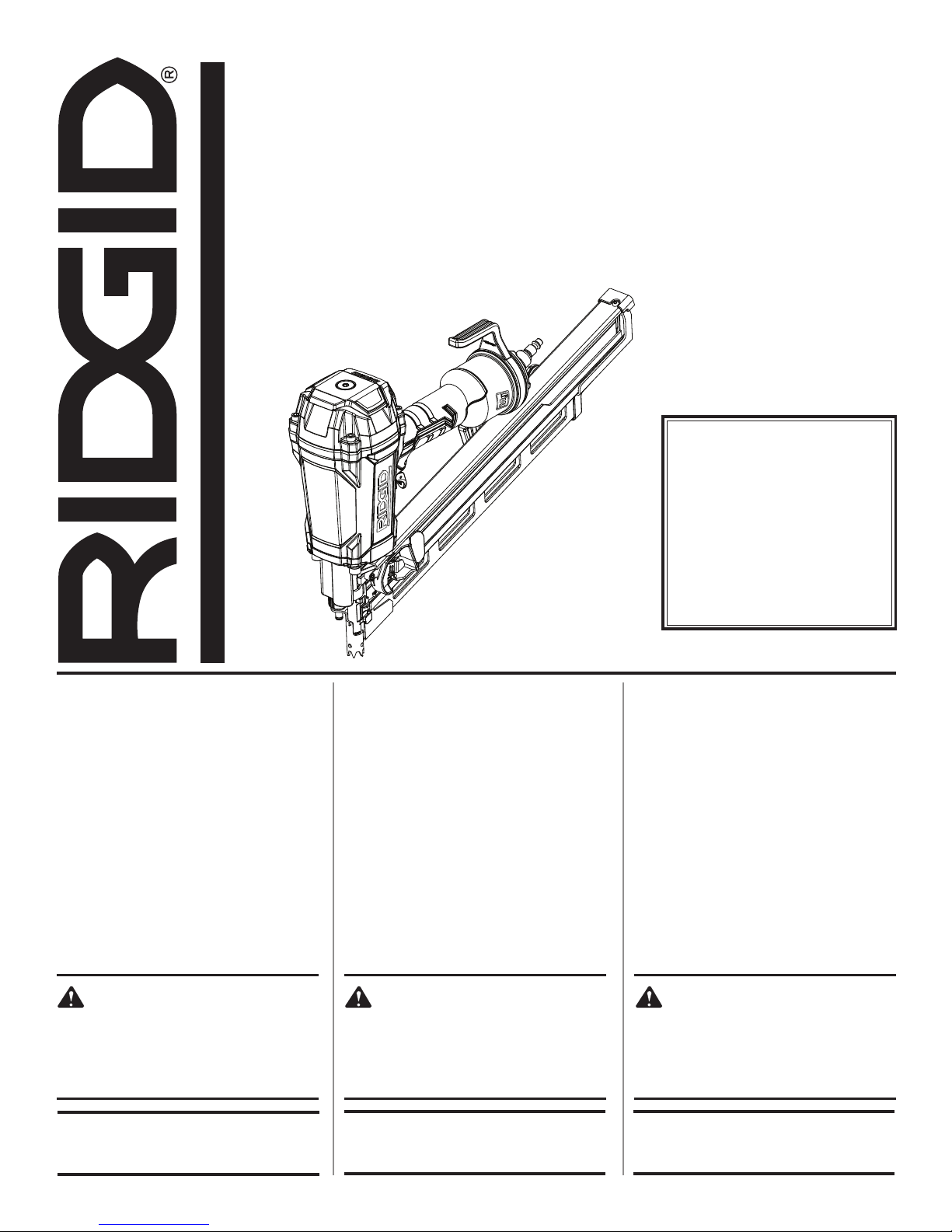
READ AND UNDERSTAND TOOL LABELS AND
MANUAL. Failure to follow warnings could result
in DEATH or SERIOUS INJURY.
SAVE THESE INSTRUCTIONS
WORK AREA
Keep your work area clean and well lit. Cluttered
benches and dark areas invite accidents.
Do not operate power tools in explosive atmospheres,
such as in the presence of flammable liquids, gases,
or dust. Power tools create sparks which may ignite the
dust or fumes.
Keep bystanders, children, and visitors away while
operating a power tool. Distractions can cause you to
lose control.
PERSONAL SAFETY
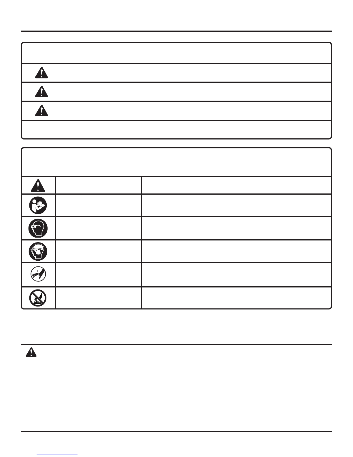
Eye protection which conforms to ANSI specifications
and provides protection against flying particles both
from the FRONT and SIDE should ALWAYS be worn
by the operator and others in the work area when
loading, operating or servicing this tool. Eye protection
is required to guard against flying fasteners and debris,
which could cause severe eye injury.
The employer and/or user must ensure that proper
eye protection is worn. We recommend Wide Vision
Safety Mask for use over eyeglasses or standard safety
glasses that provide protection against flying particles
both from the front and side. Always use eye protection
which is marked to comply with ANSI Z87.1.
Additional safety protection will be required in some
environments. For example, the working area may in-
clude exposure to noise level which can lead to hearing
damage. The employer and user must ensure that any
necessary hearing protection is provided and used by the
operator and others in the work area. Some environments
will require the use of head protection equipment. When
required, the employer and user must ensure that head
protection conforming to ANSI Z89.1-1997 is used.
Stay alert, watch what you are doing and use common
sense when operating a power tool. Do not use tool
while tired or under the influence of drugs, alcohol,
or medication. A moment of inattention while operating
power tools may result in serious personal injury.
Dress properly. Do not wear loose clothing or jewelry.
Contain long hair. Keep your hair, clothing, and gloves
away from moving parts. Loose clothes, jewelry, or long
hair can be caught in moving parts.
Keep fingers away from trigger when not driving fasten-
ers to avoid accidental firing.
Do not overreach. Keep proper footing and balance
at all times. Proper footing and balance enables better
control of the tool in unexpected situations.
Use safety equipment. Always wear eye protection.
Dust mask, nonskid safety shoes, hard hat, or hearing
protection must be used for appropriate conditions.
Do not use on a ladder or unstable support. Stable
footing on a solid surface enables better control of the
tool in unexpected situations.
TOOL USE AND CARE
Do not force tool. Use the correct tool for your
application. The correct tool will do the job better and
safer at the rate for which it is designed.
Do not use tool if trigger does not actuate properly.
Any tool that cannot be controlled with the trigger is
dangerous and must be repaired.
Check operation of the workpiece contact mechanism
frequently. Do not use the tool if the workpiece contact
mechanism is not working correctly as accidental driving
of a fastener may result. Do not interfere with the proper
operation of the workpiece contact mechanism.
Store idle tools out of the reach of children and other
untrained persons. Tools are dangerous in the hands of
untrained users.
Maintain tools with care. Follow maintenance instruc-
tions. Properly maintained tools are easier to control.
Check for misalignment or binding of moving parts,
breakage of parts, and any other condition that may
affect the tool’s operation. If damaged, have the tool
serviced before using. Many accidents are caused by
poorly maintained tools.
Use only fasteners that are recommended for your
model.
Keep the tool and its handle dry, clean and free from
oil and grease. Always use a clean cloth when clean-
ing. Never use brake fluids, gasoline, petroleum-based
products, or any strong solvents to clean your tool. Fol-
lowing this rule will reduce the risk of loss of control and
deterioration of the enclosure plastic.
SERVICE
Tool service must be performed only by qualified
repair personnel. Service or maintenance performed by
unqualified personnel may result in a risk of injury.
When servicing a tool, use only identical replacement
parts. Follow instructions in the Maintenance section
of this manual. Use of unauthorized parts or failure to
follow Maintenance instructions may create a risk of
injury.

3 – English
Know your pneumatic tool. Read operator’s manual
carefully. Learn its applications and limitations, as well
as the specific potential hazards related to this tool. Fol-
lowing this rule will reduce the risk of electric shock, fire,
or serious injury.
Always wear eye protection with side shields marked
to comply with ANSI Z87.1. Failure to do so could result
in objects being thrown into your eyes resulting in pos-
sible serious injury.
Protect your lungs. Wear a face or dust mask if the op-
eration is dusty. Following this rule will reduce the risk of
serious personal injury.
Protect your hearing. Wear hearing protection during
extended periods of operation. Following this rule will
reduce the risk of serious personal injury.
Make sure the hose is free of obstructions or snags.
Entangled or snarled hoses can cause loss of balance or
footing and may become damaged.
Use the tool only for its intended use. Do not discharge
fasteners into open air.
Use the pneumatic tool only for the purpose for which
it was designed.
Do not use hardened nails in this tool.
Use only the fasteners recommended for this tool.
Use of the wrong fasteners could result in poor fastener
feeding, jammed fasteners, and nails leaving the tool at
erratic angles. If fasteners are not feeding smoothly and
properly, discontinue their use immediately. Jammed
and improperly feeding fasteners could result in serious
personal injury.
Never use this tool in a manner that could cause a
fastener to be directed toward anything other than
the workpiece.
Do not use the tool as a hammer.
Always carry the tool by the handle. Never carry the
tool by the air hose.
Do not alter or modify this tool from the original design
or function without approval from the manufacturer.
Always be aware that misuse and improper handling
of this tool can cause injury to yourself and others.
Never clamp or tape the trigger or workpiece contact
in an actuated position.
Never leave a tool unattended with the air hose at-
tached.
Do not operate this tool if it does not contain a legible
warning label.
Do not continue to use a tool that leaks air or does
not function properly.
SPECIFIC SAFETY RULES
OPERATION
Always assume that the tool contains fasteners.
Do not carry the tool from place to place holding the
trigger. Accidental discharge could result.
Always handle the tool with care:
• Respect the tool as a working implement.
• Never engage in horseplay.
• Never pull the trigger unless nose is directed toward
the work.
• Keep others a safe distance from the tool while tool is in
operation as accidental actuation may occur, possibly
causing injury.
Choice of triggering method is important. Check
manual for triggering options.
Do not remove, tamper with, or otherwise cause the
tool operating controls to become inoperable.
Do not operate a tool if any portion of the tool operat-
ing controls is inoperable, disconnected, altered, or
not working properly.
Pneumatic tools are designed for single-hand use. Do
not hold the tool by the front of the magazine. Do not put
hands, head, or other parts of your body near the bottom
of the magazine where the nail exits the tool, as serious
personal injury could result.
Do not point the tool toward yourself or anyone
whether it contains fasteners or not.
Do not actuate the tool unless you intend to drive a
fastener into the workpiece.
Always ensure that the workpiece contact is fully posi-
tioned above the workpiece. Positioning the workpiece
contact only partially above the workpiece could cause
the fastener to miss the workpiece completely and result
in serious personal injury.
Do not drive fasteners near edge of material. The
workpiece may split causing the fastener to ricochet,
injuring you or a co-worker. Be aware that the nail may
follow the grain of the wood, causing it to protrude un-
expectedly from the side of the work material.
Keep hands and body parts clear of immediate work
area. Hold workpiece with clamps when necessary to
keep hands and body out of potential harm. Be sure the
workpiece is properly secured before pressing the nailer
against the material. The workpiece contact may cause
the work material to shift unexpectedly.

4 – English
SPECIFIC SAFETY RULES
Keep face and body parts away from back of the tool
cap when working in restricted areas. Sudden recoil
can result in impact to the body, especially when nailing
into hard or dense material.
During normal use the tool will recoil immediately
after driving a fastener. This is a normal function of
the tool. Do not attempt to prevent the recoil by holding
the nailer against the work. Restriction to the recoil can
result in a second fastener being driven from the nailer.
Grip the handle firmly, let the tool do the work and do not
place second hand on top of tool or near exhaust at any
time. Failure to heed this warning can result in serious
personal injury.
Do not drive fasteners on top of other fasteners or with
the tool at an overly steep angle as this may cause
deflection of fasteners which could cause injury.
AIR SUPPLY AND CONNECTIONS
Do not use oxygen, combustible gases or bottled
gases as a power source for this tool as tool will ex-
plode, possibly causing injury or death.
Do not use with an air compressor which can po-
tentially exceed 200 psi as tool may burst, possibly
causing injury.
The connector on the tool must not hold pressure
when air supply is disconnected. If an incorrect fitting
is used, the tool can remain charged with air after discon-
necting and thus will be able to drive a fastener even after
the air line is disconnected, possibly causing injury.
Air Supply Hose - Hose shall have a minimum working
pressure rating equal to or greater than the pressure from
the power source if a regulator fails, or 150 psi whichever
is greater.
Always disconnect air supply:
• Before making adjustments
• When servicing the tool
• When clearing a jam
• When tool is not in use
• When moving to a different work area, as accidental
actuation may occur, possibly causing injury.
LOADING TOOL
Do not load the tool with fasteners when any one of
the operating controls is activated.
When loading tool:
Never place a hand or any part of body in fastener
discharge area of tool.
Never point tool at anyone.
Do not pull the trigger or depress the workpiece
contact as accidental actuation may occur, possibly
causing injury.
SAVE THESE INSTRUCTIONS
Refer to them frequently and use them to instruct others
who may use this tool. If you loan someone this tool, loan
them these instructions also.

5 – English
SYMBOLS
Some of the following symbols may be used on this tool. Please study them and learn their meaning. Proper interpreta-
tion of these symbols will allow you to operate the tool better and safer.
SYMBOL NAME DESIGNATION/EXPLANATION
Safety Alert Indicates a potential personal injury hazard
Read Operator’s Manual To reduce the risk of injury, user must read and understand operator’s
manual before using this product.
Eye Protection Always wear eye protection with side shields marked to comply with
ANSI Z87.1.
Eye, Ear and Head Protection Always wear other personal protective equipment such as hearing
protection and a hard hat when needed.
Keep Hands Away Keep hands and body away from the discharge area of the tool.
Hot Surface To reduce the risk of injury or damage, avoid contact with any hot
surface.
WARNING:
This product and some dust created by power sanding, sawing, grinding, drilling, and other construction activities
may contain chemicals, including lead, known to the State of California to cause cancer, birth defects, or other
reproductive harm. Wash hands after handling.
Some examples of these chemicals are:
• lead from lead-based paints,
• crystalline silica from bricks and cement and other masonry products and,
• arsenic and chromium from chemically treated lumber
Your risk from exposure to these chemicals varies, depending on how often you do this type of work. To reduce
your exposure, work in a well-ventilated area and with approved safety equipment, such as dust masks that are
specially designed to filter out microscopic particles.
CALIFORNIA PROPOSITION 65
The following signal words and meanings are intended to explain the levels of risk associated with this product.
SYMBOL SIGNAL MEANING
DANGER: Indicates an imminently hazardous situation, which, if not avoided, will result
in death or serious injury.
WARNING: Indicates a potentially hazardous situation, which, if not avoided, could result
in death or serious injury.
CAUTION: Indicates a potentially hazardous situation, which, if not avoided, may result in
minor or moderate injury.
NOTICE:(Without Safety Alert Symbol) Indicates important information not related to an
injury hazard, such as a situation that may result in property damage.

6 – English
GLOSSARY OF TERMS
Activate (operating controls)
To move an operating control so that it is in a position
that allows the tool to be actuated or that satisifes one
requirement for the tool to be actuated.
Actuate (tool)
To cause movement of the tool component(s) intended to
drive a fastener.
Actuation system
The use of a trigger, workpiece contact and/or other
operating control, separately or in some combination or
sequence, to actuate the tool.
• Single sequential actuation
An actuation system in which there is more than one
operating control and the operating controls must
be activated in a specific sequence to actuate the
tool. Additional actuation can occur when a specific
operating control, other than a workpiece contact, is
released and re-activated.
• Contact actuation
An actuation system in which there is more than one
operating control and the operating controls can be
activated in any sequence to actuate the tool. Additional
actuation can occur when any operating control is
released and re-activated.
Air inlet port
In an air tool, the opening to which the compressed air supply
is connected, usually by means of a threaded fitting.
Fastener
A staple, pin, brad, nail, or other fastening device which is
designed and manufactured for use with pneumatic tools.
Jam
An obstruction in the feed or drive areas of the tool.
Maximum air pressure
The maximum allowable pressure of the compressed air, as
specified by the manufacturer, for operating a tool.
Operating control
A control that separately, or as part of an actuation system,
can cause the actuation of a tool.
Trigger
A tool operating control activated by a tool operator’s
fingers.
Workpiece
The intended object into which a fastener is to be driven
by a tool.
Workpiece contact
An operating control element or assembly on the tool
intended to be activated by the material to be fastened.
FEATURES
PRODUCT SPECIFICATIONS
Operating Pressure............................................. 70-120 psi
Magazine Capacity.............................................60-70 nails
Minimum Nail Shank Diameter.............................. 0.113 in.
Maximum Nail Shank Diameter..............................0.148 in.
Air Consumption.............................0.17 ft3/cycle at 100 psi
Air Inlet .............................................................. 3/8 in. NPT
Weighted sound impulse power level..................114.1 dBA
Emission sound pressure level............................104.9 dBA
Weight ........................................................................7.3 lb.

7 – English
FEATURES
ASSEMBLY
WARNING:
Do not use this product if it is not completely
assembled or if any parts appear to be missing or
damaged. Use of a product that is not properly and
completely assembled or with damaged or missing
parts could result in serious personal injury.
WARNING:
Do not attempt to modify this product or create
accessories or attachments not recommended
for use with this product. Any such alteration
or modification is misuse and could result in a
hazardous condition leading to possible serious
personal injury.
If any parts are damaged or missing, please call 1-866-539-1710 for assistance.
KNOW YOUR FRAMING NAILER
See Figure 1, page 15.
The safe use of this product requires an understanding of
the information on the tool and in this operator’s manual as
well as a knowledge of the project you are attempting. Before
use of this product, familiarize yourself with all operating
features and safety rules.
DEPTH-OF-DRIVE ADJUSTMENT
The tool-free depth-of-drive adjustment lets the operator
select precise driving depth of the fastener.
DRY-FIRE LOCKOUT
The dry-fire lockout feature keeps the tool from operating
when fasteners are low in the magazine to prevent missing
fasteners in the nail pattern and extend tool life.
HEX GRIP™
Ergonomic handle with Hex Grip™overmold improves
comfort and grip.
IN-HANDLE AIR FILTER
The self-cleaning in-handle air filter helps keep debris out
to extend the life of the tool.
INTERNAL PISTON CATCH
The internal piston catch delivers consistent driving power.
JAM-CLEARING MECHANISM
The jam-clearing mechanism gives the operator quick access
to the nose of the tool to help clear infrequent jams.
MUFFLER
The muffler reduces noise during operation.
NO-MAR PAD
The no-mar pad prevents marring and denting when using
the tool on softer woods.
QUICK-CONNECT SWIVEL CONNECTOR
The quick-connect swivel connector helps prevent hose
tangles.
RAFTER HOOK
The tool can be hung from a rafter when disconnected and
not in use.
SELECTABLE TRIGGER
The selectable trigger lets the operator choose between
Contact Actuation for higher productivity and Single
Sequential Actuation for precise fastener placement.
TOE-NAILING CLAW
The toe-nailing claw reduces slipping during angled nailing
operations.

8 – English
DANGER:
Do not use oxygen, combustible gases, or bottled
gases as a power source for this tool. The tool will
explode and cause death or serious injury.
WARNING:
Do not allow familiarity with tools to make you
careless. Remember that a careless fraction of a
second is sufficient to inflict severe injury.
WARNING:
Always wear eye protection with side shields
marked to comply with ANSI Z87.1. Failure to do
so could result in objects being thrown into your
eyes resulting in possible serious injury.
WARNING:
Disconnect the tool from the air supply before
leaving the work area, moving the tool to another
location, or handing the tool to another person.
Failure to do so could result in serious personal
injury.
APPLICATIONS
You may use this tool for the purposes listed below:
Framing
Floor Decking
Exterior Decks
Engineered Lumber
Blocking Sub-Assemblies
Fencing
Crate and Box Assembly
Trusses
Pallets and Pallet Repair
Subflooring
WARNING:
Always wear eye protection. Eye protection does
not fit all operators in the same way. Make sure the
eye protection chosen has side shields or provides
protection from flying debris both from the front
and sides.
OPERATION
PREPARING THE TOOL FOR USE
See Figure 2, page 15.
Under normal use conditions, the tool should be lubricated
before connecting the tool to an air supply. Add air tool
lubricant into the air fitting on the tool once daily with minimal
use, or twice a day with heavy use. Only a few drops of oil at
a time is necessary. Too much oil will only collect inside the
tool and will be noticeable in the exhaust cycle.
Before using the tool, check the air compressor gauge to be
sure it is functioning within the proper range of 70-120 psi,
and ensure that the tool is fully operational by completing the
Required Daily Checklist as described later in this manual.
An improperly functioning tool should not be used.
NOTE: Always wear personal protective equipment and
observe all safety instructions when operating this tool.
NO-MAR PAD
See Figure 3, page 15.
The no-mar pad attached to the nose of the tool helps prevent
marring and denting when working with softer woods.
WARNING:
Disconnect the tool from the air supply before
removing or replacing the no-mar pad. Failure to
do so could result in serious personal injury.
The no-mar pad for the framing nailer can be removed by
pulling it open and away from the side of the toe-nailing
claw. To replace the no-mar pad, fit it into place over the
points of the claw.
On-board storage for the no-mar pad is located on the
magazine of the tool.
CONNECTING THE TOOL TO AN AIR SUPPLY
See Figure 4, page 15.
WARNING:
Disconnect the tool from the air supply before
leaving the work area, moving the tool to another
location, or handing the tool to another person.
Failure to do so could result in serious personal
injury.
DANGER:
Do not use oxygen, combustible gases or bottled
gases as a power source for this tool. The tool will
explode and cause death or serious injury.

9 – English
OPERATION
This tool is designed to operate on clean, dry compressed air
at regulated pressures between 70 and 120 psi . The correct
air pressure is the lowest pressure that will do the job.
NOTE: Air pressure that is higher than 120 psi may damage
the tool.
The tool and air hose must have a hose coupling that allows
all pressure to be removed from the tool when the coupling
is disconnected.
WARNING:
Always use a coupling that discharges all the
compressed air in the tool at the time the fitting or
hose coupling is disconnected. Using a coupling
that does not discharge the compressed air could
cause unintended operation and serious personal
injury.
WARNING:
Do not climb rigging or scaffolding while carrying
a tool that is connected to an air hose. Doing so
could result in serious personal injury.
Connect the tool to the air supply with a 1/4 in. female quick
connector. A 3/8 in. female quick connector may be used
in situations where a 1/4 in. supply line is not available. For
maximum tool performance, a 3/8 in. supply line and fittings
are required.
WARNING:
Disconnect the tool from the air supply before
leaving the work area, moving the tool to another
location, or handing the tool to another person.
Failure to do so could result in serious personal injury.
LOADING THE TOOL WITH NAILS
See Figures 5 - 6, page 15.
WARNING:
The tool’s driving mechanism may cycle when the
tool is first connected to the air supply. Always
connect the tool to a pressurized air supply before
loading nails to prevent injury from unintended
cycling. Always make sure the tool’s magazine
is empty at the beginning of each work session,
before connecting to an air supply.
Connect the tool to the air supply.
With the nose of the tool pointed away from you, feed
a strip of nails into the magazine. Be sure the nails are
pointed downward and at the angle shown.
WARNING:
Keep the tool pointed away from yourself and
others when loading nails. Failure to do so could
result in possible serious personal injury.
Slide the pusher all the way to the rear of the magazine.
Release the pusher and allow it to push the nails up to
the driving mechanism. The pusher will stop when it rests
against the end of the nail strip.
NOTE: Do not allow the pusher to snap back into place.
WARNING:
Use only the nails recommended for use with this
tool (refer to the Fastener Guide). The use of any
other nails can result in tool malfunction, leading
to serious injuries.
WARNING:
Never load nails with the workpiece contact or
trigger activated. Doing so could result in possible
serious personal injury.
WARNING:
Do not use nails with a shank smaller than 0.113 in.
diameter. Doing so may cause nails to exit the tool
prematurely through the guide track. Do not use
hardened nails with pneumatic tools. This could
lead to excessive wear of the guide body and allow
nails to exit the back of the guide body, leading to
serious personal injury.
USING THE SELECTABLE TRIGGER
See Figures 7 - 8, page 16.
WARNING:
Never wedge or hold back the workpiece contact
mechanism during operation of the tool. Doing so
could result in possible serious injury.
This tool is shipped from the factory with a selectable trigger
set in the Single Sequential Actuation mode. The selectable
trigger can also be set for Contact Actuation mode.
NOTE: The actuation mode selector is spring loaded and
held in position by locking tab to prevent movement during
operation.

10 – English
OPERATION
SINGLE SEQUENTIAL ACTUATION MODE
Single sequential actuation provides the most accurate
fastener placement.
Disconnect the tool from the air supply.
Depress the actuation mode selector.
Rotate the selector to Position ( ).
Release the actuation mode selector.
WARNING:
The nailer will not function properly if the selector
is not securely seated in either position ( )or
( ). Always ensure the selector is seated properly
to avoid an unexpected fastener discharge and
possible serious personal injury.
Reconnect the tool to the air supply.
Grip the tool firmly to maintain control. Position the nose
of the tool onto the work surface.
Push the tool against the work surface to depress the
workpiece contact.
Squeeze the trigger to drive a fastener.
Allow the tool to recoil away from the work surface as the
fastener is driven.
Always remove your finger from the trigger when the
desired number of fasteners has been driven.
CONTACT ACTUATION MODE
Contact actuation allows very fast repetitive fastener place-
ment.
Disconnect the tool from the air supply.
Depress the actuation mode selector.
Rotate the selector to Position ( ).
Release the actuation mode selector.
Reconnect the tool to the air supply.
Grip the tool firmly to maintain control.
Squeeze and hold the trigger. Push the tool against the
work surface to depress the workpiece contact and drive
a fastener.
Allow the tool to recoil away from the work surface as the
fastener is driven.
Always remove your finger from the trigger when the
desired number of fasteners has been driven.
NOTE: In Contact Actuation Mode, the tool may also be
operated by depressing the workpiece contact against the
surface and squeezing the trigger.
WARNING:
During normal use the tool will recoil immediately
after driving a fastener. This is a normal function
of the tool. Do not attempt to prevent the recoil
by holding the nailer against the work. Restriction
to the recoil can result in a second fastener being
driven from the nailer. Grip the handle firmly, let
the tool do the work, and do not place second
hand on top of tool or near exhaust at any time.
Failure to heed this warning can result in serious
personal injury.
DRY-FIRE LOCKOUT
When the magazine is almost empty of nails, the dry-fire
lockout feature will not allow continued operation.
To resume operation, reload the tool with nails.
SETTING THE AIR PRESSURE
The amount of air pressure required will depend on the size
of the nail and the workpiece material.
Begin testing the depth of drive by driving a test nail into the
same type of workpiece material used for the actual job.
Drive a test nail with the air pressure set at 90-95 psi. Raise
or lower the air pressure to find the lowest setting that will
perform the job with consistent results.
It may be possible to achieve the desired depth with air
pressure adjustments alone. If finer adjustments are needed,
use the depth-of-drive adjustment on the tool.
DEPTH-OF-DRIVE ADJUSTMENT
See Figure 9, page 16.
The depth-of-drive of the nail may be adjusted. It is advisable
to test the depth on a scrap workpiece to determine the
required depth for the application.
To determine depth-of-drive, first adjust the air pressure
and drive a test nail. To achieve the desired depth, use the
depth-of-drive adjustment on the tool.
Disconnect the tool from the air supply.
Turn the depth selector left or right to change the driving
depth.
Reconnect the tool to the air supply.
Drive a test nail after each adjustment until the desired
depth is set.

11 – English
OPERATION
DRIVING NAILS AT AN ANGLE
See Figure 10, page 16.
When driving nails at an angle, make sure that the tool is
pointed away from yourself and others.
When driving nails at an angle, make sure that the tool is
positioned correctly. Driving at an angle that is too steep
may:
• cause the nail to miss the workpiece
• cause the nail to ricochet
• cause the workpiece to splinter, causing the nail to come
back toward the operator.
WARNING:
Never drive a nail at an angle by tilting the tool
forward. This could lead to the fastener missing
the work surface or bouncing off the work surface,
leading to serious injury.
WARNING:
Disconnect the tool from the air supply before
removing nails or clearing a jammed fastener.
Failure to do so could result in serious personal
injury.
REMOVING NAILS FROM THE TOOL
See Figure 11, page 16.
Disconnect the tool from the air supply.
To remove a strip of nails from the tool, press the release
button on the pusher. When released, the pusher will slide
forward.
NOTE: Always keep fingers clear of nail track of magazine
to prevent injury from unintended release of the pusher.
Press down on the nail stop tab near the end of the
magazine and slide the nails over the tab.
Remove the nail strip from the tool.
CLEARING A JAMMED FASTENER
See Figures 12 - 14, page 17.
WARNING:
Disconnect the tool from the air supply before
clearing a jammed fastener. Failure to do so could
result in serious personal injury.
If a nail or fastener becomes jammed in the tool, disconnect
the air hose and keep the tool pointed away from you while
clearing the jam.
Disconnect the tool from the air supply.
Remove fasteners from the tool.
Press the jam-clearing mechanism release button on the
side of the tool.
Slide the jam-clearing mechanism away from the nose of
the tool.
Remove the bent nail, using needle-nose pliers if necessary.
After the nail or fastener has been removed, push the jam-
clearing mechanism toward the nose of the tool until it snaps
back into place over the release button.
NOTE: The jam-clearing mechanism should always be
closed when operating this tool.
If the jam is severe or if the nail is difficult to remove:
Insert a #2 Phillips screwdriver into the driving mechanism.
Tap the screwdriver gently with a hammer. The inserted
screwdriver should push the driver blade back, freeing
the nail jam.
After the nail or fastener has been removed, close the jam-
clearing mechanism and secure it in place.
NOTE: The jam-clearing mechanism should always be
closed when operating this tool.

12 – English
MAINTENANCE
COLD WEATHER OPERATION
For cold weather operation, near and below freezing, the
moisture in the air line may freeze and prevent tool operation.
We recommend the use of air tool oil or permanent antifreeze
(ethylene glycol) as a cold weather oil.
NOTICE:
Do not store tools in a cold weather environment
to prevent frost or ice formation on the tools’
operating valves and mechanisms that could
cause tool failure.
NOTE: Some commercial air line drying liquids are harmful
to “O” rings and seals. Do not use these low temperature
air dryers without checking compatibility.
AIR SUPPLY PRESSURE AND VOLUME
Air volume is as important as air pressure. The air volume
supplied to the tool may be inadequate because of
undersized fittings and hoses, or from the effects of dirt and
water in the system. Restricted air flow will prevent the tool
from receiving an adequate volume of air, even though the
pressure reading is high. The results will be a slow operation
or reduced driving power. Before evaluating tool problems
for these symptoms, trace the air supply from the tool to
the supply source for restrictive connectors, low points
containing water and anything else that would prevent full
volume flow of air to the tool.
REQUIRED DAILY CHECKLIST
See Figures 7 and 8, page 16.
Disconnect the air supply from the tool and remove all
fasteners.
Check all screws, nuts, bolts, and pins on the tool. If
any of these are loose, they must be tightened with the
appropriate size wrench.
Press the workpiece contact against a workpiece to
ensure that it moves smoothly.
With the workpiece contact depressed, pull the trigger.
The trigger should move smoothly, without binding.
Select the single sequential actuation mode ( ).
While the tool is not loaded, connect the appropriate air
supply (at 70 psi) to the tool.
WARNING:
When servicing use only identical replacement
parts. Use of any other parts may create a hazard
or cause product damage.
WARNING:
Always wear eye protection with side shields
marked to comply with ANSI Z87.1. Failure to do
so could result in objects being thrown into your
eyes resulting in possible serious injury.
WARNING:
Disconnect the tool from the air supply before
performing maintenance. Failure to do so could
result in serious personal injury.
GENERAL MAINTENANCE
Avoid using solvents when cleaning plastic parts. Most
plastics are susceptible to damage from various types of
commercial solvents and may be damaged by their use. Use
clean cloths to remove dirt, dust, oil, grease, etc.
WARNING:
Do not at any time let brake fluids, gasoline,
petroleum-based products, penetrating oils, etc.,
come in contact with plastic parts. Chemicals can
damage, weaken or destroy plastic which may
result in serious personal injury.
LUBRICATION
Frequent, but not excessive, lubrication is required for
best performance. Oil for pneumatic fastening tools added
through the air line connection will lubricate the internal
parts. Do not use detergent oil or additives as these oils
will cause accelerated wear to the seals and bumpers in
the tool, resulting in poor tool performance and frequent
tool maintenance.

13 – English
MAINTENANCE
Begin inspection:
• Without pulling the trigger, press the workpiece con-
tact against a workpiece several times. The tool must
not actuate.
• With the workpiece contact not engaged on the
workpiece, point the tool down and away and pull the
trigger several times. Hold the trigger in this position
for a minimum of 5 seconds The tool must not actuate.
• Load fasteners, then press the workpiece contact
firmly against the workpiece and pull the trigger. The
tool must actuate.
• With the workpiece contact still depressed, release
the trigger. The driver must return to its up position.
Disconnect the air supply from the tool and remove all
fasteners.
Select the contact actuation mode ( ).
Reconnect the tool to the air supply.
Begin inspection:
• With the workpiece contact not engaged on the
workpiece, point the tool down and away. Pull the trig-
ger. The tool must not actuate.
• Load fasteners, then fully depress the trigger and push
the workpiece contact against a workpiece. The tool
must actuate.
Disconnect the air supply from the tool and remove all
fasteners.
If the tool successfully meets all the requirements in this
checklist, it is ready for use. Set the trigger on the tool to
operate in the manner that best fits your application.
Set the depth of drive according to the Depth-of-drive
Adjustment section in this manual.
Connect the tool to the air supply and load the proper
fasteners for the desired application. Repeat this checklist
before using the tool each day, or if the tool is dropped
or damaged in any way.
ACCESSORIES
To order parts and maintenance kits, call 1-866-539-1710.
Driver Maintenance Kit....................................................................................................................................079077050701
Overhaul Kit.....................................................................................................................................................079077050702
Oil and Wrench Kit...........................................................................................................................................079077050703
WARNING:
Current attachments and accessories available for use with this tool are listed above. Do not use any attachments
or accessories not recommended by the manufacturer of this tool. The use of attachments or accessories not
recommended can result in serious personal injury.

14 – English
TROUBLESHOOTING
ILLUSTRATIONS START ON PAGE 15
AFTER FRENCH AND SPANISH LANGUAGE SECTIONS.
PROBLEM POSSIBLE CAUSE SOLUTION
Air leak near the top of the tool
or in the trigger area
Inadequate lubrication
Loose screws
Worn or damaged O-rings or seals
Lubricate tool
Tighten screws
Install Overhaul Kit
Air leak near the bottom of the tool Inadequate lubrication
Loose screws
Worn or damaged O-rings or bumper
Lubricate tool
Tighten screws
Install Overhaul Kit
Tool does nothing or
operates sluggishly
Inadequate air supply
Inadequate lubrication
Worn or damaged O-rings or bumper
Verify adequate air supply
Lubricate tool
Install Overhaul Kit
Tool jams frequently Incorrect fasteners
Damaged fasteners
Loose magazine
Dirty magazine
Worn or damaged driver
Verify that fasteners are the correct
size
Replace fasteners
Tighten screws
Clean magazine
Install Driver Maintenance Kit
This product has a 90-Day Satisfaction Guarantee Policy, as well as a
Three-year Limited Warranty.
For Warranty and Policy details, please go to www.RIDGID.com
or call (toll free) 1-866-539-1710.

2 – Français
RÈGLES DE SÉCURITÉ GÉNÉRALES
DANGER :
LIRE ET VEILLER À BIEN COMPRENDRE LES
AUTOCOLLANTS APPOSÉS SUR L’OUTIL ET
LE MANUEL. Le non respect de cet avertissement
pourrait entraîner des BLESSURES GRAVES ou
MORTELLES.
CONSERVER CES INSTRUCTIONS
LIEU DE TRAVAIL
Garder le lieu de travail propre et bien éclairé. Les
établis encombrés et les endroits sombres sont propices
aux accidents.
Ne pas utiliser d’outils électriques dans des
atmosphères explosives, par exemple en présence
de liquides, gaz ou poussières inflammables. Les
outils électriques produisent des étincelles risquant
d’enflammer les poussières ou vapeurs.
Garder les badauds, enfants et visiteurs à l’écart
pendant l’utilisation d’un outil électrique. Les
distractions peuvent causer une perte de contrôle.
SÉCURITÉ PERSONNELLE
Lors du chargement, de l’utilisation ou de l’entretien
de cet outil, l’opérateur et les personnes se trouvant
sur le lieu de travail doivent TOUJOURS porter
un dispositif oculaire à protection FRONTALE et
LATÉRALE, conforme aux normes ANSI. Une telle
protection est requise, car les clous et débris projetés
peuvent causer des lésions oculaires graves.
Il incombe à l’employeur et / ou l’utilisateur de veiller
à ce qu’une protection oculaire adéquate soit utilisée.
Nous recommandons d’utiliser un masque facial à champ
de vision élargi ou des lunettes de sécurité munies
d’écrans latéraux protégeant des débris projetés, plutôt
que des lunettes de vue. Toujours porter une protection
oculaire certifiée conforme à la norme ANSI Z87.1.
Des équipements de protection supplémentaires sont
requis dans certains environnements. Par exemple,
le lieu de travail peut présenter un niveau de bruit
susceptible d’entraîner des lésions auditives. Il incombe à
l’opérateur et à l’utilisateur qu’une protection audidive soit
fournie et utilisée par l’opérateur et les autres personnes
se trouvant sur le lieu de travail. Certains environnements
requièrent le port d’un casque. Il incombe à l’employeur
et / ou l’utilisateur de veiller à ce qu’un casque conforme
à la norme ANSI Z89.1‑1997 soit utilisé.
Rester attentif, prêter attention au travail et faire
preuve de bon sens lors de l’utilisation de tout
outil électrique. Ne pas utiliser cet outil en état de
fatigue ou sous l’influence d’alcool, de drogues ou
de médicaments. Un moment d’inattention pendant
l’utilisation d’un outil électrique peut entraîner des
blessures graves.
Porter une tenue appropriée. Ne porter ni vêtements
amples, ni bijoux. Attacher ou couvrir les cheveux
longs. Garder les cheveux, les vêtements et les gants
à l’écart des pièces en mouvement. Les vêtements
amples, bijoux et cheveux longs peuvent se prendre dans
les pièces en mouvement.
Excepté pour planter des clous, garder les doigts à
l’écart de la gâchette, pour éviter un déclenchement
accidentel.
Ne pas travailler hors de portée. Toujours se tenir
bien campé et en équilibre. Une bonne tenue et un bon
équilibre permettent de mieux contrôler l’outil en cas de
situation imprévue.
Utiliser l’équipement de sécurité. Toujours porter une
protection oculaire. Suivant les conditions, le port d’un
masque antipoussière, de chaussures de sécurité, d’un
casque ou d’une protection auditive est recommandé.
Ne pas utiliser l’outil sur une échelle ou un support
instable. Une bonne tenue et un bon équilibre permettent
de mieux contrôler l’outil en cas de situation imprévue.
UTILISATION ET ENTRETIEN DE L’OUTIL
Ne pas forcer l’outil. Utiliser un outil approprié pour
le travail. Un outil approprié exécutera le travail mieux
et de façon moins dangereuse s’il fonctionne dans les
limites prévues.
Ne pas utiliser l’outil si la gâchette ne fonctionne pas
correctement. Tout outil qui ne peut pas être contrôlé
par la gâchette est dangereux et doit être réparé.
Vérifier le mécanisme de contact de la tête de l’outil
fréquemment. Ne pas utiliser l’outil si le mécanisme
de déclenchement par contact ne fonctionne pas
correctement, car l’éjection accidentelle d’un clou pourrait
se produire. Ne pas empêcher le fonctionnement correct
du mécanisme de contact de la tête de la cloueuse.
Ranger les outils non utilisés hors de portée des
enfants et des personnes n’ayant pas reçu des
instructions adéquates. Dans les mains de personnes
n’ayant pas reçu des instructions adéquates, les outils
sont dangereux.
Entretenir soigneusement les outils. Respecter toutes
les instructions d’entretien. Les outils correctement
entretenus sont plus faciles à contrôler.
Vérifier qu’aucune pièce mobile n’est mal alignée,
grippée ou brisée et s’assurer qu’aucun autre
problème risque d’affecter le bon fonctionnement
de l’outil. En cas de dommages, faire réparer l’outil
avant de l’utiliser de nouveau. Beaucoup d’accidents
sont causés par des outils mal entretenus.
Utiliser exclusivement les clous/agrafes recommandés
pour le modèle d’outil.
Garder l’outil et sa poignée secs, propres et exempts
d’huile ou de graisse. Toujours utiliser un chiffon propre
pour le nettoyage. Ne jamais utiliser de liquide de freins,

3 – Français
RÈGLES DE SÉCURITÉ GÉNÉRALES
Peut ne pas convenir aux outils pneumatiques. Lire
attentivement le manuel d’utilisation. Apprendre les
applications et les limites de l’outil, ainsi que les risques
spécifiques relatifs à son utilisation. Le respect de cette
règle réduira les risques d’incendie, de choc électrique
et de blessures.
Toujours porter une protection oculaire certifiée
conforme à la norme ANSI Z87.1. Si cette précaution
n’est pas prise, des objets peuvent être projetés dans les
yeux et d’autres lésions graves.
Protection respiratoire. Porter un masque facial ou
respiratoire si le travail produit de la poussière. Le respect
de cette règle réduira les risques de blessures graves.
Protection auditive. Porter une protection auditive durant
les périodes d’utilisation prolongée. Le respect de cette
règle réduira les risques de blessures graves.
S’assurer que le flexible n’est ni bloqué, ni accroché.
Un flexible emmêlé ou entortillé peut causer une perte
d’équilibre et être endommagé.
L’outil ne doit être utilisé que pour les applications
pour lesquelles il est conçu. Ne pas décharger des
clous dans le vide.
Cet outil pneumatique ne doit être utilisé que pour les
applicactions pour lesquelles il est conçu.
Ne pas utiliser de clous en acier trempé avec cet outil.
Utiliser seulement les agrafes recommandées pour
cet outil. L’utilisation du mauvais type d’agrafes pourrait
nuire au débit des agrafes et entraîner des bourrages
d’agrafes ainsi que l’éjection des clous de l’outil à des
angles irréguliers. Si le débit des agrafes n’est pas
constant et fluide, cesser de les utiliser sur le champ.
Les bourrages et un débit d’agrafes irrégulier peuvent
occasionner des blessures graves.
Ne jamais utiliser cet outil de façon à ce qu’un clou
puisse être dirigé vers quoi que ce soit d’autre que la
pièce à clouer.
Ne pas utiliser cet outil comme un marteau.
Toujours transporter l’outil par la poignée. Ne jamais
transporter l’outil par le flexible d’air.
Ne pas altérer ou modifier cet outil, ni l’utiliser
pour des fonctions autres que celles prévues, sans
autorisation préalable de son fabricant.
RÈGLES DE SÉCURITÉ PARTICULIÈRES
Ne jamais oublier qu’un usage incorrect ou abusif
de cet outil peut mettre l’opérateur et les autres
personnes présentes en danger.
Ne jamais bloquer la gâchette ou le contact de la
cloususe en position de déclenchement avec du ruban
adhésif ou un quelconque autre système.
Ne jamais laisser l’outil sans surveillance avec le
flexible d’air branché.
Ne pas utiliser cet outil s’il ne comporte pas
d’autocollant d’avertissement.
Ne pas utiliser un outil qui présente des fuites d’air
ou ne fonctionne pas correctement.
UTILISATION
Toujours présumer que l’outil contient des clous.
Ne pas transporter l’outil avec le doigt sur la gâchette.
Un clou pourrait être éjecté accidentellement.
Toujours manipuler l’outil avec précaution :
• Respecter cet outil comme tout équipement de travail.
• Ne pas l’utiliser comme un jouet.
• Ne jamais appuyer sur la gâchette si la tête de l’outil
n’est pas dirigée vers la pièce à clouer.
• Garder toutes les personnes présentes à distance sûre
de l’outil, car un éventuel déclenchement accidentel
pourraît entraîner des blessures.
Le choix de la méthode de déclenchement est
important. Voir les options de déclenchement dans
le manuel.
Ne pas enlever, modifier ou nuire d’une quelconque
façon au bon fonctionnement des commandes de
l’outil.
Ne pas utiliser l’outil si une de ses commandes est
inutilisable, déconnectée, défectueuse ou a été
modifiée.
Les outils pneumatiques sont conçus pour une
utilisation à une main. Ne pas tenir l’outil par la face
avant du chargeur. Tenir les mains, la tête et toute autre
partie du corps à distance du point d’éjection des clous,
près du chargeur, afin d’éviter des blessures graves.
Ne pointer l’outil ni vers soi, ni vers quiconque, qu’il
contienne des clous ou non.
d’essence, de produits à base de pétrole ou de solvants
forts pour nettoyer l’outil. Le respect de cette règle réduira
les risques de perte du contrôle et d’endommagement
du boîtier en plastique.
DÉPANNAGE
Le dépannage des outils doit être confié exclusivement
à un personnel qualifié. Les réparations ou entretiens
effectués par des personnes non qualifiées présentent
des risques de blessures.
Utiliser exclusivement des pièces identiques à celles
d’origine pour les réparations. Se conformer aux
instructions de la section Entretien de ce manuel.
L’usage de pièces non autorisées ou le non respect des
instructions d’entretien peut présenter des risques de
blessures.

4 – Français
RÈGLES DE SÉCURITÉ PARTICULIÈRES
N’actionner l’outil que pour planter un clou dans la
pièce à assujettir.
Toujours s’assurer que la surface de contact est
exactement positionnée sur la pièce à clouer. Un
positionnement seulement partiel de la surface de contact
sur la pièce à clouer peut occasionner des blessures
graves car l’agrafe risque d’être éjectée complètement
à côté de la pièce.
Ne pas planter de clous près du bord du matériau.
La pièce à clouer peut se fendre, causant un ricochet
du clou, qui risque alors de blesser l’opérateur ou une
autre personne présente. Ne pas oublier que le clou peut
suivre le grain du bois et que sa pointe peut ressortir
inopinément par le bord de la planche.
Garder les mains et toutes les parties du corps à
l’écart du point à clouer. Au besoin, assujettir la pièce à
clouer avec des serre‑joint pour garder les mains à l’écart
de la zone dangereuse. S’assurer que la pièce à clouer
est correctement assujettie avant d’appuyer la cloueuse
à sa surface. Le contact de la cloueuse peut causer un
déplacement inopiné de la pièce.
Lors du travail dans des endroits confinés, garder le
visage et le corps à l’écart de l’arrière de l’outil. Un
recul brusque peut projeter la cloueuse contre le corps,
en particulier lors du clouage de matériaux denses.
Durant l’utilisation normale de l’outil, un recul se
produit lorsqu’un clou est planté. Ce recul est normal.
Ne pas essayer de l’empêcher en maintenant l’outil
contre la pièce à clouer. Cela pourrait causer l’éjection
d’un second clou. Tenir la poignée fermement, laisser
l’outil exécuter le travail et ne jamais placer l’autre main
sur le dessus de l’outil ou près de l’échappement. Le
non respect de cette mise en garde peut entraîner des
blessures graves.
Ne pas planter un clou sur un autre ou avec l’outil à
un angle trop prononcé, car le clou pourrait dévier et
blesser quelqu’un.
ALIMENTATION ET CONNEXIONS
PNEUMATIQUES
Ne pas utiliser de l’oxygène ou des gaz combustibles
ou en bouteille pour alimenter l’outil, car celui-ci
pourrait exploser et infliger des blessures graves ou
mortelles.
Ne pas utiliser un compresseur d’air pouvant produire
une pression de plus de 200 P.S.I. car l’outil pourrait
exploser et infliger des blessures.
Le connecteur utilisé sur l’outil ne doit pas maintenir
la pression une fois que l’alimentation pneumatique
a été débranchée. Si un fusible de type incorrect est
utilisé, l’outil peut resté chargé d’air une fois débranché
et éjecter un clou, risquant de blesser quelqu’un.
Tuyau d’alimentation de l’air - Le tuyau doit pouvoir
supporter la pression nominale du compresseur au cas
où un régulateur brise, ou 150 psi, selon la valeur la plus
élevée.
Toujours débrancher l’alimentation pneumatique :
• Avant d’effectuer des réglages
• Lors de l’entretien de l’outil
• Lors du déblocage de l’outil
• Lorsque l’outil n’est pas en usage
• Avant de se déplacer avec l’outil, car un déclenchement
accidentel pourrait entraîner des blessures.
CHARGEMENT DE L’OUTIL
Ne pas charger l’outil lorsque l’une des commandes
de déclenchement est activée.
Lors du chargement de l’outil :
Ne jamais placer une main ou une partie quelconque
du corps devant la tête de l’outil.
Ne jamais pointer l’outil sur qui que ce soit.
Ne pas appuyer sur la gâchette ou sur le mécanisme
de contact, car l’outil pourrait éjecter un clou, risquant
blesser quelqu’un.
CONSERVER CES INSTRUCTIONS.
Les consulterfréquemmentet les utiliser pour instruire
les autres utilisateurs éventuels. Si cet outil est prêté,
il doit être accompagné de ces instructions.

5 – Français
SYMBOLES
Certains des symboles ci‑dessous peuvent être utilisés sur l’outil. Veiller à les étudier et à apprendre leur signification.
Une interprétation correcte de ces symboles permettra d’utiliser l’outil plus efficacement et de réduire les risques.
SYMBOL NAME DESIGNATION/EXPLANATION
Symbole d’alerte de sécurité Indique un risque de blessure potentiel.
Lire manuel d’utilisation Pour réduire les risques de blessures, l’utilisateur doit lire et veiller à bien
comprendre le manuel d’utilisation avant d’utiliser ce produit.
Protection oculaire Toujours porter une protection oculaire avec écrans latéraux certifiée
conforme à la norme ANSI Z87.1.
Protection oculaire, protection
de l’ouïe et casque
Toujours porter des lunettes de sécurité étanches ou munies d’écrans
latéraux ou un masque facial intégral lors de l’utilisation de ce produit.
Garder les mains à l’écart Garder les mains et le corps à l’écart de de la décharge de l’outil.
Surface brûlante Pour éviter les risques de blessures ou de dommages, éviter tout contact
avec les surfaces bûlantes.
Les termes de mise en garde suivants et leur signification ont pour but d’expliquer le degré de risques associé à
l’utilisation de ce produit.
SYMBOLE SIGNAL SIGNIFICATION
DANGER : Indique une situation extrêmement dangereuse qui, si elle n’est pas évitée,
aura pour conséquences des blessures graves ou mortelles.
AVERTISSEMENT : Indique une situation potentiellement dangereuse qui, si elle n’est pas
évitée, pourrait entraîner des blessures graves ou mortelles.
ATTENTION : Indique une situation potentiellement dangereuse qui, si elle n’est pas
évitée, pourraît entraîner des blessures légères ou de gravité modérée.
AVIS :
(Sans symbole d’alerte de sécurité) Indique une information importante
ne concernant pas un risque de blessure comme une situation pouvant
occasionner des dommages matériels.
AVERTISSEMENT :
Ce produit et la poussière dégagée lors du ponçage, sciage, meulage, perçage de certains matériaux et lors
d’autres opérations de construction peuvent contenir des produits chimiques, notamment du plomb qui, selon
l’État de la Californie, peuvent causer le cancer, des anomalies congénitales et d’autres dommages au système
reproducteur. Bien se laver les mains après toute manipulation.
Voici certains exemples de ces produits chimiques :
• le plomb contenu dans la peinture au plomb,
• la silice cristalline contenue dans les briques, le béton et d’autres produits de maçonnerie, ainsi que
• l’arsenic et le chrome contenus dans le bois de construction traité par produits chimiques
Le risque présenté par l’exposition à ces produits varie en fonction de la fréquence de ce type de travail. Pour
réduire l’exposition, travailler dans un endroit bien aéré et utiliser des équipements de sécurité approuvés tels
que masques antipoussières spécialement conçus pour filtrer les particules microscopiques.
PROPOSITION 65 DE L'ÉTAT DE CALIFORNIE

6 – Français
GLOSSAIRE
Activer (commandes de l’outil)
Mettre une commande sur une position déclenchant ou
permettant de déclencher l’outil
Actionner (outil)
Causer le mouvement des pièces conçues pour chasser
le clou.
Système de déclenchement
Gâchette, déclencheur par contact et / ou autre commande
qui, utilisées séparément ou conjointement déclenchent
l’outil.
• Déclenchement par séquence unique
Système de déclenchement comprenant plus d’une
commande et dont les commandes doivent être
actionnées dans un ordre donné pour déclencher
l’outil. Le déclenchement peut être répété lorsqu’une
commande, autre que le déclencheur par contact, est
relâchée, puis actionnée de nouveau.
• Déclenchement par contact
Système de déclenchement comprenant plus d’une
commande et dont les commandes doivent être
actionnées dans n’omporte quel ordre pour déclencher
l’outil. Le déclenchement peut être répété lorsqu’une
commande est relâchée, puis actionnée de nouveau.
Orifice d’entrée d’air
Sur un outil pneumatique, l’ouvreture sur laquelle la source
d’air est connectée, généralement au moyen d’un raccord
fileté.
Pièce de fixation
Agrafe, cheville, clou ou autre pièce de fixation conçue et
fabriquée pour être utilisée pour les outils pneumatique.
Blocage
Obstruction dans le système d’alimentation ou de décharge
de l’outil.
Pression d’air maximum
Pression maximale admissible de l’air comprimé, telle que
spécifiée par le fabricant, pour alimenter un outil.
Commande
Dispositif qui, séparément ou en conjonction avec un
système, peut causer le déclenchement de l’outil.
Gâchette
Commande de l’outil actionnée par le doigt de l’opérateur.
Pièce
Objet dans lequel un clou, une agrafe ou autre pièce de
fixation est enfoncé par l’outil.
Contact de déclenchement
Pièce ou partie de l’outil conçue pour le déclencher par
contact avec la pièce à assujettir.
CARACTÉRISTIQUES
FICHE TECHNIQUE
Pression de service ......................................... 70 à 120 psi
Capacité du magasin .....................................60 à 70 clous
Diamètre de la tige minimum.................................0,113 po
Diamètre de la tige maximum................................ 0,148 po
Consommation d’air............................................................
0,05 m3/cycle (0,17 pi3/cycle) à 100 psi
Entrée d’air ........................................................3/8 po NPT
Niveau acoustique pondéré d’impulsion............ 114,1 dBA
Niveau acoustique pondéré d’émission............. 104,9 dBA
Poids ............................................................ 3,3 kg (7,3 lb)

7 – Français
APPRENDRE À CONNAÎTRE LA CLOUEUSE
Voir la figure 1, page 15.
La sécurité d’utilisation de ce produit exige la compréhension
des informations apposées sur l’outil et contenues dans ce
manuel d’utilisation, ainsi que la connaissance du travail
à exécuter. Avant d’utiliser ce produit, se familiariser avec
toutes ses fonctions et règles de sécurité.
RÉGLAGE DE PROFONDEUR
D’ENFONCEMENT
Ce dispositif permet à l’opérateur d’ajuster précisément la
profondeur d’enfoncement des clous.
SÛRETÉ DE DÉCLENCHEMENT À VIDE
Ce dispositif de sûreté empêche le déclenchement de l’outil
lorsque le magasin est presque vide, pour empêcher les
manques et prolonger la vie utile du moteur.
HEX GRIP™
Poignèe ergonomique avec surmoulage Hex Grip™pour un
plus grand confort et une meilleure prise.
FILTRE À AIR DANS LA POIGNÉE
Ce filtre autonettoyant empêche la pénétration de débris et
prolonge la vie utile de l’outil.
BUTÉE DE PISTON INTERNE
Cette butée assure la régularité d’enfoncement des clous.
MÉCANISME DE DÉBLOCAGE
La mécanisme de déblocage permet à l’utilisateur d’accéder
rapidement à la nez de l’outil pour dégager les pièces qui
peuvent se coincer à l’occasion.
SILENCIEUX
Réduit le bruit de fonctionnement.
COUSSINET DE PROTECTION
Le coussinet de protection empêche de marquer ou d’érafler
les bois tendres.
CONNECTEUR RAPIDE PIVOTANT
Ce connecteur aide à empêcher les entortillements
du flexible.
CROCHET À CHEVRON
L’outil peut être suspendu à un chevron lorsqu’il est
débranché et pas utilisé.
GÂCHETTE À SÉLECTEUR
Cette gâchette permet à l’opérateur de choisir entre le
déclenchement par contact, pour un rendement accru ou
le déclenchement à séquence unique pour un placement
précis des clous.
GRIFFE DE CLOUAGE EN BIAIS
Cette griffe réduit le glissement lors du clouage en biais.
CARACTÉRISTIQUES
ASSEMBLAGE
Si des pièces sont manquantes ou endommagées, obtenir de l’aide en composant le 1‑866‑539‑1710.
AVERTISSEMENT :
Ne pas utiliser le produit s’il n’est pas complètement
assemblé ou si des pièces semblent manquantes
ou endommagées. L’utilisation d’un produit
dont l’assemblage est incorrect ou incomplet ou
comportant des pièces endommagées ou absentes
représente un risque de blessures graves.
AVERTISSEMENT :
Ne pas essayer de modifier cet outil ou de créer
des accessoires non recommandés pour ce
produit. De telles altérations ou modifications sont
considérées comme un usage abusif et peuvent
créer des conditions dangereuses, risquant
d’entraîner des blessures graves.
Other manuals for R350RHF
3
Table of contents
Languages:
Other RIDGID Nail Gun manuals

RIDGID
RIDGID R175RND User manual

RIDGID
RIDGID R350RHF User manual

RIDGID
RIDGID R350PNA User manual

RIDGID
RIDGID R250AFA User manual

RIDGID
RIDGID R350RHD User manual

RIDGID
RIDGID R213BNF User manual

RIDGID
RIDGID R09892 User manual

RIDGID
RIDGID R350PNF User manual

RIDGID
RIDGID R175RNF User manual

RIDGID
RIDGID R350CHD User manual

RIDGID
RIDGID R250SFA User manual

RIDGID
RIDGID R09895 User manual

RIDGID
RIDGID R213BNE User manual

RIDGID
RIDGID R350CHA User manual

RIDGID
RIDGID R250SFA User manual

RIDGID
RIDGID R175RND User manual

RIDGID
RIDGID R250AF18 User manual

RIDGID
RIDGID R09890VN User manual

RIDGID
RIDGID R250AFE User manual

RIDGID
RIDGID R350CHE User manual