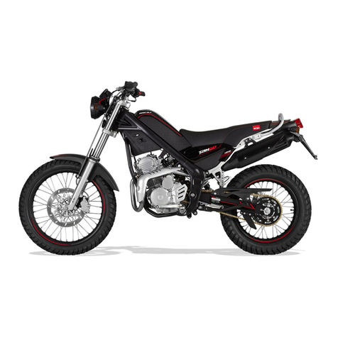
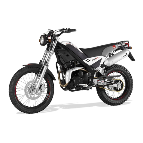
RIEJU TANGO 125 User manual

TANGO
TANGO
125
125
Chassis workshop manual

1
Chassis
EN
G
LI
S
H
Index
INTRODUCTION
MANUAL UPDATES
SYMBOLOGY USED IN THE MANUAL
ABBREVIATIONS USED IN THE MANUAL
GENERAL WORK RULES
RECOMMENDATIONS
TO KNOW THE MOTORCYCLE
MAINTENANCE OPERATIONS
SPECIFICATIONS AND TECHNICAL CHARACTERISTICS
UNPACKING
“AESTHETIC” CONTROL
IDENTIFICATION DATA
SAFETY TAG
IDENTIFICATION OF THE MAIN PARTS
CONTROLS AND INSTRUMENTS
KEYS
STEERING LOCK
SIDE STAND
DASHBOARD
TYRES
PRESSURE CONTROL
FUEL TANK
TRANSMISSION OIL
BRAKE OIL
ADJUSTMENT OF THE MINIMAL INTERVAL OF TURN
TENSION ADJUSTMENT OF THE TRANSMISSION CHAIN
6
7
8
9
10
14
14
18
18
18
18
19
20
20
20
21
21
22
22
22
23
24
24
25

EN
G
LI
S
H
Chassis
2
Index
DISASSEMBLY
1. SEAT
2. LATERAL COVER
3. FRONT LATERAL COVER
4. PILLION SEAT
5. MUFFLER
6. EXHAUST
7. BATTERY
8. REAR DIRECTION INDICATORS
9. TAILLIGHT
10. AIR FILTER
11. REGULATOR
12. COMPONENTES ELÉCTRICOS
13. CDI UNIT
14. FILTER BOX
15. SHOCK ABSORBER
16. GEAR LEVER
17. FUEL TANK
18. CARBURETTOR
19. SIDE STAND
20. FRONT MUDGUARDS
21. ENGINE
22. FRONT DIRECTION INDICATORS
23. HEADLIGHT
24. DASHBOARD
25. FRONT BRAKE PUMP
26. CLUTCH LEVER
27. HANDLEBAR
28. FRONT BRAKE PIN
29. REAR BRAKE PIN
30. FRONT WHEEL
31. ODOMETER SENSOR
32. FRONT BRAKE DISC
33. STEERING
34. FRONT FOOTREST
28
28
28
29
29
30
31
31
32
32
33
33
33
34
35
35
36
36
37
37
38
39
39
40
41
41
42
42
42
43
43
43
44
44

3
Chassis
EN
G
LI
S
H
Index
35. REAR FOOTREST
36. REAR BRAKE LEVER
37. DRIVE CHAIN GUARD
38. TRANSMISSION CHAIN
39. REAR BRAKE PUMP
40. KICK-STARTER
41. SWING ARM
42. TORQUE
44
45
45
45
46
46
47
47

5
EN
GLISH
Introduction
Introduction

EN
G
LI
S
H
Introduction
Chassis
6
This workshop manual contains the main electromechanical checks, as well as the essential general
checks and the fitting of components supplied separately, designed to prepare the factory-new mo-
ped for delivery.
It is very important to adhere strictly to the instructions set out in the manual. Interventions carried
out superficially, or worse still, omitted entirely, may result in personal injury to the user, damage to
the machine, etc., or may simply result in disagreeable complaints.
N.B.: Rieju, S.A. reserves the right to make changes at any time, without prior notification.
For any enquiry, or for further complimentary information, please call the Rieju S.A. After-
sales Service.
MANUAL UPDATES
Updates will be sent within a reasonable period of time. Each new CD-Rom will update previous
information.
The contents list will be updated if the modifications and/or variations in the pages affect the ability
to consult the manual.
IMPORTANT! This series of workshop manuals should be considered as work instruments in the-
mselves and can only maintain their “value” over time if they are kept constantly up to date.

Introduction
7
Chassis
EN
G
LI
S
H
SYMBOLOGY USED INTHE MANUAL
CAUTION! Recommendations and precautions regarding rider safety and mo-
tor vehicle integrity.
WARNING!
Situations entailing the risk of personal injury to maintenance or repair mecha-
nics, other workshop personnel or third parties, or damage to environment,
vehicle or equipment.
FIRE HAZARD
Indicates operations which may constitute a fire hazard.
RISK OF EXPLOSION
Indicates operations which may constitute a risk of explosion.
TOXIC
Indicates a possibility of intoxication or inflammation of the upper respiratory
tract.
MECHANICAL MAINTENANCE
Operations to be performed only by an expert mechanic.
ELECTRICAL MAINTENANCE
Operations be performed only by an expert electrical / electronic technician.
NO!
Operations to be absolutely avoided.
SERVICE MANUAL
Indicates information which may be obtained by referring to said manual.
SPARE PARTS CATALOGUE
Indicates information which may be obtained by referring to said catalogue.
TOXIC
TOXIC
TOXIC

EN
G
LI
S
H
Introduction
Chassis
8
Note:
The letterTr in the illustrations refers to retaining or adjusting screws.The
number following this letter refers to the number of the same type of screw
in the unit or component described and illustrated. Letters not followed by
a number indicate a single screw . In case of different screws being referred
to in the illustration, the letterTr is followed by a number and a small letter
, for instance: (Tr4a).
Unless otherwise specified, units and components are reassembled by pro-
ceeding in the reverse order of removal.
F
Pr Tr
P
Ap
S
Es
T
Tr
ABBREVIATIONS USED INTHE MANUAL
Figure
Tightening torque
Page
Paragraph
Section
Diagram
Table
Screw

Introduction
9
Chassis
EN
G
LI
S
H
GENERAL WORK RULES
The advice, recommendations and warnings given hereafter are aimed at ensuring
maximum work safety as well as at considerably reducing the risk of accidents, personal
injury, equipment damage and idle times. They should therefore be strictly adhered to.
ADVICE:
Only use quality tools and equipment.
Only use equipment conforming to EU Directives for lifting the vehicle.
During operations, always keep tools and equipment at hand, possibly laying them out
according to the sequence in which they are to be used. Absolutely avoid putting them on
the vehicle itself, out-of-sight or in poorly accessible places.
Always keep the work area clean and tidy.
When tightening screws or nuts, start with the larger diameter or inner fasteners, and
tighten them in progressive “pulls” in accordance to a “criss-cross” pattern.
Preferably use open-end box wrenches by “pulling” and not “pushing”.
Adjustable wrenches (F-1) should only be used in case of emergency, i.e. when a properly
sized wrench is not available. They should preferably not be used as the movable jaw tends
to open thus risking damaging or not properly tightening the bolt to the correct torque. In
any case, when using an adjustable wrench, take care to proceed as shown in Figure 1.
Except for occasional customers, always make out and deliver to the customer a work
sheet specifying the operations performed, with notes as to any future checks eventually
required.
F-1
•
•
•
•
•
•
•
•
•

EN
G
LI
S
H
Introduction
Chassis
10
F-2 F-3
RECOMMENDATIONS
Before carrying out any operation on the vehicle, wait for all parts to cool down.
For operations requiring two mechanics, make sure that the various steps to be performed by
each of them are clearly defined and coordinated beforehand.
Make sure that each component has been properly fitted before proceeding with the next
one.
Lubricate all parts (where applicable) before reinstalling them.
Gaskets, O-rings, circlips and split pins must be replaced at every refitting.
The torque settings specified in the manuals refer to the “final torque”, which must be attai-
ned progressively by steps.
Loosen and tighten aluminium alloy parts (covers) only after the engine has fully cooled
down.
Only use screwdrivers with sizes suitable to the screws to be loosened or tightened.
Work in a comfortable position and ensure that the vehicle is stable.
Never use a screwdriver as a lever or chisel.
Never use pincers to loosen or tighten screws or nuts because, in addition to not
providing a sufficient clamping force, they may also damage the screw head or nut
hexagon.
Never tap the wrench with a hammer or other similar tools to loosen or tighten
screws and nuts (F. 2).
Never attempt to increase the lever arm by fitting a tube into the wrench (F-3).
•
•
•
•
•
•
•
•
•
•
•
•
•

Introduction
11
Chassis
EN
G
LI
S
H
Never use open flames for any reason.
Never leave open containers or containers not suitable for holding fuel in passageways,
close to heat sources, etc
Never use petrol to clean the vehicle or the floor of the workshop. Always use low flash
point solvents to clean the vehicle components.
Never suck from or blow into the fuel pipe.
When welding, make sure that there are no flammable liquids in the vicinity. Always re-
move the tank, even if completely empty, and disconnect the negative cable (-) from the
battery.
Never leave the engine running in closed or poorly ventilated areas.
Before any servicing, make sure that the motorbike is perfectly stable.
The front wheel should preferably be anchored to the equipment (A/F-4) integral with the
lifting board.
F-4

13
EN
GLISH
To know the motorcycle

EN
G
LI
S
H
Rieju chassis
Chassis
14
SPECIFICATIONS AND TECHNICAL CHARACTERISTICS
1ST SERVICE
AT 1.000 KM.
2ND SERVICE
AT 3.000 KM.
MAINTENANCE OPERATIONS
SERVICE EACH
5.000 KM
Brake system checking
Transmission oil level checking
Chain tension and wear inspection
Suspension control
Controls and cables checking, adjustment and grease
Wheel spoke tension and wheel off-centre inspection
Air filter cleaning and grease
Carburettor checking and adjustment
Spark plug checking and adjustment or change
Screws and chassis nut control – plastics
Electrical system checking
Segments wear control
Exhaust system checking
Terminals and battery conditions checking
·
·
·
·
·
·
·
·
·
·
·
·
·
·
·
·
·
·
·
·
·
·
·
·
·
·
·
·
·
·
·
Dimensions
Overall length
Overall width
Overall height
Seat height
Wheelbase
Minimum ground clearance
Weight
Dry 101 kg.
Type
Transmission
Make
Cylinder arrangement
Cylinder capacity
Bore x stroke
Compression ratio
Starting system type
Lubrication system
4-stroke SOHC
5 speeds
YAMAHA
Monocylindrical, forward-inclined cylinder
123,7 c.c.
54 x 54 mm.
10:1
Kick-starter and electric starter
Wet sump
1995 mm.
800 mm.
113 0 m m.
790 mm.
1305 mm.
250 mm.
Engine
Change Change

Rieju chassis
15
Chassis
EN
G
LI
S
H
Transmission Oil
Type
Quantity
CASTROL SAE 20W-50 API, “SH” or
high-grade
Air Filter
Wet type foam rubber cartridge
Fuel
Type
Fuel tank capacity
Unleaded petrol
5,5 L.
Carburettor
Mikuni / VM 20
Spark plug
Type
Electrodes gap
CR7HSA / NGK or U22FSR-U / THICK
0,6 - 0,7 mm.
Clutch type
Wet, multiple-disc
Primary transmission
Clutch crown
Stroke pinion
Transmission ratio
Z = 19
Z = 69
1: 3,57
Secondary transmission
Start engine pinion
Pulling plate
Transmission ratio
Chain
Z = 14
Z = 48
1: 3,42
428 RN8 x 126 steps
Speed
1ª
2ª
3ª
4ª
5ª
Primary shaft
Z = 14
Z = 18
Z = 19
Z = 22
Z = 24
Secondary shaft
Z = 37
Z = 32
Z = 25
Z = 23
Z = 21
Gear ratio
1: 2,64
1: 1,78
1: 1,32
1: 1,05
1: 0,88
Start ratio
1: 9,42
1: 6,35
1: 4,71
1: 3,74
1: 3,14
GEAR CHANGE

EN
G
LI
S
H
Rieju chassis
Chassis
16
Brakes
Front
Rear
Disc Ø 260 mm.
Disc Ø 200 mm.
Tyres
Front
Rear
Bridgestone 90/100-19” 55P with tube
Bridgestone 120/90-16” 63P with tube
Electric equipment
Ignition system
Generator
Battery
Fuse
C.D.I.
Magneto generator AC 120 w
12 V - 5,5 Ah
10 Amp
Bulb voltage and wattage
Headlight
Taillight
Dashboard
Indicators
Odometer lighting
12V 55/60W H4
12V 21/10W
12V 1,2W
12V 10W
Led
Suspension
Front
Rear
Telescopic fork
Bar Ø 37 mm
340 cc CASTROL SAE 15Wper bar
Gas damper
B
ra
k
e
s

EN
G
LI
S
H
Rieju chassis
Chassis
18
UNPACKING
Unpack the motorcycle following the indications appearing on the same packaging, after
that it should be thrown according to current regulations.
“AESTHETIC” CONTROL
Control visually that all the components of plastic material are correctly assembled and
that the motorcycle does not show any scratch, mark, etc.
IDENTIFICATION DATA
Engine identification number
The data for identifying the engine (A/F -1) are on the right sump.
Vehicle identification number
The identification number of the motorcycle (B/F -2) is stamped on the steering pipe.
F-1 F-2
B
A
SAFETYTAG
It contains the identification data of the mo-
torcycle according to the 97/24/CE guidelines.
It is absolutely essential to indicate the identi-
fication data of the motorcycle when ordering
spare parts.
This tag should not be substituted either mo-
dified.
•
•
•
F-3

Rieju chassis
19
Chassis
EN
G
LI
S
H
IDENTIFICATION OFTHE MAIN PARTS
(Left side)
1. Headlight
2. Rear-view mirror
3. Fuel tank
4. Battery
5. Rear direct. indicators
6. Side stand
7. Gear pedal
8. Front direct. indicators
IDENTIFICATION OFTHE MAIN PARTS
(Right side)
9. Grab bar
10. Air filter box
11. Fuel tank cap
12. Rear brake pedal
13. Passenger footrest
14. Number plate light and
plate holder
13
7
4
F-4
F-5
6
8
5
2
910
12
13
11
14

EN
G
LI
S
H
Rieju chassis
Chassis
20
1. Rear-view
2. Clutch lever
3. Dashboard
4. Main switch
5. Front brake pump
6. Front brake control
2 4 6
51
7
KEYS
• The motorcycle is provided with two numeric code keys which allow:
- To establish start ignition
- To turn on the lights
- To lock the steering
STEERING LOCK
• Activate: With the handlebar turned to the left, get the key thorough into the lock and
then turn it to the left.
• Deactivate: Turn the key to the right.
3
8
91011121314
CONTROLS AND INSTRUMENTS
7. Accelerator grip
8. Start switch
9. Fuel tank cap
10. Stop switch
11. Lights switch (dipped and
full-beam headlights)
12. Indicator switch
13. Start lever
14. Horn switch
F-6

Rieju chassis
21
Chassis
EN
G
LI
S
H
DASHBOARD
1
3
2
4
5
F-8
F-7
1-
2-
3-
4-
5-
“N” neutral gear warning light
This warning light lits when the transmission is in the neutral gear position.
Oil level warning light
This warning light lits when the oil level is low.
Coolant temperature warning light
This warning light lits when the temperature of the coolant is too much high. If this hap-
pens, stop the engine immediately.
Steering warning light
This warning light twinkles when the steering switch moves towards the left or the right.
Warning light of the full-beam headlights
This indicator lits when the full-beam headlights are in use.
6
SIDE STAND
• Make sure the lateral rest is well fixed and
it moves correctly likewise it is advisable to
check frequently the hold-up system, made up
of drive springs.

EN
G
LI
S
H
Rieju chassis
Chassis
22
TYRES
Dimensions
Front: 90/100-19” 55P with tube
Rear: 120/90-16” 63P with tube
PRESSURE CONTROL
The pressure of the tyres must be controlled and regulated with the “tyres at room tem-
perature”.
FUELTANK
Unscrew the cap and refuel the tank paying attention not to pass the limit; if after filling
some petrol residues are showed on the motorcycle, wipe them off immediately.
Use normal unleaded petrol.
Fuel tank capacity: Total: 5,5 litres
FRONT
REAR
1,7 kg / cm2
2,0 kg / cm2
F-10
Bar
F-9
FRONT
REAR
Position
Other manuals for TANGO 125
2
Table of contents
Other RIEJU Motorcycle manuals

RIEJU
RIEJU RS3 50 User manual

RIEJU
RIEJU MARATHON 250 User manual

RIEJU
RIEJU MRX 125 User manual

RIEJU
RIEJU MRT 50 Instruction manual

RIEJU
RIEJU CENTURY 125IE User manual

RIEJU
RIEJU TANGO 250 User manual

RIEJU
RIEJU Marathon 125 PRO User manual

RIEJU
RIEJU MRX User manual

RIEJU
RIEJU Marathon 125 PRO User manual

RIEJU
RIEJU tango 50 User manual

RIEJU
RIEJU TANGO 250 Instruction manual

RIEJU
RIEJU MRT 50 User manual

RIEJU
RIEJU MRT 50 User manual

RIEJU
RIEJU Tango 125 E4 User manual

RIEJU
RIEJU Marathon 450 User manual

RIEJU
RIEJU Strada 125 ie User manual

RIEJU
RIEJU RS3 Naked 50 User manual

RIEJU
RIEJU TANGO 125 User manual

RIEJU
RIEJU KOSO User manual

RIEJU
RIEJU TANGO 125 User manual