G750 Rev.2 -06/10/2002
STEP-BY-STEP PROCEDURE
1) Remove the burner from the carton, taking care not to lose any of the supplied accessories, and check for
signs of physical damage.
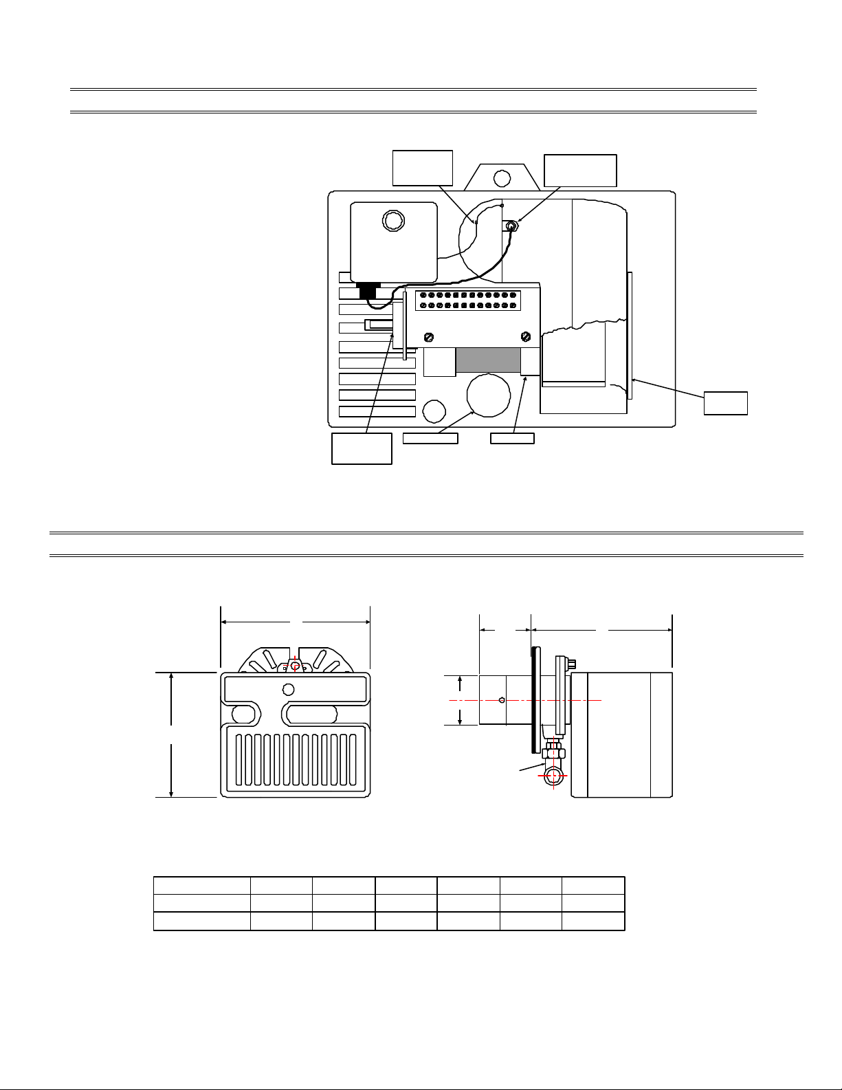
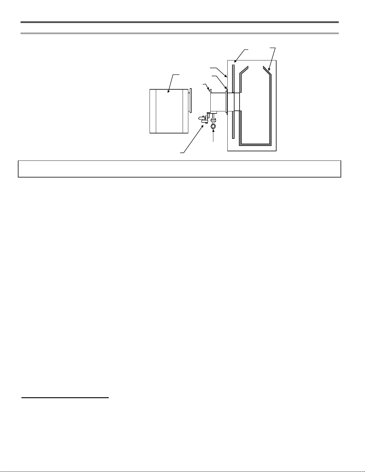
2) Bolt the burner to furnace/boiler. Be sure to install the supplied mounting gasket. Ensure that the burner
is level and that the combustion head is centered in the boiler/furnace port. A spirit level placed across the
cover will give you a good level. Refer to page 7 for position of combustion head relative to the chamber.
3) Check that the gas train is tight and make your connections to the incoming gas supply.
a) A sediment trap must be provide at the gas connection inlet to the burner gas
train.
b) If not already installed, a manual shutoff valve must be supplied. This valve must be upstream of
the burner/supply connection.
c) A 1/8 NPT plugged tapping must be installed immediately upstream of the
Burner/supply connections and must be accessible for a test gauge.
d) If required by local codes, provide gas vent lines at the gas regulators and
And valve (Riello gas trains are equipped with vent limiting orifices).
NOTE: Details of sediment trap, manual gas valve and test point can be found in installation of sediment trap
and burner supply section.
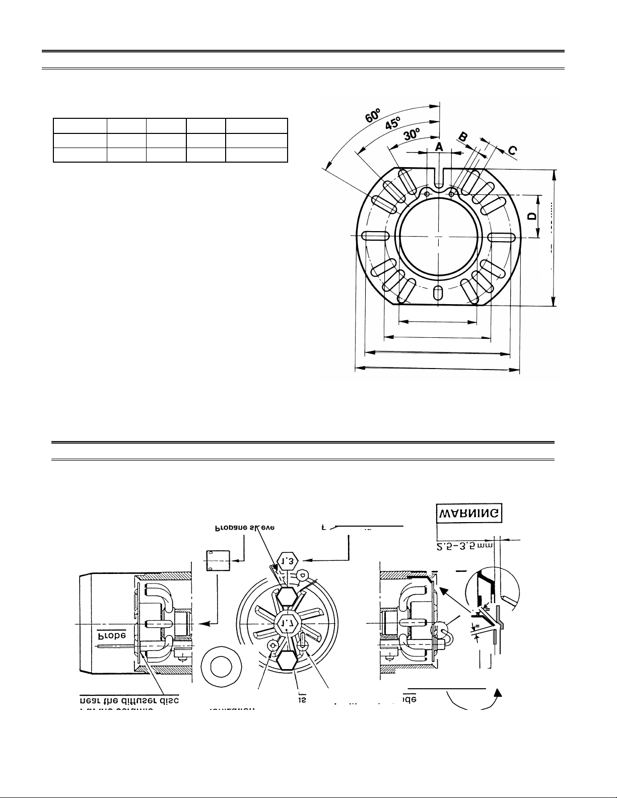
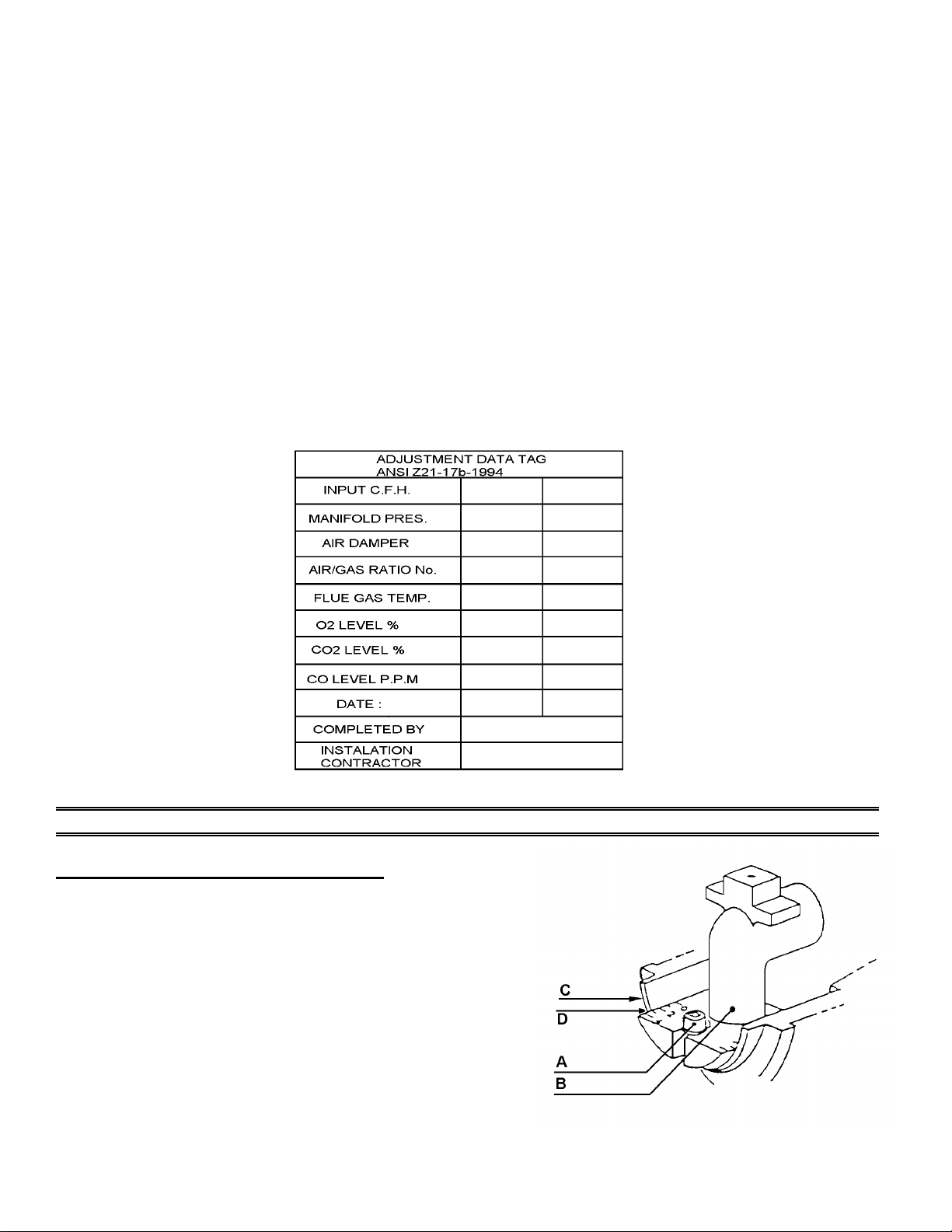
4) Remove the red protective cover by removing the three screws. Make your adjustment of stop gate, (refer
to firing rate specifications and settings charts for details). Replace and secure the air cover plate.
5) Electrical hookup: 120Volt 60 Hz incoming power lines should be connected to Terminals 1 and 2 on
burner terminal block. A manual disconnect switch must be installed in the incoming power lines.
Incoming power lines must be rigid conduit or flexible approved cable.
CAUTION: The hot wire must be connected to the black lead of the relay: neutral to the white lead. Do
not reverse the polarity. The burner will not operate with the Phase/Neutral reversed, and the control box may
be damaged. Proper earth ground should be connected to the terminal block mounting plate which should be
a solid green wire to Earth Ground.
6) Start and check the burner functions as follows:
a) Make a final check on the gas and electrical connections.
b) Check that all adjustments have been completed
c) Loosen the screw in the manifold gas test point and install a manometer.
d) Switch on power.
e) Set the thermostat at its highest setting and press the burner reset button. Allow the burner to run
through a complete cycle to check control functions.
f) Turn on the manual gas valve and reset the safety. At this stage, the burner will open the air shutter
and once it is open, the burner will prepurge for aprox.30 seconds. Allow about 66 seconds for the
control module to check all the operating circuits.
It may be necessary to repeat the starting cycle several times to free the gas train of entrapped air. If the
burner goes to lockout, reset the safety button.
7) With the burner running and flame established, check the manifold gas pressure. Adjust manifold
pressure to the correct value for the selected firing rate specified in the FIRING RATE
SPECIFICATIONS AND SETTINGS chart. After completing the setting, remove the manometer and
tighten the screws.
NOTE: Do not assume the burner is operating at optimum performance.
A COMBUSTION TEST MUST BE PERFORMED