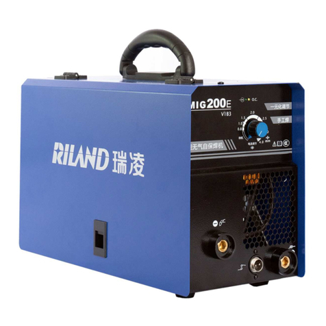
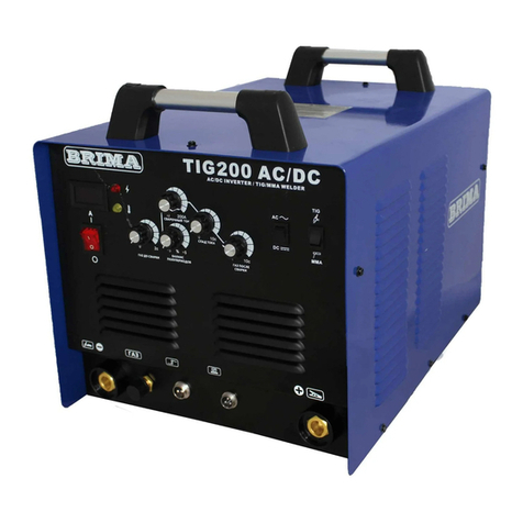
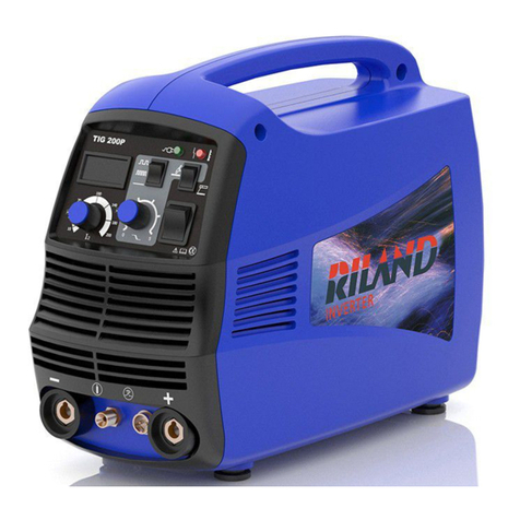
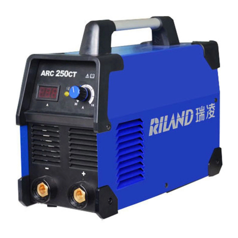
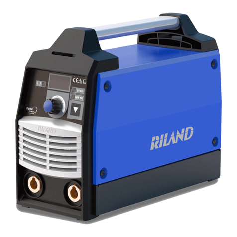
Riland ARC 200GE User manual

ARC 200GE
WELDING MACHINE
USERMANUAL


Welcome to use our company’s welding machine!
For your own and other people’s safety, please read the manual carefully before
operating. And the user manual must always be available near the welding machine.
Announcement
The contents of this manual are updated irregularity for updating of product. The
manual is only used as operation guide, except for other promises. No warranties of
any kind, either express or implied are made in relation to the description, information
or suggestion or any other contents of the manual.
Version
Version YF-TAE-0127,A1. Released on August 27, 2020.
The images shown here are indicative only. If there is inconsistency between
the image and the actual product, the actual product shall govern.

Content
1 Safety warning.......................................................................................................................................3
2 Product ...................................................................................................................................................7
2.1 General........................................................................................................................................7
2.2 Technical data............................................................................................................................9
3 Installation............................................................................................................................................10
4 Operation..............................................................................................................................................13
4.1 Front panel layout....................................................................................................................13
4.2 Operation instruction............................................................................................................... 13
4.3 Welding environment and safety...........................................................................................14
4.4 Welding problems and resolution.......................................................................................... 14
5 Daily maintenance and checking......................................................................................................16
6 Trouble shooting and fault finding....................................................................................................17
Appendix Ⅰ Welding parameter list...................................................................................................18
Appendix Ⅱ Circuit diagram................................................................................................................19

3
1 Safety warning
Security Definitions
It indicates that neglecting safety warnings may result in serious
accidents, even death or serious injury.
It indicates that neglecting safety warnings may result in minor
injury to personnel or property damage.
It indicates that neglecting safety warnings may result in
equipment failure or damage.
Personal Protection Precautions
◆Personnel with professional qualifications or relevant knowledge and skills are requested to
install, operate, maintain and repair the power source.
◆Installation, inspection and repair of power source must be carried out by electricians, and
temporary construction points should be connected by electricians.
◆Supervisors shall be provided for working in high altitude or narrow places, such as boxes,
boilers, cabins, etc.
◆Personal protective equipment, such as protective masks, overalls, insulating gloves and
insulating shoes, should be worn when working.
◆Those who use cardiac pacemakers shall not approach the power source in use and welding
workplaces without the permission of a physician.

4
Installation Operation Precautions
◆Before welding, the yellow-green grounding wire in the power line must be grounded and the
insulation of the welding cable must be ensured.
◆During welding operation, do not touch live parts such as workbench, welding parts, earth
clamp, electrode holder or welding torches.
◆Rubber insulation pads should also be laid on the ground near the operating table for welding
operations with high no-load voltage and in wet working places.
◆In the welding process, do not open the machine house and side cover.
◆Do not touch the electrically charged parts.
◆Do not use cables with insufficient cross-section, damaged insulation sheaths or exposed
conductors.
◆Maintenance operation should be carried out after 5 minutes of disconnection of the power
supply until the power indicator is completely turned off, otherwise there is a risk of electric
shock.
◆Turn off all input power when transferring work place, replacing fuse, repairing or not using
the equipment.
◆When welding steel plates with coatings or coatings, harmful fumes and gases will be
produced. Full ventilation or exhaust facilities should be used to keep fumes and toxic gases
away from the breathing area. If necessary, wear breathing protection tools.
◆When working in narrow places, such as boxes, boilers, cabins, etc., please accept the
inspection of supervisors. In order to prevent hypoxia, we should fully ventilate and wear
respiratory protective equipment.
The
power
source
shall
not
be
used
for
pipeline
thawing,
battery
load
or
motor
start-up.
Beware
of
Electric
Shocks
Beware
of
welding
fume
and
harmful
gases

5
◆Keep ventilation system of welding machine unblocked. The minimum distance between
power source and surrounding place should be greater than 0.5m. Do not cover the inlet and
outlet of equipment to ensure smooth circulation of cooling air.
◆Corresponding protective measures should be takenin the welding area to avoid fire caused
by welding mars.
◆Do not carry out welding operations in degreasing, cleaning and spraying areas.
◆Do not weld gas-filled pipes, sealing grooves (boxes) and other devices, otherwise
explosions or fires are likely to occur.
◆Do not weld near flammable gases or devices with flammable substances, otherwise
explosion or fire may occur.
◆When not welded, make sure that any component in the wire circuit does not contact the
workpiece or the earth, otherwise it may cause overheating and fire.
◆When the welding operation is stopped, remove the electrode in the welding pliers or cut off
the welding wire in the nozzle of the welding torch.
◆Those who use cardiac pacemakers shall notapproach the power source in use and welding
workplaces without the permission of a physician.
◆It is strictly forbidden to place or wrap welded cables around the body.
◆Do not place the bodybetween the welding wire and the workpiece cable. If the welding wire
cable is on the right side of the body, the workpiece cable should also be on the right side of
the body.
◆When welding or supervising welding, please wear protective appliances with adequate
shading.
Welding
Sparks
May
Cause
Fire
or
Explosion
Electrical
Base
Field
May
be
Dangerous
Arc
Rays
May
Cause
Burns

6
◆Protective barriers are set around the welding site to prevent arc or welding spatter from
injuring others.
◆Users should ensure that the welding power supply and other equipment in the environment
do not produce electromagnetic interference, otherwise corresponding shielding and
protection measures should be taken.
◆According to the manufacturer's suggestion, the power source should be connected to the
main power supply line.
◆The length of welded cables should be shortened as far as possible to make them close to
each other and to the ground.
◆Safety of all metal assemblies assembled by welding and the assemblies connected with
them should be confirmed.
◆The yellow-green grounding wire in the power line must be grounded, and the workpiece
must be well connected with the ground clamp.
◆Users should be responsible for the interference caused by welding.
◆In order to avoid the harm of noise to you and others, please wear the prescribed protective
equipment.
◆The power source with strap or handle is prohibited from using strap or handle for lifting.
◆When lifting power source with lifting forklift truck, in order to prevent dumping, please fork-
fit and fix it from side.
◆When lifting power source with crane, the cable should be tied to the suspension ring, and
the angle between the cable and the vertical direction should not exceed 15 degrees.
Avoiding
Electromagnetic
Interference
Noise
Produced
during
Welding
can
Easily
Cause
Hearing
Loss
Cautions
for
Hoisting

7
◆When the power source with cylinder and wire feeder is hoisted, the two equipments should
be unloaded from the power supply first.When moving the power source on the ground, it is
necessary to fix the cylinder with a strap or chain to prevent dumping and injuring people.
◆If the wire feeder is hoisted by lifting lugs for welding, it is necessary to ensure that it is firm
and insulated.
2 Product
2.1 General
Themachinewith MMAfunction,is digitalfunctionweldingmachinethatapplythe most advanced
inversion technology in the world.
The principle of inversion is to transform the power frequency of 50Hz/60Hz into direct current
and invert it into high frequency (33KHz) through high-power device IGBT, then perform voltage-
drop and commutation with the output high-power D.C power supply via full digital Pulse Width
Modulation (PWM) control technology. Since the switch power inversion technology is adopted,
the weight and volume decrease greatly while the conversion efficiency increase for more than
30%.
Our welding power source can offer stronger, more concentrated and more stable arc. When the
welding rod and work piece get short circuit, its response will be quicker. It means that it is easy
to design welding machine with different dynamic characteristics, and it can even adjust the
characteristics to make arc softer or harder.
The characteristic of the machine is slope. The welding current, push current and heat arc
initiation current use the same knob for synergic adjustment. And with good arc initiation and
stable power output, the welding gap and quality can reach the best effect.
The machine, with small volume, light weight and stable characteristic, can weld stainless steel,
carbon steel, copper and other color metal. Its transfer efficiency is above 85%.
Rings
Handle

8
Thanks for purchasing our products and looking forward to your precious advice, we will try our
best to perfect our products and service.
The machine is mainly used in industrial fields. It will cause radio interference if used
indoors. Please take through precaution measures.

9
2.2 Technical data
“-”: It indicates that the machine has no content or no this function.

10
The following procedures shall be operated by electrician!
Connect proper power cable to the distribution box with corresponding capacity according to the
input voltage and current (See technical parameter table). Do not connect to the inappropriate
voltage and make sure that the difference of power supply is within permitted range.
3 Installation
The welding equipment is equipped with power voltage compensation device. It keeps the
machine work normally when power voltage fluctuating ±15% of rated voltage.
When using long cable, in order to reduce voltage drop, big section cable is suggested. If the
cable is too long, it will affectthe performance of arcing and other system function, it is suggested
to use the recommend length.
⚫Make sure the intake of the machine is not covered or blocked to avoid the malfunction of
the cooling system.
⚫Make sure the earth end of power interface has been reliably and independently grounded.
Installation Procedures
a) Connect the quick plug of the electrode holder into the socket “-” of the machine, and fasten
it clockwise tightly.
b) Connect the quick plug of the earth clamp into the socket “+” of the machine, and fasten it
clockwise, the other end clamps the workpiece.
Please pay attention to the connecting terminal, DC welding machine has two connecting
ways: positive connection and negative connection.
Positive connection: work piece connects with the “+” terminal, while electrode holder
connects with “-” terminal.
Negative connection: work piece connects with the “-” terminal, while electrode holder
connects with “+” terminal.
Choose suitable way according to the working situation. If unsuitable choice is made, it will
cause unstable arc, more spatters and conglutination. If such problems occur, please
change the polarity of the fastened plug. It should adopt negative connection when welding
with alkaline electrode, while positive connection when welding with acid electrode.

11
Installation diagram
Plastic with round corner:
Iron shell
The Belt Fixing Steps (optional)
The images shown here are indicative only. If there is inconsistencybetween the image and the actual
product, the actual product shall govern.
Power
Supply
Earth
clamp
Electrode
holder
Workpiece
Power
Supply
Electrode
holder
Workpiece
Earth
clamp

12
Take the following parts to fix the belt into the
machine.
Fix the belt as figure 1 to 3. The length of the belt
can be adjusted as needed.
Figure. 1
Figure. 2
Figure. 3

13
4 Operation
4.1 Front panel layout
With stand-by button Without stand-by button
Instruction
No.
Description
1
Power indicator
2
Over heat indicator
In case of over heat, the indicator lights on
3
Stand-by button
Press the stand-by button, the power indicator lights on. The machine
enters working state.
Note:For machines without the stand-by button, turn on the power
switch on the rear panel, the power indicator lights on. The machine
enters working state.
4
Current adjustment knob
Adjust the range of output current
4.2 Operation instruction
1. Press the stand-by button, the power indicator lights on, and the fan starts running. Note:
The power switch should be turned on before pressing the stand-by button, if three is a
power switch on the rear panel of the machine.
For machines without the stand-by button, turn on the power switch on the rear panel, the
power indicator lights on, and the fan starts running.
2. Set the welding current according to the welding requirement.
3. Generally, welding current is adequate to welding electrode according with the section
“Appendix Ⅰ Welding parameter list”.
⚫ Fan dormancy function

14
The fan is in the dormancy state when the welding machine starts welding. It won’t work until
the internal temperature above 45℃. And it will stop working when the temperature is less
than 35℃.
4.3 Welding environment and safety
⚫ Working surrounding
a) Weldingshould becarriedoutin drysurroundings.Theair humiditylevelshouldnotbehigher
than 90%.
b) The temperature should be between -10 C to 40 C.
c) Don’t use the welding machines in sunshine or rain. Keep it off water.
d) Don't use the machines in the places of dust or corrosive air.
e) MIG welding should not be carried out in places with quick air flow.
⚫ Safety norms
Protection circuit of over-voltage, over-current and over-heat circuits are designed in the
welding machines. It will stop working automatically when the input voltage, output current
or internal temperature exceed the rated value. But if the machines are excessively used,
such as with input voltage higher than the rated, the machine might be damage. Please pay
close attention to the following matters.
a) Keep good ventilation!
The welding machines work with high welding current. Nature air flow can’t reach the
requirement of heat dissipation. So the fans are installed as cooling system to ensure stable
performance.
Make sure the ventilation windows are not covered or blocked. The distance between the
machines and things around should not be less than 0.3m. Good ventilation is good for
welding performance and operational life.
b) Never over load!
Check the maximum rated current (according to the Duty Cycle chosen). Make sure the
welding current is never higher than the rated value. Over current running will obviously
shorten the operation life, even damage the machine.
c) Never over voltage!
The Input Voltage could be found in Technical data diagram. The auto-compensation
function will keep the welding current in the rated range. If the input voltage exceed the
permissible value, the machine would be damaged. Users should take protective measures
in advance to avoid it.
4.4 Welding problems and resolution
The phenomenon listed below may happen due to relevant accessories used, welding material,
surroundings and power supply. Pleas improve surroundings and avoid these problems..

15
⚫ Arc starting difficulty. Arc interruption happens easily.
a) Examine whether grounding wire clamp contacts with the work pieces well.
b) Examine whether each joint has improper contact.
⚫The output current fails to reach rated value.
The deviation of power voltage from rated value may cause that the output current does no
accord with adjusted value.When the power voltage is lowerthan rated value, the maximum
output current may be lower than rated value.
⚫The current can not keep stable during operation. This situation may
relate to the following factors:
a) The voltage of electric power network changes;
b) Serious interference from electric power network or other electric facilities.
⚫ Gas vent in welds.
a) Examine whether the gas supply circuit has leakage.
b) Examine whether there is sundries such as oil, dirt, rust, paint etc. on the surface.

16
5 Daily maintenance and checking
⚫ Daily maintenance
a) Remove dust regularly with dry compressed air. If the welding machine is used in
surroundings with heavy smoke and polluted air, it is necessary to remove dust at least one
time one month.
b) The pressure of compressed air shall fall to required level to prevent damage to small
components in the machine.
c) Examine inside electric joints and ensure perfect contact (Especially plugs and sockets).
Fasten the loosing joints. In case of oxidation, remove oxide film with sand paper and
connect again.
d) Prevent water from entering into the machine and prevent the machine from getting moist. If
any, blow and dry. Measure the insulation with megohmmeter to make sure it is qualified to
use.
e) If the welding machine is not used for a long time, pack the machine in original package and
store in dry surroundings.
f) Every time the wire feeder operates for 300hours, grind the electrical carbon brush and clear
up the armature commutator. Rinse speed reducer,apply 2# Molybdenum Disulfide lubricant
to the turbine, whirlpool rod and bearing.
All the maintenance and testing must be carried out when the power supply is totally cut
off. Please make sure the power is off before opening the closure.
⚫ Daily checking
WELDING POWER
Position
Checking keys
Remarks
Operation
control board
➢
➢
Operation, conversion and
installation of the switch
Check the state of the power
indicator light
Lead to unstable
arc sending
and wire
Cool-down fan
➢
Check if the fan state and the sound
is normal of not
Clean the residue and
reason and solve it
check the

17
Power part
➢
➢
➢
Check if there is abnormal liberation
and sound when the
power is on
Check if there is smell when the
power is on
Whether the outside color change
or get warm
-
Outer parts
➢
➢
Whether the wire feeder pipe is
broken,and the connector is loosen
Whether the outer shell or other
connect parts are loosen
-
CABLE
Position
Checking keys
Remarks
Output cable
➢
➢
Wearing-out of the cable insulated
material
Cable connecting head naked
(insulation damage), or loosen (the
end of power supply, and cable of
main material connecting point)
For life securityand stable welding,
adopt suitable method to check
according to working place
➢Simple check daily
➢Careful and in-depth check on
fixed period
Input cable
➢
➢
If the connection between the plug
and the power socket is firm If the
power input end cable fixed
➢
If the input cable is worn out and
bares the conductor
Earth cable
➢
If the earth cable that connects the
main part is broken and
connects tightly
In case of leakage and to ensure
safety, please do perform daily
checking
6 Trouble shooting and fault finding
Notes: The following operations must be performed by qualified electricians with valid
certifications. Before maintenance, you are suggested to contact local distributor to
verify qualification.

18
Malfunctions
Solution
Fan does not rotate;
No welding output
➢
➢
➢
Confirm the power switch is on.
Power supply available for input cable.
Check if the silicon bridge is damaged.
➢
There is malfunction occurs in the supplementary power
source on control board (contact dealers).
Fan works normally;
No welding output
➢
➢
➢
Check if all the sockets in the machine are connected well.
There is open circuit or badness of connect at the joint of
output terminal.
The control cable on the torch is broken off or the switch is
damaged.
➢
The control circuit is damaged.(contact to dealers)
Fan works normally;
Abnormal indicator lights.
➢
➢
It might be over-current protection, please turn off the power
switch; restart the machine after the abnormal indicator light
winked.
It might be overheating protection, please wait for about 2-3
minutes until the machine renew without turn off the power
switch.
➢
It might be multifunction of inverter circuit. (contact dealers)
Appendix Ⅰ Welding parameter list
Please refer to the following parameter in operation.
⚫ Generally, welding current is adequate to welding electrode according with as
following.
Electrode
specification
Φ1.6
Φ2.0
Φ2.5
Φ3.2
Φ4.0
welding
current
25-40A
40-65A
50-90A
90-130A
140-210A
Table of contents
Other Riland Welding System manuals

Riland
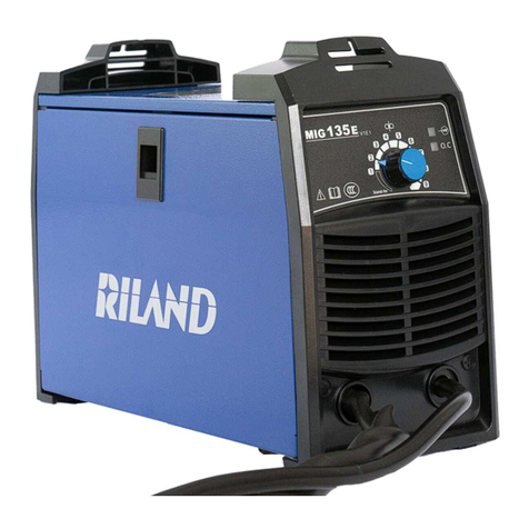
Riland MIG 135E User manual

Riland
Riland ARC 250GE User manual

Riland
Riland ARC 250CT User manual

Riland
Riland TIG 315PAC/DC User manual

Riland
Riland Super160 User manual

Riland
Riland TIG 200CT User manual

Riland
Riland TIG 200P User manual

Riland
Riland TIG 200 AC/DC User manual

Riland
Riland MIG 200E User manual

Riland
Riland Multipro 200SP User manual
Popular Welding System manuals by other brands

Lincoln Electric
Lincoln Electric COMMANDER SVM153-A Service manual

Harger
Harger Ultraweld UltraShot US500 instructions

Miller Electric
Miller Electric Subarc DC 650 Specification sheet

Leister
Leister VARIMAT S operating instructions

Parkside
Parkside PESG 120 A1 Operation and safety notes

GEORGE FISCHER
GEORGE FISCHER SG 160 instruction manual