RITE-HITE SlideAir User manual

Manual Part #: 39500143
Model: SLDAIR
Publication: AMEN00119 2020-07-06
SlideAir™
Pneumatic Safety Curtain
Installation/Service/Owner's Manual
Language: English (Hazards: English, French)
NOTICE TO USER . . . . . . . . . . . . . . . . . . . . . . 2
SAFETY. . . . . . . . . . . . . . . . . . . . . . . . . . . . . . . 3
INSTALLATION
Preparation. . . . . . . . . . . . . . . . . . . . . . . . . . . . . 5
Single Pedestal Mount . . . . . . . . . . . . . . . . . . . . 7
Single Swivel Mount . . . . . . . . . . . . . . . . . . . . . . 7
With Vertical Supports . . . . . . . . . . . . . . . . . . . . 8
Without Vertical Supports . . . . . . . . . . . . . . . . . . 8
Extended Curtain Nose (Optional) . . . . . . . . . . . 8
Air Supply Regulator (Optional) . . . . . . . . . . . . . 8
Electrical. . . . . . . . . . . . . . . . . . . . . . . . . . . . . . . 9
Final Checklist . . . . . . . . . . . . . . . . . . . . . . . . . 11
ELECTRICAL
SlideAir Control Box Wiring Diagram . . . . . . . . 12
Junction Box Wiring Diagram – 110 VAC . . . . . 13
Junction Box Wiring Diagram – 24 VDC. . . . . . 14
Proximity Switch Wiring Diagram . . . . . . . . . . . 15
Control Box Layout – 110 VAC . . . . . . . . . . . . . 16
Junction Box Layout . . . . . . . . . . . . . . . . . . . . . 17
MAINTENANCE
Planned Maintenance. . . . . . . . . . . . . . . . . . . . 18
Troubleshooting . . . . . . . . . . . . . . . . . . . . . . . . 18
PARTS . . . . . . . . . . . . . . . . . . . . . . . . . . . . . . . 19
ABBREVIATIONS . . . . . . . . . . . . . . . . . . . . . 20
WARRANTY . . . . . . . . . . . . . . . . . . . . . . . . . . 24

SlideAir™ Pneumatic Safety Curtain Installation/Service/Owner's Manual Rite‑Hite®
2 Publication: AMEN00119 2020-07-06
NOTICE TO USER
Thank you for purchasing a Rite‑Hite product.
The SlideAir pneumatic sliding curtain provides safety
and reduces process driven hazards in manufacturing
applications.
Read and understand manual before beginning the
installation, operation or servicing of this product.
Before work begins, verify space clearance requirements
from architectural drawings.
Complete "Final Checklist" (page 11) before leaving site.
Store manual near the unit.
The English version of this manual shall prevail over any
error in, or conicting interpretation of, any translations.
Rite‑Hite reserves the right to substitute and/or modify
parts and drawings (electrical and architectural) from
those contained in this manual. Separate prints may be
included with the unit.
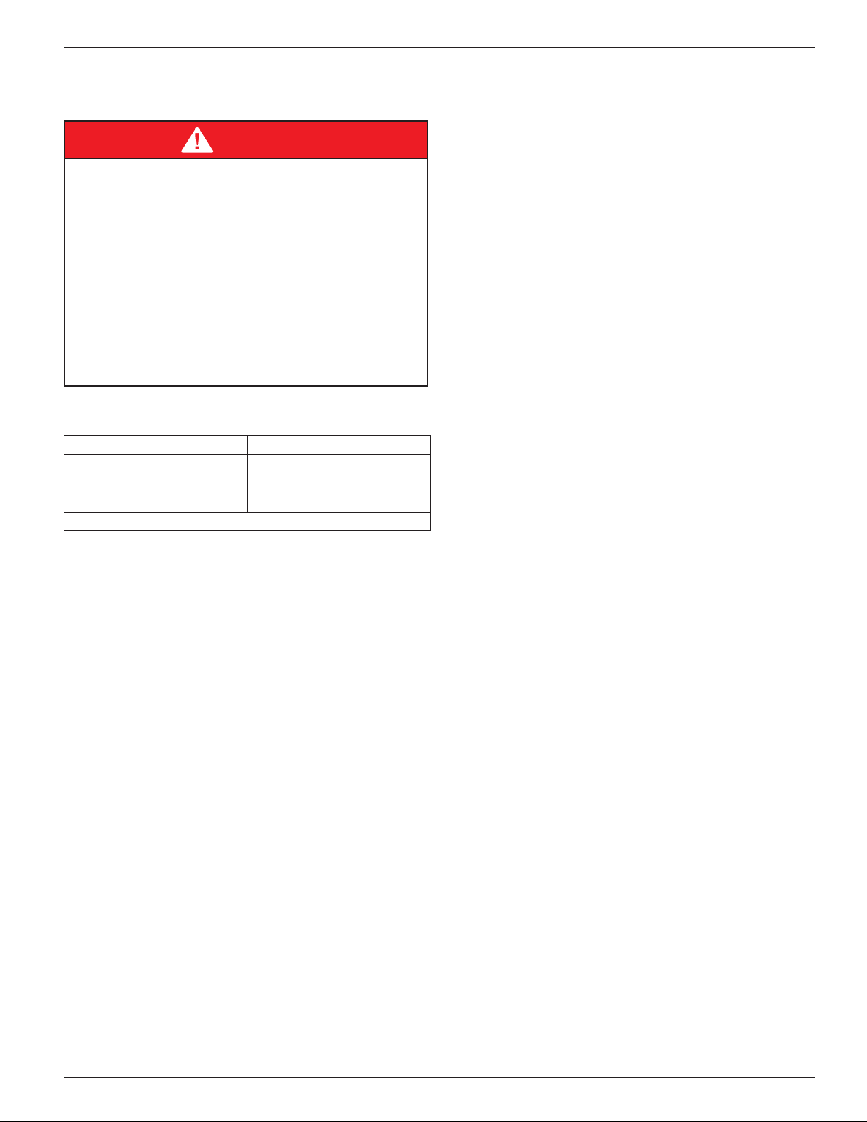
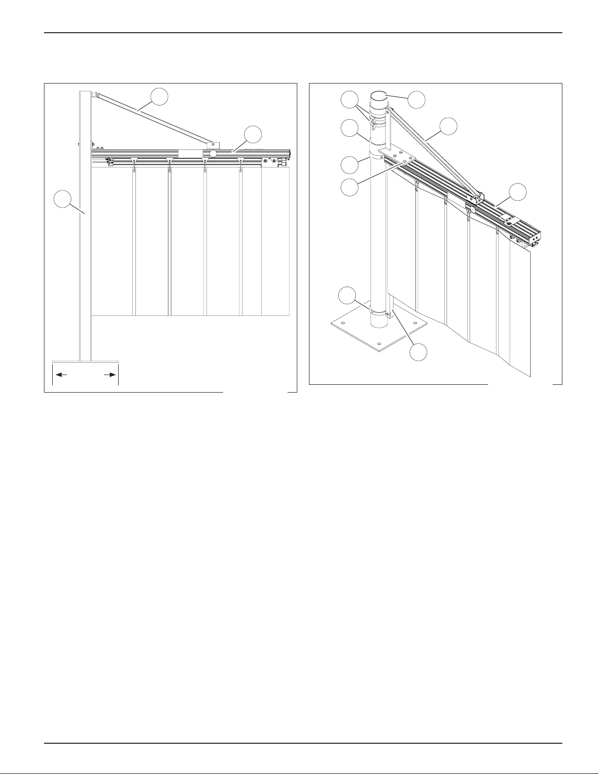
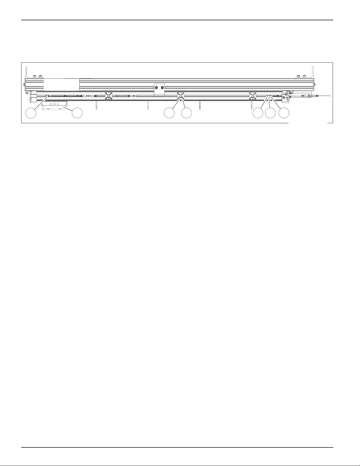
When ordering parts, include your unit serial or RHC
number located on the label located on the top of the main
header extrusion (Figure 3 on page 8).
For best results, have this product serviced by an
authorized Rite‑Hite representative.
A Planned Maintenance Program (P.M.P.), customized to
your specic operation is available and recommended.
For a P.M.P., contact your local Rite‑Hite representative
or Rite‑Hite technical support at (U.S.) 1‑563‑589‑2722,
1‑888‑456‑3625, (S.A.) +55 21 99616 4421,
(E.U.) +49‑5693 98700.
NOTICE
Store dry between 40° and 80° F, (4° and 27° C).
The Rite‑Hite®products in this manual are covered by one or more
of the following U.S. patents: 6192960, 6212826, 6330763, 6360487,
6481487, 6560927, 6598648, 6615898, 6688374, 6837296, 6901703,
6964289, 7034682, 7045764, 7111661, 7114753, 7151450, 7578097,
7699089, 7748431, 7757437, 8037921, 8167020, 8113265, 8863815,
8857498, 9222304, 9388634, 9309717, 9493984, 9556672, 9631427,
9771754 and may be covered by additional pending U.S. and foreign
patent applications.
Rite‑Hite®, SlideAir™ are trademarks of Rite‑Hite.
Manufactured by Rite‑Hite Doors, Inc.

Rite‑Hite®Installation/Service/Owner's Manual SlideAir™ Pneumatic Safety Curtain
Publication: AMEN00119 2020-07-06 3
SAFETY
Safety Identifications
DANGER
Indicates a hazardous situation which, if not
avoided, will result in death or serious injury.
Indique une situation dangereuse qui, si elle n’est
pas évitée, peut entraîner la mort ou de graves
blessures.
WARNING/AVERTISSEMENT
Indicates a hazardous situation which, if not
avoided, could result in death or serious injury.
Indique une situation dangereuse qui, si elle n’est
pas évitée, peut entraîner la mort ou des
blessures graves.
CAUTION/ATTENTION
Indicates a hazardous situation which, if not
avoided, could result in minor or moderate injury.
Indique une situation dangereuse qui, si elle n’est
pas évitée, peut entraîner des blessures légères à
modérées.
NOTICE
Indicates a situation which can cause damage to the
equipment, personal property and/or the environment,
or cause the equipment to operate improperly.
NOTE:A note is used to inform you of important
installation, operation, or maintenance information.
Lockout Procedure
Barricade work area and post safety warnings.
Power supply and control must:
• Be disconnected or locked in OFF position
using a lockout device approved by local
codes.
• Have signage that;
−Clearly states repairs are being made.
− Identies person responsible for lockout condition.
NOTE:Only this person should be able to remove
warnings and lockout device.
−Withstands environmental conditions (weather,
wet, and damp, etc.) and remains readable.
190820

SlideAir™ Pneumatic Safety Curtain Installation/Service/Owner's Manual Rite‑Hite®
4 Publication: AMEN00119 2020-07-06
SAFETY
General
DANGER
A qualied electrician should install the wiring in
accordance with local electrical codes.
Use lockout procedures to prevent death or severe
personal injury.
L'installation du câblage doit être eectuée par un
électricien qualié, conformément aux normes
électriques nationales et locales.
An de réduire le risque de blessures graves ou
mortelles, utilisez des procédures de verrouillage.
DANGER
To reduce risk of injury or death, an earth ground
connection must be made to the green/yellow
control box ground terminal.
If metal conduit is used as the ground connector,
a ground bushing and green/yellow wire must be
properly attached to the conduit for connection to
the ground terminal, per local electrical codes.
Pour réduire le risque de blessures ou de décès,
un raccordement de terre doit être fait à la boite
de contrôle verte/jaune de la borne de terre.
Si le connecteur de terre utilisé est un conduit
métallique, un manchon de mise à la terre et un
câble vert/jaune doivent être correctement xés
au conduit un raccordement à la borne de terre,
par codes électriques locales.
WARNING/AVERTISSEMENT
Input air pressures above maximum allowable
pressure can result in damage to product or injury
to personnel.
Des pressions d'air d'entrée supérieures à la
pression maximale autorisée peuvent
endommager le produit ou blesser le personnel.
WARNING/AVERTISSEMENT
Cancer and Reproductive Harm
www.P65Warnings.ca.gov
Canver al problèmes du système de reprodution
www.P65Warnings.ca.gov
CAUTION/ATTENTION
Barricade the work area during installation or
maintenance.
Barricader la zone de travail pendant l'installation
ou l'entretien.
NOTICE
The safest location for conduit is at the bottom of the
control box. Failure to install conduit at the bottom of
the control box may void the warranty.
Be extremely careful when drilling conduit holes into
the control box. Drilling too deeply or allowing debris
to fall into electrical components may cause severe
equipment damage or component failure.
DO NOT turn control box upside down when drilling
holes. Holes on top of control box may allow dust
and moisture to enter the control box.

Rite‑Hite®Installation/Service/Owner's Manual SlideAir™ Pneumatic Safety Curtain
Publication: AMEN00119 2020-07-06 5
INSTALLATION
Preparation
DANGER
Per local electrical codes, when working with
electrical or electronic controls:
• Power source must be locked out and marked
• A qualied electrician should install the wiring
Selon les codes électriques locaux, lorsque vous
utilisez des commandes électriques ou
électroniques:
• La source d'alimentation doit être verrouillée et
marquée
• Un électricien qualié doit installer le câblage
Required Tools
Level Drill
Hammer Hammer drill
Combination wrenches Wire strippers
Screwdriver Cargo straps (for lifting)
Anchors
NOTE:Verify the following information before starting with
the installation.
Site Evaluation
The SlideAir can be installed either as a free standing unit
or mounted to a machine structure in a machining, welding
or other type of environment.
1. Check for electrical prints included in the parts or
control box. They supersede any prints in this manual.
2. Alternate measurements in parentheses are in metric.
3. Make sure you are working at the correct location and
have any required work permits.
4. Inspect installation site to make sure area is free
of overhead obstructions (sprinkler pipes, HVAC
systems, electrical supply lines, etc.) that might
interfere with the lifting of the header assembly
during installation.
5. Detour material handling equipment (fork lift trucks,
etc.) during the installation of the unit.
6. Make sure that the electrician is ready to bring the
correct electrical power supply to the control box.
7. Make sure the electrical power can be shut off without
interfering with other plant operations.
8. Check which mounting method will be used for the
SlideAir assembly.
9. Make sure nothing is buried in the floor, if using
anchors.
10. Make sure there is an air supply connection run to the
installation site.
11. Inspect installation site to make sure the area allows
adequate clearance for robotic machining, welding or
other types of operation.
12. Move the entire crate of components as close to the
working area as possible.
13. If multiple units are being installed, the control
box must be installed with the matching unit. The
serial number for your unit is on the label located on
the top of the main header extrusion (Figure 4 on
page 8).
14. To verify proper installation, use "Final Checklist" on
page 11.

SlideAir™ Pneumatic Safety Curtain Installation/Service/Owner's Manual Rite‑Hite®
6 Publication: AMEN00119 2020-07-06
INSTALLATION
Preparation Continued
Parts Inventory
1. Remove all assemblies and parts from the shipping
container.
2. Arrange parts on the floor using the exploded view as
a guide, see "PARTS" on page 19.
3. Check to insure all parts are included. Call technical
support if you have any questions.
Header Assembly
The header assembly includes the aluminum extrusion
structure, rodless cylinder, curtain trolleys, proximity
switch(es) (optional), and air hose. The cylinder pulls
the curtain open or closed across the opening when
air is supplied.
Curtain
The standard curtain is made of either opaque or
translucent material. Standard 8 in (203 mm) pleats allow
the curtain to fold back to a compact prole when
not needed.
Vertical Supports (Optional)
The vertical supports are rugged 3 in (76 mm) square
tubing. Brackets allow easy assembly of the cylinder
assembly to the vertical supports.
Dual vertical supports will be mounted on 8 in (203 mm)
square plates.
A single pedestal support (A) "Figure 1" on page 7
will be mounted on 16 in (406 mm) square plates to
compensate for the hanging load.
Junction Box Assembly (Optional)
The Junction box assembly includes a four way air
control valve, and the necessary terminal blocks to easily
incorporate an output signal from the existing machine
controller. The four way valve is available as 24 VDC or
110 VAC.
Control Box Assembly (Optional)
The control box assembly includes a four way air control
valve, open, close and stop push buttons, and (2) 24 VDC
relays. This control box allows the SlideAir to be opened
or closed by momentarily pushing a button, or from a
24 VDC output signal from a machine controller. This box
requires use of a 110 VAC air valve.

Rite‑Hite®Installation/Service/Owner's Manual SlideAir™ Pneumatic Safety Curtain
Publication: AMEN00119 2020-07-06 7
INSTALLATION
Single Pedestal Mount
A
16 in
(406 mm)
B
C
1. The installation for the dual support posts can be
used for the single pedestal mount.
2. Attach the support arm (B) to the pedestal (A) and
the header (C) for support.
Single Swivel Mount
A
B
C
D
D
D
F
G
H
E
D
F
E
I
G
B
C
F
H
1. Level and mount swivel post (D) using 3/8 in (10 mm)
bolts if fastening to a machine base or 3/8 in (10 mm)
concrete anchors if securing to a concrete floor.
2. Slide one of the swivel stops (F) and the weld
ring (I) on to the tube before sliding on the head
weldment (E).
3. If utilizing the additional swivel stops, slide over the
tube after the bottom portion of the head weldment,
but before the top portion is slid on.
4. Position the head weldment to the correct height and
hold in place from the underside using the weld ring.
5. Secure the SlideAir assembly to the forks of a fork
truck with C‑clamps. Position with the curtain and air
cylinder hanging down. Check the assembly to verify
that installation will provide the desired open/close
direction.
6. Raise the assembly and position it so that holes in
the extrusion match the holes in the head weldment.
Attach head weldment to extrusion using provided
fasteners (G).
7. Install support arm (B) and curtain attachment
angle (H).
Figure 1 Figure 2

SlideAir™ Pneumatic Safety Curtain Installation/Service/Owner's Manual Rite‑Hite®
8 Publication: AMEN00119 2020-07-06
INSTALLATION
With Vertical Supports
B A
Serial
Number
Label
Figure 3
D E
D E
C
A
1. Secure the SlideAir assembly to the forks of a fork
truck with C‑clamps. Position with the curtain and air
cylinder hanging down. Check the assembly to verify
that installation will provide the desired open/close
direction.
2. Raise the assembly and position it so the support
brackets align with the holes drilled in the top of the
vertical support posts.
3. Insert (2) 5/16 in x 4 in (8 mm x 102 mm) bolts (B)
through the vertical support posts (A) and the support
bracket. Repeat for second support posts. Tighten all
bolts securely.
4. Level the vertical support posts and fasten securely.
Use 3/8 in (10 mm) bolts if fastening to a machine
base or 3/8 in (10 mm) concrete anchors (C) if
securing to a concrete floor. Use 8 in (203 mm)
square plates for dual support (D) or 16 in (406 mm)
for single support (E).
5. Remove clamps securing SlideAir assembly to the
fork truck.
Without Vertical Supports
1. Secure the SlideAir cylinder assembly to the forks of
a fork truck with C‑clamps. Position with the curtain
and air cylinder hanging down. Check the assembly
to verify that installation will provide the desired open/
close direction.
2. Raise the assembly and position it so the assembly is
in close proximity to where it will be hung.
3. Support the SlideAir assembly to the machine with a
minimum of (4) 5/16 in (8 mm) bolts. Drill holes in the
aluminum extrusion as necessary, but DO NOT drill
through an area that will effect the travel of the curtain
or the trolleys.
4. Remove clamps securing SlideAir assembly to the
fork truck.
Extended Curtain Nose (Optional)
If the unit is congured with an optional 2 in (51 mm) or
8 in (203 mm) extended nose:
1. Install the stiffener plate (supplied) with the notch
pointed downward.
2. Slide stiffener plate into the pocket in the curtain
where it attaches to the cylinder trolley block and affix
using 1/4 in ‑ 20 machine screws.
3. Optional: Use the spacer block (supplied) to change
the distance between the stiffener plate and the
cylinder trolley block.
Air Supply Regulator (Optional)
1. Route the main air line through the optional pressure
regulator. The cylinder rated operational pressure
range is from 29 psi – 116 psi (200 kPa – 800 kPa).
For best results, maintain an operating pressure
between 60 psi – 90 psi (414 kPa – 621 kPa).
2. Connect an air line from the outlet of the pressure
regulator to the inlet of the four way control valve
on the junction box or control box, "Figure 5" on
page 9.
3. Using the quick connections connect both air
lines from each end of the cylinder to outlet ports
A and B on the four way control valve, "Figure 5"
on page 9.
Figure 3
Figure 4

Rite‑Hite®Installation/Service/Owner's Manual SlideAir™ Pneumatic Safety Curtain
Publication: AMEN00119 2020-07-06 9
INSTALLATION
Electrical
Control Box (Optional)
C
A B
A. Cylinder Port A
B. Cylinder Port B
C. Air Supply Inlet (Back Side)
1. Install control box and remote disconnect
approximately 54 in (1372 mm) above floor level.
2. Provide 110 VAC power to the control box. Wire
per the wiring diagram, see "SlideAir Control Box
Wiring Diagram" on page 12.
3. Connect optional proximity switch wires to the
terminal blocks per the wiring diagram provided,
see "SlideAir Control Box Wiring Diagram" on
page 12.
Power/Startup
1. Turn power on to the control box.
2. Turn on air supply.
3. Press the open button; the curtain will slide to the
storage position.
Junction Box (Optional)
1. Install junction box and suggested remote disconnect
(supplied by others) in an area that can be accessed
for maintenance.
2. Bring signal wires from the machine controller to the
terminal blocks provided. The signal wires type will
need to match the type of valve (supplied) (110 VAC
or 24 VDC). Connect the optional proximity switch
wires to the appropriate terminal blocks. Wire per
instructions provided, see "Junction Box Wiring
Diagram – 110 VAC" on page 13 or "Junction
Box Wiring Diagram – 24 VDC" on page 14.
Figure 5

SlideAir™ Pneumatic Safety Curtain Installation/Service/Owner's Manual Rite‑Hite®
10 Publication: AMEN00119 2020-07-06
INSTALLATION
Electrical Continued
Proximity Switch Adjustment
A
B
C
D
E
16
G
18
J
K
2
17
25
27
L
M
N
B
A
C
D
E
F
B D C F A EG
1. Optional storage (A) and extended (B) proximity
switches are installed in the groove located on the air
cylinder and feature an M8x1‑3PIN plug.
2. Route and secure the optional proximity switch cables
using the adhesive cable tie mounts (C) and cable
ties (D) along the cylinder.
3. The proximity switches are pre‑aligned from the
factory, but if adjustment is needed, loosen the
locking screw (E) and slide in the groove to adjust.
4. The indicator light (F) will illuminate when the cylinder
trolley (G) is in proximity of the switch.
5. See "Proximity Switch Wiring Diagram" on page
15 for required electrical connections.
Figure 6

Rite‑Hite®Installation/Service/Owner's Manual SlideAir™ Pneumatic Safety Curtain
Publication: AMEN00119 2020-07-06 11
INSTALLATION
Final Checklist
#DESCRIPTION N/A
1. Control box conduit is mounted on the bottom.
2. Ground wires properly terminated to ground terminal.
3. Shield wires properly terminated to ground terminal.
4. Proper mounting fasteners used.
5. All fasteners are tightened and secure.
6. Input pressure is within desired range.
7. Curtain tabs slide freely in extrusion track.
8. Optional proximity switches are installed and adjusted.
9. Curtain does not drag across oor while in operation.
10. Verify function of Open, Stop, and Close buttons if equipped with control box.
11. Verify operation.
12. Area clean of debris from installation.
2020‑05‑08

SlideAir™ Pneumatic Safety Curtain Installation/Service/Owner's Manual Rite‑Hite®
12 Publication: AMEN00119 2020-07-06
ELECTRICAL
SlideAir Control Box Wiring Diagram
CONTROL BOX FUSING
DEVICE VOLTAGE CURRENT RATING
5
MC1
35
5
= TERMINAL BLOCK
= COMPONENT NAME
= ASSIGNED WIRE NUMBER
= LOCAL TERMINATION NUMBER
ELECTRICAL KEY:
ALL BLACK WIRES ARE AT POTENTIALLY
LETHAL VOLTAGES.
CAUTION:
1 AMP (MDL)F1 110-120
INCOMING POWER
PE
1 110 VAC
PE
F1
STOP
2
134
CLOSE
1A
11 4
CLOSE VALVE
PORT B
NC
NO
NO
4
OPEN
3
34
CR2
11 4
SPECIFIED.
NOTE: USE 16 AWG WIRE FOR ALL COLORS.
USE BLACK WIRE UNLESS COLOR IS
4 2
3
OPEN VALVE
PORT A
3CR1 4
3
3
11
11
18
CR1
CR2
18
END USER SUPPLIED
24 VDC
OPEN COMMAND
END USER SUPPLIED
24 VDC
CLOSE COMMAND
6
N.O. STORAGE PROX.
+
5
7
N.O. EXTENDED PROX.
TO END USER
CONTROL
SYSTEM
OPTIONAL WIRING
FROM DISCONNECT
L
N
1
1
PART #
MODEL NUMBER
DOORS INC.RITE-HITE
MM-DD-YY
DO NOT SCALE DRAWING
0.04015
5
40
80
+/- 1 DEG
FINISH
ANGLES
80
15
40
-
APPROVED BY
INITIAL ECN
DATE ISSUED
REF
0.060
0.100
0.125
INCH TOLERANCES
0.125
0.25
UP TO
1.25
0.125
0.25
1.25
OVER
0
5
DRAWN BY
0.005
0.010
+ / -
0.020
0.030
DATE
DATE
SIZE
SCALE
DWG NO
DATE
TITLE
SHEET
REV
NEXT ASSEMBLY
REV DESCRIPTION
REVISION HISTORY
ECN APPROVED
DATE BY
R
CHECKED BY
MATERIAL / PART NO
DWG NO SHEET REV
R
C
A5220E002
5220E002
RITE-HITE
DOORS INC.
6"=1'
B
B
SLIDE AIR WIRING DIAGRAM
VERTIGUARD WIRING DIAGRAM
SLDAIR / VTGD
17250095
6/25/1996
2833
3/15/2000
1999
BREVISE FOR NEW PROX SWITCH 7766 6/19/2019 SHC
BLACK
BLACK
BROWN
-
BLUE 8
24VDC
0VDC
*SLIDE AIR ONLY*
<5220E002_REV B.pdf>

Rite‑Hite®Installation/Service/Owner's Manual SlideAir™ Pneumatic Safety Curtain
Publication: AMEN00119 2020-07-06 13
ELECTRICAL
Junction Box Wiring Diagram – 110 VAC
5
MC1
35
5
= TERMINAL BLOCK
= COMPONENT NAME
= ASSIGNED WIRE NUMBER
= LOCAL TERMINATION NUMBER
ELECTRICAL KEY:
OPEN VALVE
PORT A
5
N.O. STORAGE PROX.
+
4
6
N.O. EXTENDED PROX.
TO END USER
CONTROL
SYSTEM
3
2
1
CLOSE VALVE
PORT B
110 VAC OPEN SIGNAL
COMMON
110 VAC CLOSE SIGNAL
TERMINAL
STRIP
OPTIONAL
FIELD WIRING RITE-HITE WIRING
PART #
MODEL NUMBER
DOORS INC.RITE-HITE
MM-DD-YY
DO NOT SCALE DRAWING
0.040155
40
80
+/- 1 DEG
FINISH
ANGLES
80
15
40
-
APPROVED BY
INITIAL ECN
DATE ISSUED
REF
0.060
0.100
0.125
INCH TOLERANCES
0.125
0.25
UP TO
1.25
0.125
0.25
1.25
OVER
0
5
DRAWN BY
0.005
0.010
+ / -
0.020
0.030
DATE
DATE
SIZE
SCALE
DWG NO
DATE
TITLE
SHEET
REV
NEXT ASSEMBLY
REV DESCRIPTION
REVISION HISTORY
ECN APPROVED
DATE BY
R
CHECKED BY
MATERIAL / PART NO
DWG NO SHEET REV
R
C
A5220E004
5220E004
RITE-HITE
DOORS INC.
1"=1"
A
A
SLIDE AIR JUNCTION BOX
WIRING DIAGRAM (110 VAC)
SLDAIR
53530004
6/25/1996
2833
3/15/2000
2000
AREVISE FOR NEW PROX SWITCH 7766 6/19/2019 SHC
BROWN
BLUE
-
7
BLACK
BLACK
0VDC
24VDC
<5220E004_REV A.pdf>

SlideAir™ Pneumatic Safety Curtain Installation/Service/Owner's Manual Rite‑Hite®
14 Publication: AMEN00119 2020-07-06
ELECTRICAL
Junction Box Wiring Diagram – 24 VDC
5
MC1
35
5
= TERMINAL BLOCK
= COMPONENT NAME
= ASSIGNED WIRE NUMBER
= LOCAL TERMINATION NUMBER
ELECTRICAL KEY:
3
2
1
24 VDC OPEN SIGNAL
0 VDC
24 VDC CLOSE SIGNAL
TERMINAL
STRIP
OPTIONAL
FIELD WIRING
RITE-HITE WIRING
CLOSE VALVE
PORT B
OPEN VALVE
PORT A
PART #
MODEL NUMBER
DOORS INC.RITE-HITE
MM-DD-YY
DO NOT SCALE DRAWING
0.040155
40
80
+/- 1 DEG
FINISH
ANGLES
80
15
40
-
APPROVED BY
INITIAL ECN
DATE ISSUED
REF
0.060
0.100
0.125
INCH TOLERANCES
0.125
0.25
UP TO
1.25
0.125
0.25
1.25
OVER
0
5
DRAWN BY
0.005
0.010
+ / -
0.020
0.030
DATE
DATE
SIZE
SCALE
DWG NO
DATE
TITLE
SHEET
REV
NEXT ASSEMBLY
REV DESCRIPTION
REVISION HISTORY
ECN APPROVED
DATE BY
R
CHECKED BY
MATERIAL / PART NO
DWG NO SHEET REV
R
C
A5220E005
5220E005
RITE-HITE
DOORS INC.
1"=1"
A
A
SLIDE AIR JUNCTION BOX
WIRING DIAGRAM (24 VDC)
SLDAIR
53530003
6/25/1996
2833
3/15/2000
2000
AREVISE FOR NEW PROX SWITCH 7766 6/19/2019 SHC
5
N.O. STORAGE PROX.
+
4
6
N.O. EXTENDED PROX.
TO END USER
CONTROL
SYSTEM
BROWN
BLUE
-
7
BLACK
BLACK
0VDC
24VDC
<5220E005_REV A.pdf>

Rite‑Hite®Installation/Service/Owner's Manual SlideAir™ Pneumatic Safety Curtain
Publication: AMEN00119 2020-07-06 15
ELECTRICAL
Proximity Switch Wiring Diagram
BROWN
BLACK
BLUE
PNP
N/O CONTACT
+
-
RL
THIS DOCUMENT IS THE PROPERTY
OF RITE-HITE® DOORS INC. SUBJECT
MATTER HEREIN IS CONFIDENTIAL.
DO NOT USE, REPRODUCE, COPY OR
DISCLOSE EXCEPT WITH WRITTEN
CONSENT OF RITE-HITE® DOORS INC.
CONFIDENTIAL
M8x1 - 3 PIN
INDICATOR LIGHT
A
DETAIL A
PIN ALLOCATION
SCALE 6 : 1
PIN #1
PIN #4
PIN #3
NEXT ASSEMBLY
FINAL ASSEMBLY
5220M160 5220M162
REVISION HISTORY
REV.
DATE
NOTE
ECN
BY
A
6/25/2019
RELEASE
7766
SHC
PIN ALLOCATION
PIN #
WIRE COLOR
ALLOCATION
1
BROWN
+
3
BLUE
-
4
BLACK
OUTPUT
A
B
4
3
2
1
B
1
2
3
4
A
SLDAIR
MODEL
06/17/2019
DRAWN DATE
SHC
DRAWN BY
6/17/2019
DATE ISSUED
FINISH
REFERENCE
72700322
PART#
=
.050
=
.010
=
.005
=
1.0
UNLESS OTHERWISE SPECIFIED
DIMENSIONS ARE IN INCHES.
TOLERANCES:
.X
.XX
.XXX
ANGLE
7766
1 OF 1
2:1
A
5220M159
B
SW,PROX,FESTO,PNP,1370
RITE-HITE ®
DOORS INC.
MATERIAL
DO NOT SCALE DRAWING
INITIAL ECN
ALL SHEETS ARE THE SAME
REVISION STATUS
THIRD ANGLE PROJECTION
DWG NO
SCALE
SIZE
TITLE
SHEET
REV
© 2010 RITE-HITE®
DOORS INC.
<5220M159.PDF>

SlideAir™ Pneumatic Safety Curtain Installation/Service/Owner's Manual Rite‑Hite®
16 Publication: AMEN00119 2020-07-06
ELECTRICAL
Control Box Layout – 110 VAC
<5220E001_REV F.pdf>

Rite‑Hite®Installation/Service/Owner's Manual SlideAir™ Pneumatic Safety Curtain
Publication: AMEN00119 2020-07-06 17
ELECTRICAL
Junction Box Layout
SLIDE AIR & VERTIGUARD
JUNCTION BOX PART NUMBERS
53530003 JBOX,ASSY,24VDC,SLIDE AIR
53530004 JBOX,ASSY,110VAC,SLIDE AIR
53530007 JBOX,ASSY,110VAC,VERTI-GUARD
53530008 JBOX,ASSY,24VDC,VERTI-GUARD
<5220E003_REV F.pdf>

SlideAir™ Pneumatic Safety Curtain Installation/Service/Owner's Manual Rite‑Hite®
18 Publication: AMEN00119 2020-07-06
MAINTENANCE
Planned Maintenance
CUSTOMER: SALES ORDER #: SERIAL #: DATE:
TASK
RECOMMENDED
P.M. IN MONTHS
INSPECT AND PERFORM THE FOLLOWING:
6
Aluminum Track Check aluminum track for debris buildup. Clean if necessary.
Curtain Perform visual inspection of the curtain through an open and close cycle. Verify proper
operation and that the curtain is fully opening and closing. Clean with warm soapy water.
Hardware Connections Inspect all air, electrical, and mounting hardware connections. Make sure all connections are
tight and secure.
Parts Inspect all parts for signs of wear and replace as necessary.
Track Lubrication Lubrication of the tracks is at the discretion of the end user.
Troubleshooting
PROBLEM CAUSES REMEDY
Curtain remains open,
does not close
Air hose leak Replace air hose.
Bad air line connection Check all air connections for a tight secure t.
Low input pressure Verify correct pressure setting on regulator.
Curtain has jerky movement Lead trolley bolts loose Tighten all bolts on lead trolley.
Excessive build up of debris in track Use an air nozzle to clear debris from the track.

Rite‑Hite®Installation/Service/Owner's Manual SlideAir™ Pneumatic Safety Curtain
Publication: AMEN00119 2020-07-06 19
PARTS
13
13
6
3 33
4
2
20
11
12
17
18
19
17
3
A
B
C
D
E
16
G
18
J
K
2
17
25
27
L
M
N
5
15
22
10
A
B
C
D
E
16
G
18
J
K
2
17
25
27
L
M
N
23 28 14
16
1 26
9 7
8
2725 24
29 30 31
21
#QTY DESCRIPTION PART #
1 1 Air Cylinder, Rodless 1973
2 1 Curtain Assembly 2817
3 1 Pedestal Support 7250
4 1 Bracket, Vertical Support, SLDAIR 14500236
5 1 Bracket, Support, Header 14500536
6 1 Bracket, Weldment, Swivel Head 14500537
7 2 Support Bracket 14501070
8 4 Plastic End caps (screw 67850005) 43850064
9 a/r Channel. Aluminum Extrusion 44850126
10 a/r Hose, Air Line, 1/4in, FR, BLACK 52850010
11 0/1 Junction Box, 24VDC SlideAir 53530003
12 0/1 Junction Box, 110VAC, SlideAir 53530004
13 a/r Ring, Swivel, Stop 67020036
14 a/r Hanging Hooks 67650003
15 a/r Screw, Right Angle, 1/4‑20 x 3/4in 67860075
16 a/r Trolley Curtain Hanger 73850048
#QTY DESCRIPTION PART #
17 0/1 Valve, 110V, 4 Way, Air 73980000
18 0/1 Valve, 24V, 4 Way, 2.5 Watt, Air 73980002
19 0/1 Control Box 17250095
20 1 REGULATOR ASSEMBLY 66500003
21 0/1 PROX. SWITCH CABLE, M8X3PIN, 5M 15650371
22 0/1 PROX. SWITCH CABLE, M8X3PIN, 10M 15650372
23 0/1/2 PROX. SWITCH, 24VDC, PNP 72700322
24 1 VERICAL TROLLEY BLOCK 13000105
25 1 HORIZONTAL TROLLEY BLOCK 13000103
26 1/2 CENTER CYLINDER SUPPORT 14501547
27 2 CYLINDER MOUNT BRACKET 14501546
28 2 1/4in AIR FITTING 16950036
29 0/1 CURTAIN EXT. PLATE, 6.75in 65001012
30 0/1 CURTAIN EXT. PLATE, 12.75in 65001011
31 0/1 END PLATE, CURT. ATTACHMENT 65001013

SlideAir™ Pneumatic Safety Curtain Installation/Service/Owner's Manual Rite‑Hite®
20 Publication: AMEN00119 2020-07-06
ABBREVIATIONS
ABBREVIATION DESCRIPTION
AB Allen Bradley
AC Alternate Current
ACT Activation
Amp Amperage
A/R As Required
Ass'y Assembly
BL or BLK Black
BRD/DRN Braid or Drain Wire
BRGLD Barrier Glider
BR or BRN Brown
BRKT Bracket
BRK Brake
BTM Bottom
BU Blue
CC Current Limiting
CE European Commission
CL Center Line
CL Clean Door
CLR Cooler Door
CR Control Relay
CT Control Techniques
C.W. Counter Weight
CUI Compact User Interface
DC Direct Current
D.O.H. Door Opening Height
D.O.W. Door Opening Width
DR Drill
E‑Stop Emergency Stop
Ext Exterior
Ext/Ext Exterior/Exterior
FHMS Flat Head Machine Screw
F1,2,3 Fuse 1,2,3
FCC Federal Communications Commission
FHWH Flat Head Washer Head
FR/FZR Freezer Door
FSTX FasTrax
GBX Gearbox
GN or GRN Green
GND Ground
GR Grade
GY Gray
HDW Hardware
HHCS Hex Head Cap Screw
HHMS Hex Head Machine Screw
HWHSMS Hex Washer Head Sheet Metal Screw
H.P. Horse Power
ABBREVIATION DESCRIPTION
Hz Hertz
illum Illumination
ID Inside Diameter
in Inches
ind Induction
Int Interior
Int/Int Interior/Interior
Int/Ext Interior/Exterior
INV Inverter
I/O Input/Output
J‑Box Junction Box
KBPS Kilobytes per second
KLDR Time Delay Fuse
KVA Kilo‑Volt Ampere
L Left
lb Pounds
LCD Liquid Crystal Display
LED Light‑Emitting Diode
LH Left Hand
LHD Left Hand Drive
L1,2,3 Line Voltage 1, 2, 3
LLC Limited Liability Company
LTSPD LiteSpeed
L/S Limit Switch
M/D/Y Month/Day/Year
Max Maximum
MCR Motor Contactor
Mhz Mega Hertz
Mil/mm Millimeters
Min Minimum
Misc Miscellaneous
MPH Miles per hour
MSDC Mounted Side DC
MSTP Mounted Side Tie Point
N Neutral
NMDC Non‑Mounted Side DC
NMTP Non‑Mounted Side Tie Point
N/A Not Available
N.C. Normally Closed
N.O. Normally Open
N.P.O. Non‑Powered Opening
OB Obstruction
OD Outside Diameter
O.D.H. Ordered Door Height
O.D.W. Ordered Door Width
Opt Optional
Table of contents
Other RITE-HITE Safety Equipment manuals