riverhawk IM-269 User manual

Repairs – Rentals
Field Service
215ClintonRoad
NewHartford,NY13413
Tel:+13157684855
Fax:+13157684941
Email:[email protected]
RevisionB
Page1of34
INSTRUCTIONMANUALIM‐269
ForGasTurbineTensionedStudsandNuts
Fr.9FATurbinetoHITACHIGeneratorGE102T5689P001
GE102T5689P002
Fr.9FATurbinetoLoadCouplingGE102T5689P004
LoadCouplingtoHITACHIGeneratorGE102T5689P005
GEPower&Water
GENERALELECTRICCOMPANY
MLI: ____ OF ____
DATE
CUSTOMER'SINFORMATIONBOX
CONTENTSAREINDEPENDENTOFRIVERHAWKDOCUMENTCONTROL
ISSUED:
THISDOCUMENTSHALLBEREVISEDINITSENTIRETY.ALLSHEETSOFTHISDOCUMENTARE
THESAMEREVISIONLEVELASINDICATEDINTHISVENDORSUPPLIEDDRAWINGAPPLIQUE.
REV
373A4004
GEDRAWINGNUMBER
VENDORSUPPLIED
THISDOCUMENTISFILEDUNDERTHEGEDRAWINGNUMBER.
GENOTTOREVISE.GEREVISIONLEVELISSHOWNONTHISAPPLIQUE.
GESIGNATURES
CHECKED:
TheRiverhawkCompanyreservestherighttomakechangesupdatingthisdocumentwithout
dissemination or notice. The latest revision level may be obtained by contacting Riverhawk
Companydirectlyorvisitourwebsiteatwww.riverhawk.com

Instruction Manual IM-269
CUSTOMER'SINFORMATIONBOX
CONTENTSAREINDEPENDENTOFRIVERHAWKDOCUMENTCONTROL
215ClintonRoad
NewHartford,NY13413
Tel:+13157684855
Fax:+13157684941
Email:[email protected]
REV
373A4004
GEDRAWINGNUMBER
RevisionB
Page2of34
TableofContents
Section Description PageNumber
1.0 CautionsandSafetyWarnings 3
2.0 Scope 3
3.0 QuickCheck‐List 4
4.0 GeneralPreparations 6
5.0 HardwareSetPreparations 8
6.0 StudandNutAssembly 10
7.0 AssemblyofHydraulicTensionerEquipment 12
8.0 AssemblyofTensioneronStud 15
9.0 StudTensioning 20
10.0 ThreadLocking 22
11.0 WindagePlugInstallation 23
12.0 StudandNutRemoval 25
13.0 StorageInstructions 27
14.0 FrequentlyAskedQuestions 29
15.0 RevisionHistory 31
AppendixA1 ECDeclarationofConformity 31
AppendixA2 UKCADeclarationofConformity 32
AppendixB1 TurbineSideStretchRecordSheet 33
AppendixB2 GeneratorSideStretchRecordSheet 34

Instruction Manual IM-269
CUSTOMER'SINFORMATIONBOX
CONTENTSAREINDEPENDENTOFRIVERHAWKDOCUMENTCONTROL
215ClintonRoad
NewHartford,NY13413
Tel:+13157684855
Fax:+13157684941
Email:[email protected]
REV
373A4004
GEDRAWINGNUMBER
RevisionB
Page3of34
1.0CautionsandSafetyWarnings
CAUTION
Personalinjuryandequipmentdamagecanoccurifthepullerscrewisnotsecurelyengagedwith
thetaperedthreadofthestud.Properengagementisachievedwhenthepullerscrewistightin
thestudandtheTensionerAssemblyisfreetorotate.
CAUTION
The “9FA gas turbine to the load coupling” flange uses a different tensioner than the “load
couplingtoHITACHIgenerator”flange.Verifythecorrecttensionerisbeingused.
WARNING
ThesafetycageMUSTbeinplaceandhandskeptoutofdesignatedareasatalltimeswhenthe
tensionerispressurizedotherwisepersonalinjurycanoccur.
CAUTION
DO NOT EXCEED THE MAXIMUM PRESSURE VIBROSCRIBED ON THE PULLER BODY. Excessive
pressurecandamagethestudandthepullerscrew.
CAUTION
DO NOT EXCEED THE MAXIMUM PRESSURE VIBROSCRIBED ON THE PULLER BODY. Excessive
pressurecandamagethestudandpullerscrew
Note:Beforethreadingthepullerscrewintothestud,carefullycheckthecleanlinessofboththe
stud'sandthepullerscrew'sconicalthreads.Besuretoremovealldirtfromtherootofthestuds’
conicalthreads.Applyalightcoatofcleanturbineoiloraspraylubricanttothepullerscrew.Do
notuse“NeverSeize”ontheconicalthreads.Thisprocedurewill ease assembly and assure
positivematingofthethreadsbeforetightening.
2.0 Scope
ThisdocumentdescribestheproceduretobeusedtoinstallstudsandnutssuppliedbyRiverhawk
Company in the flanges at the turbine/coupling and coupling/generatorconnections.This
hardwareisdepictedonthefollowingdrawings.ThesedrawingsaswellasToolingdrawingsform
apartofthismanual.
HardwareSets:
HF‐5376 HF‐5458 HF‐5459
HydraulicTensioners:
HT‐0445 HT‐5407

Instruction Manual IM-269
CUSTOMER'SINFORMATIONBOX
CONTENTSAREINDEPENDENTOFRIVERHAWKDOCUMENTCONTROL
215ClintonRoad
NewHartford,NY13413
Tel:+13157684855
Fax:+13157684941
Email:[email protected]
REV
373A4004
GEDRAWINGNUMBER
RevisionB
Page4of34
3.0QuickChecklist
The following checklist is intended as a summary of the steps needed to use the Riverhawk‐
suppliedequipment. Newpersonnelor thoseexperiencedpersonnelwhohavenot usedthe
Riverhawkequipmentrecentlyareencouragedtoreadtheentiremanual.
EQUIPMENTINSPECTION
□ Checkoillevelinhydraulicpump.
□ Checkairpressureat80psi[5.5bar]minimum.(Forair‐drivenpumps)
□ Checkhydraulichosefordamage.
□ Testpump.
□ Inspecttensionerforanydamage.
NUTANDSTUDPREPARATION
□ Inspectstudandnutsforanydamage.
□ Measurestudlength.
□ Cleanthestudsandnuts.
□ Installstudsandnuts(off‐center)intotheflange.
□ Setstick‐outdimensiononthecouplingsideoftheflange.
□ Handtightenallstuds.
□ Verifystick‐outmeasurement(VERYIMPORTANT)

Instruction Manual IM-269
CUSTOMER'SINFORMATIONBOX
CONTENTSAREINDEPENDENTOFRIVERHAWKDOCUMENTCONTROL
215ClintonRoad
NewHartford,NY13413
Tel:+13157684855
Fax:+13157684941
Email:[email protected]
REV
373A4004
GEDRAWINGNUMBER
RevisionB
Page5of34
Tensioning(Boltinstallation)
□ Matchthetensionersetuptotheflangejoint.
□ Applyalightcoatofcleanturbineoilorspraylubricanttothepullerscrew.DONOTUSE
“NEVERSEIZE”ONTHECONICALTHREADS.
□ Slidespannerringoverthepullerscrew.
□ Mountthetensioneronthestudinflange.
□ Installspannerringontonut.
□ Insert1/2”hexAllenwrenchintothebacksideofthestud.
□ Tightenthepullerscrew.
□ Backoffpullerscrew1/2turn.
□ Retightenthepullerscrewandleavetight.DONOTBACKOFFPULLERSCREW.
□ Bleedthetensioner.DoNOTbleedtensioneroffofastud!Damagetothetoolwill
result!
□ Tensionto50%.Consultmanualforcorrectpressure.
□ Usethepinwrenchinspannerringtotightennut.
□ Releasepressure,movetonextstudinpattern.
□ Repeatabovestepsatfinalpressure.
□ Measurefinalstudlengthandrecordonstretchdatasheets.Calculatestretch.
□ Torquenuts'setscrews.

Instruction Manual IM-269
CUSTOMER'SINFORMATIONBOX
CONTENTSAREINDEPENDENTOFRIVERHAWKDOCUMENTCONTROL
215ClintonRoad
NewHartford,NY13413
Tel:+13157684855
Fax:+13157684941
Email:[email protected]
REV
373A4004
GEDRAWINGNUMBER
RevisionB
Page6of34
Detensioning(Studremoval)
□ Loosennuts'setscrews
□ Inspectandcleanstuds'conicalthreads.DonotcontinueuntilALLdebrisisremoved
fromthethreads!Donottrytousethetensionertoremoveadamagedstud!
□ Applyalightcoatofcleanturbineoilorspraylubricanttothepullerscrew.DONOTUSE
“NEVERSEIZE”ONTHECONICALTHREADS.
□ Slidespannerringoverthepullerscrew.
□ Mountthetensioneronthestud.
□ Installspannerringintonut.
□ Tightenthepullerscrew.
□ Backoffpullerscrew1/2aturn.
□ Retightenthepullerscrewandleavetight.DONOTBACKOFFPULLERSCREW.
□ Bleedthetensioner.DoNOTbleedtensioneroffofastud!Damagetothetoolwill
result!
□ Applyfinalpressure.
□ Loosennutwiththespannerringandpinwrench.
□ Movetonextstudinpattern
4.0GeneralPreparations
Readandunderstandallinstructionsbeforeinstallingandtensioningstuds.
Thisequipmentproducesveryhighhydraulicpressuresandveryhighforces.Operatorsmust
exercisecaution,wearsafetyglassesandhardhatswhenusingthisequipment.
HighpressurefluidfromtheHydraulicPressureKitsystempressurizesthetensionerwhich
generatesastretchingforcethatactuallystretchesthestud.Asthestudisstretchedthenut
liftsofftheflange.Thenutisthenreseatedintopositionontheflangebyturninganutdriver

Instruction Manual IM-269
CUSTOMER'SINFORMATIONBOX
CONTENTSAREINDEPENDENTOFRIVERHAWKDOCUMENTCONTROL
215ClintonRoad
NewHartford,NY13413
Tel:+13157684855
Fax:+13157684941
Email:[email protected]
REV
373A4004
GEDRAWINGNUMBER
RevisionB
Page7of34
byhand.Whenthenutistightagainsttheflange,thepressureinthetensionerisreleased
leavingthestudloadedtoitspredeterminedvalue.
4.1MachinePreparation
Theflangetobetensionedmustbefullyclosedpriortopositioningthestudsintheflanges.
Also,itwillbeadvantageoustoremoveasmanyobstructionsaspossiblefromtheflangearea,
suchasspeedprobesandconduit.
4.2Hardware–Balance
Hardwareissuppliedasweightbalancedsets
Studsandnutsareinterchangeablewithinsets
Donotintermixwithothersets
Saveweightcertificationsuppliedwitheachsetforthepurchaseofspareparts
4.3Tensioner–CareandHandling
Whennotinuse,thetensionershallbemaintainedinacleanenvironmentandallcapsand
plugsforhydraulicopeningsandfittingsmustbeinplace.
Wheninuse,thetensionershallbeprotectedfromsandandgrit.
Longtermstorage–coattensionerwithoil,returntooriginalcontainer,sealcontainerand
protectfrommoisture.DONOTSTOREOUTSIDE
Shipment–coattensionerwithoilandshipinoriginalcontainer.
4.4 HandTools
Severalhandwrenchesandmicrometerswillberequiredtoperforminstallationand
measurementofthestuds:
5/8”wrench
1"wrench
1”SocketandImpactWrench
AsetofAllenWrenches
3’–4’BreakerBar
12”to13”micrometerorcaliper

Instruction Manual IM-269
CUSTOMER'SINFORMATIONBOX
CONTENTSAREINDEPENDENTOFRIVERHAWKDOCUMENTCONTROL
215ClintonRoad
NewHartford,NY13413
Tel:+13157684855
Fax:+13157684941
Email:[email protected]
REV
373A4004
GEDRAWINGNUMBER
RevisionB
Page8of34
4.5SpecialTools
HydraulicTensionerKit: HT‐0445HydraulicTensioner
GASTURBINESIDEONLY
(referenceGE359B2507)
HT‐5407HydraulicTensioner
GENERATORSIDEONLY
(referenceGE269B8709)
HydraulicPumpKit: AP‐0532Air‐OperatedHydraulicPump
(recommended)
(referenceGE359B2502)
MP‐0130ManualHand‐Operated
HydraulicPump
(referenceGE359B2506)
5.0HardwareSetPreparations
5.1NutPreparation
Fornewinstallations,thenutsshouldcomesealedfromthefactoryandwillneednocleaning.
Previouslyinstallednutsrequirecleaning:Wirebrushusingapetroleum‐basedsolventto
removeanyforeignmaterialontheexternalsurfacesandthreads.
Donotapplythreadlubricantstothethreads.
Finishthecleaningprocessbyrinsinginavolatilesolventsuchasacetoneandallowtodry.
5.2StudPreparation
Fornewinstallations,thestudsshouldcomesealedfromthefactoryandwillneednocleaning.

Instruction Manual IM-269
CUSTOMER'SINFORMATIONBOX
CONTENTSAREINDEPENDENTOFRIVERHAWKDOCUMENTCONTROL
215ClintonRoad
NewHartford,NY13413
Tel:+13157684855
Fax:+13157684941
Email:[email protected]
REV
373A4004
GEDRAWINGNUMBER
RevisionB
Page9of34
5.2.1StudCleaning‐OldInstallations
Previouslyinstalledstudsmayrequirecleaning.Cleanconicalthreadsshouldhaveabrightand
shinyappearance.
Ifcleaningisrequired,followthesesteps:
1. Blowoutthethreadswithcompressedairtoremoveloosedebrisanddryconical
threads.Donotapplyasolventorothercleaningsolutiontothethreadsasthismay
chemicallyattackthestud.
2. UseStudCleaningKit,GT‐4253orasimilar1"diameterBrasspowerbrush.
PictureofBrassPowerBrush
3. Insertthebrushintoanelectricdrillandsetdrilltoruninacounterclockwisedirection
athighspeed.
4. Workthedrillinacircularmotionwhilemovingthebrushinandouttocleanallofthe
threads.Trynottoholdthebrushinoneplacetoolong,soasnottoremovethestud's
protectivecoating.
5. Blowoutthethreadswithcompressedairtoremovelooseneddebris.
6. Visuallyinspectthreadsforcleanliness.Threadsshouldbebrightandshiny.
7. Repeatifanydirtcanbeseeninthethreads.
8. Inspectthreadsforanydamagethatmayhavebeencausedbypreviousinstallation.
Donotapplythreadlubricantstothethreads.
Finishthecleaningprocessbyrinsinginavolatilesolventsuchasacetoneandallowtodry.

Instruction Manual IM-269
CUSTOMER'SINFORMATIONBOX
CONTENTSAREINDEPENDENTOFRIVERHAWKDOCUMENTCONTROL
215ClintonRoad
NewHartford,NY13413
Tel:+13157684855
Fax:+13157684941
Email:[email protected]
REV
373A4004
GEDRAWINGNUMBER
RevisionB
Page10of34
5.3StudLengthMeasurement
Studmeasurementwillrequireamicrometerorcaliper,whichwillmeasure12”to13”(304.8
mmto330.2mm).
Measureandrecordtheinitiallengthofthestuds.Thefollowingsuggestionswillimproveyour
results:
Plantostartandfinishanyflangeinthesameday.
Studsandflangemustbeatthesametemperature.
Numbereachstudwithamarker.
Markthelocationofmeasurementonstudendwithapermanentmarker.
Measureeachstudtonearest0.001”(.02mm).
Recordeachmeasurementonthesuppliedcharts.
Donotallowthemicrometertosetinthesun.
6.0 Stud and Nut Assembly
RefertoHardwareAssemblyDrawing(HF‐)listedinSection2.0ofthismanual.
1. Beforethreadingthenutontothestudchecktobecertainthatthesetscrewsarefree
toturn.
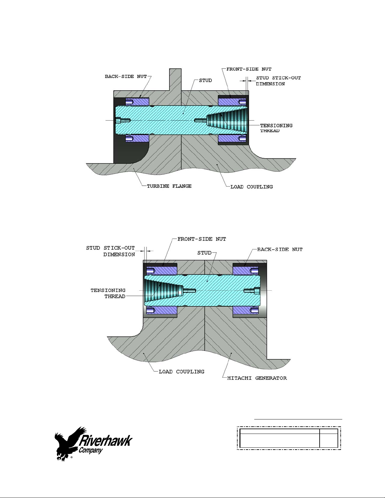
2. Assemblefront‐sidenuttothetaperedthreadend(PullEnd)ofthestud.Pleasenote
thatthefrontandbacksidenutsaredifferent.
3. Slidethestudandnutassemblyintotheflangefromthecouplingsideasshownin
Figures1and2.
4. Installthenutontheback‐sideoftheflange.Pleasenotethatthefrontandbackside
nutsaredifferent.
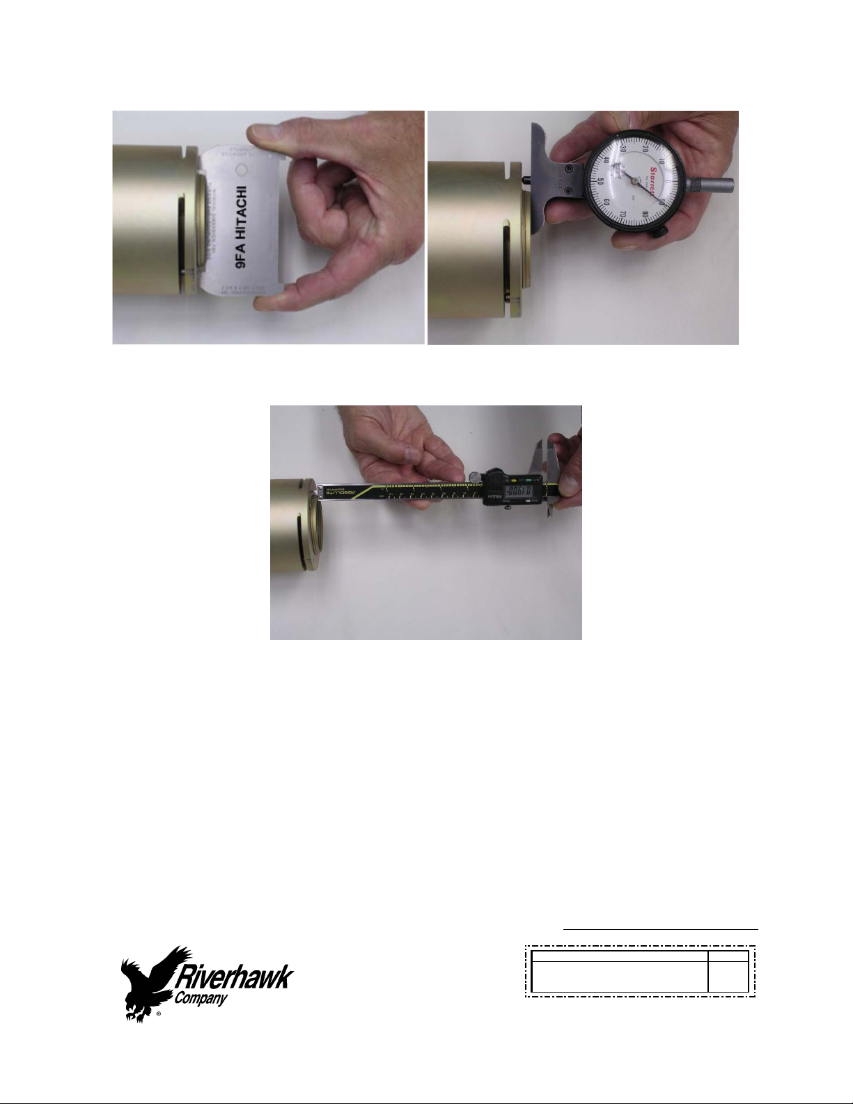
5. Adjustthenut/studassemblysothatthestudprotrudesfromthefaceofthe
cylindricalnutbytheamountdepictedonthehardwaredrawing(fromsection2)and
showninFigures1and2.SETTINGTHISPROTRUSION(orstick‐out)OFSTUDTONUT
ISCRITICALFORPROPERTENSIONEROPERATION.Ametalstick‐outgageisprovided
withthetensionertoassisttheoperatorinsettingtheprotrusiondimension(See
Figure3forthisandothermethods).
Instruction Manual IM-269
CUSTOMER'SINFORMATIONBOX
CONTENTSAREINDEPENDENTOFRIVERHAWKDOCUMENTCONTROL
215ClintonRoad
NewHartford,NY13413
Tel:+13157684855
Fax:+13157684941
Email:info@riverhawk.com
REV
373A4004
GEDRAWINGNUMBER
RevisionB
Page11of34
6. Handtightentheback‐sidenut,withoutturningthestudorfront‐sidenut,toasnugfit.
Figure1–CutawayViewofTurbineFlangeto
LoadCouplingBoltedJoint
Figure2–CutawayViewofLoadCouplingto
HitachiGeneratorBoltedJoint
Instruction Manual IM-269
CUSTOMER'SINFORMATIONBOX
CONTENTSAREINDEPENDENTOFRIVERHAWKDOCUMENTCONTROL
215ClintonRoad
NewHartford,NY13413
Tel:+13157684855
Fax:+13157684941
Email:info@riverhawk.com
REV
373A4004
GEDRAWINGNUMBER
RevisionB
Page12of34
Stick‐OutGageDropGage
DigitalCalipers
Figure3–PicturesofaStick‐OutMeasurementMethods
7.0AssemblyofHydraulicTensionerEquipment
7.1CheckHydraulicEquipment
7.1.1CheckHydraulicTensioners
Cleanpullerscrewandcheckforanydebrisanddents.
Instruction Manual IM-269
CUSTOMER'SINFORMATIONBOX
CONTENTSAREINDEPENDENTOFRIVERHAWKDOCUMENTCONTROL
215ClintonRoad
NewHartford,NY13413
Tel:+13157684855
Fax:+13157684941
Email:[email protected]
REV
373A4004
GEDRAWINGNUMBER
RevisionB
Page13of34
Pullerscrewshouldbefreetorotateandmovebackandforth.
Seambetweencylindersclosedtightly.
Inspecttensionerguardforanysignsofdamage.Bentguardsshouldbereplaced.Also,besure
therubberpadisinplaceontheendoftheguard,ifmissing,replace.
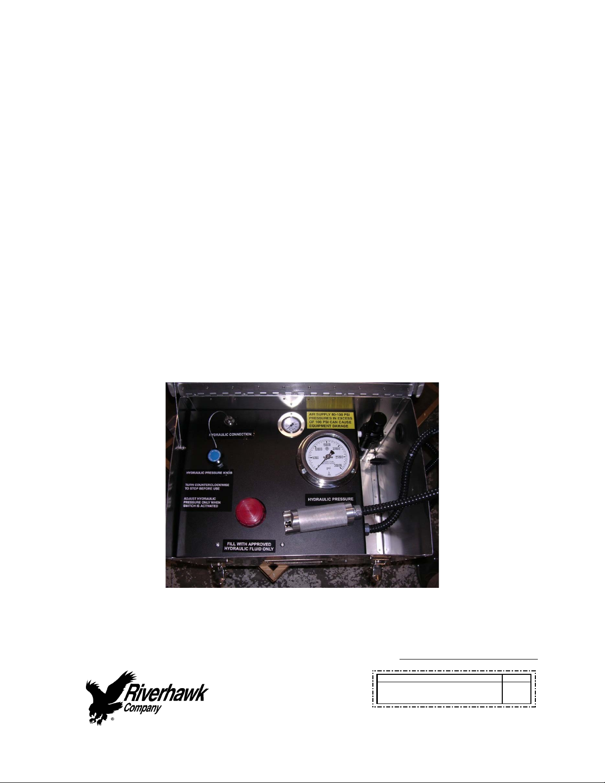
7.1.2CheckHydraulicPumpKit
Thepumpkitisshippedfullofhydraulicoil.Thepumpreservoircapissealedforshipment.
Replacethegreyshippingcapwiththeredplasticreservoircap.
Tousethepump,turncaptotheventpositionandfollowtheoperatinginstructionsonthe
insidecover.
Topreventoilspillage,closecapwhennotinuse.LostoilshouldbereplacedwithEnerpac
HydraulicOil.ISO32orequivalenthydraulicoilmaybesubstituted.
Testpumpbydead‐heading(leaveportpluginplace)andrunpump–shouldholdsteady
pressure.
SamplePictureofAP‐0532HydraulicPumpwithhydraulicconnectionpluggedfortesting
Instruction Manual IM-269
CUSTOMER'SINFORMATIONBOX
CONTENTSAREINDEPENDENTOFRIVERHAWKDOCUMENTCONTROL
215ClintonRoad
NewHartford,NY13413
Tel:+13157684855
Fax:+13157684941
Email:[email protected]
REV
373A4004
GEDRAWINGNUMBER
RevisionB
Page14of34
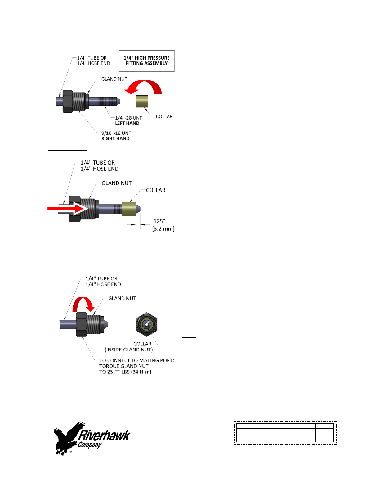
7.2HydraulicFittings
Illustration1
Riverhawkhydraulicpumpsusea1/4”High
Pressureporttoconnectitshydraulichoses.The
hoseconnectorismadefromathreepiece
assembly:aglandnut,acollar,anda1/4”tubeor
1/4”hoseend.(SeeIllustration1)
Toassemblythefitting,slidetheglandnutover
the1/4”tubeor1/4”hoseend.Turnthecollar
counter‐clockwise(lefthandthread)ontothe
tubeorhoseendasshowninIllustration1.
Illustration2
Thecollarshouldbeplaced.125”(3.2mm)from
thetipofthecone.(SeeIllustration2)Itmaybe
necessarytoadjustthiscollarwithasetofvise‐
grippliers.Becarefultonotstripthethreadsoff
thetubeorhoseend.
Illustration3
Slidetheglandnutdownoverthecollar.(See
Illustration3)Insertthe1/4”tubeor1/4”hose
endintothetensioner’squickcoupler.While
firmlyholdingthetubeorhoseendtostopitfrom
rotating,turntheglandnutclockwise(righthand
thread)andtorquetheglandnutto25FT‐LBS(34
N‐m).
Tips:
Makesureallpartsarecleanandfreefrom
debris.
Protecttheconeontheendofthe1/4”tube
or1/4”hoseendfromscratchesasthisisthe
sealingsurface.
Replaceredplasticcapswhenfinishedto
protectthethreadsandcone.

Instruction Manual IM-269
CUSTOMER'SINFORMATIONBOX
CONTENTSAREINDEPENDENTOFRIVERHAWKDOCUMENTCONTROL
215ClintonRoad
NewHartford,NY13413
Tel:+13157684855
Fax:+13157684941
Email:[email protected]
REV
373A4004
GEDRAWINGNUMBER
RevisionB
Page15of34
8.0AssemblyofTensioneronStud
CAUTION
The “9FA gas turbine to the load coupling” flange uses a different tensioner than the “load
couplingtoHITACHIgenerator”flange.Verifythecorrecttensionerisbeingused
RiverhawktensionerHT‐0445isfortheGASTURBINESIDEONLY.
RiverhawktensionerHT‐5407isfortheGENERATORSIDEONLY.
8.1HandlingoftheTensioner
Restthetensionerontopofthecouplingshaft.Usingastrapjustlongenoughtogoaroundthe
couplingshaft,attacheachendtothehandlesofthetensioner.Onewaytodothisistoattach
thestrapbyloopingthestrapthroughitselfandaroundthehandleofthetensionerononeside
thenaroundthecouplingshaftandfinallyattachedtothehandleontheothersidewithaD‐
shackle.Thiswillhelpholdthetensionerinplaceshoulditfalloffoftheshaft.Thestrapalso
helpstheoperatorsmovethetensioneraroundtheshaftwhiletensioning.
Ifpossible,usea‘Come‐along’orchainfallfromtheceilingofthecouplingroomandattachit
tothetensionerusingashortstrapwrappedthroughthehandlesandaroundthetopofthe
tensioner.Thiswillallowtheoperatorstoeasilymovethetensioneraroundthecouplingshaft
bysupportingtheweightofthetool.
8.2KitAssembly
Assemblethehydraulicpumpwithitshosetothetensionerandbleedouttheairperfollowing
instructionsinsection8.3.

Instruction Manual IM-269
CUSTOMER'SINFORMATIONBOX
CONTENTSAREINDEPENDENTOFRIVERHAWKDOCUMENTCONTROL
215ClintonRoad
NewHartford,NY13413
Tel:+13157684855
Fax:+13157684941
Email:[email protected]
REV
373A4004
GEDRAWINGNUMBER
RevisionB
Page16of34
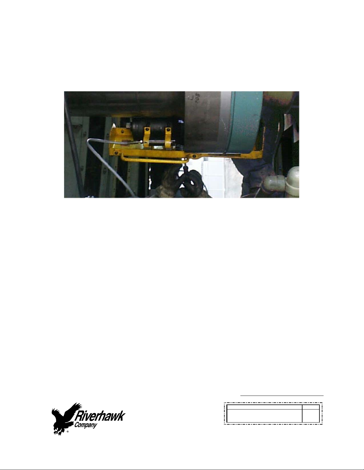
Samplepictureshowinghoseattachedtoatensioner
Note:Beforethreadingthepullerscrewintothestud,carefullycheckthecleanlinessofboth
thestud'sandthepullerscrew'sconicalthreads.Applyalightcoatofcleanturbineoilora
spraylubricanttothepullerscrew.Donotuse“NeverSeize”ontheconicalthreads.This
procedurewilleaseassemblyandassurepositivematingofthethreadsbeforetightening.
RefertoTensionerAssemblydrawingandphotoforviewsofthetensionertoflangemounting.
Alltensioningwillbeperformedonthecouplingsideoftheflangeconnections.

Instruction Manual IM-269
CUSTOMER'SINFORMATIONBOX
CONTENTSAREINDEPENDENTOFRIVERHAWKDOCUMENTCONTROL
215ClintonRoad
NewHartford,NY13413
Tel:+13157684855
Fax:+13157684941
Email:info@riverhawk.com
REV
373A4004
GEDRAWINGNUMBER
RevisionB
Page17of34
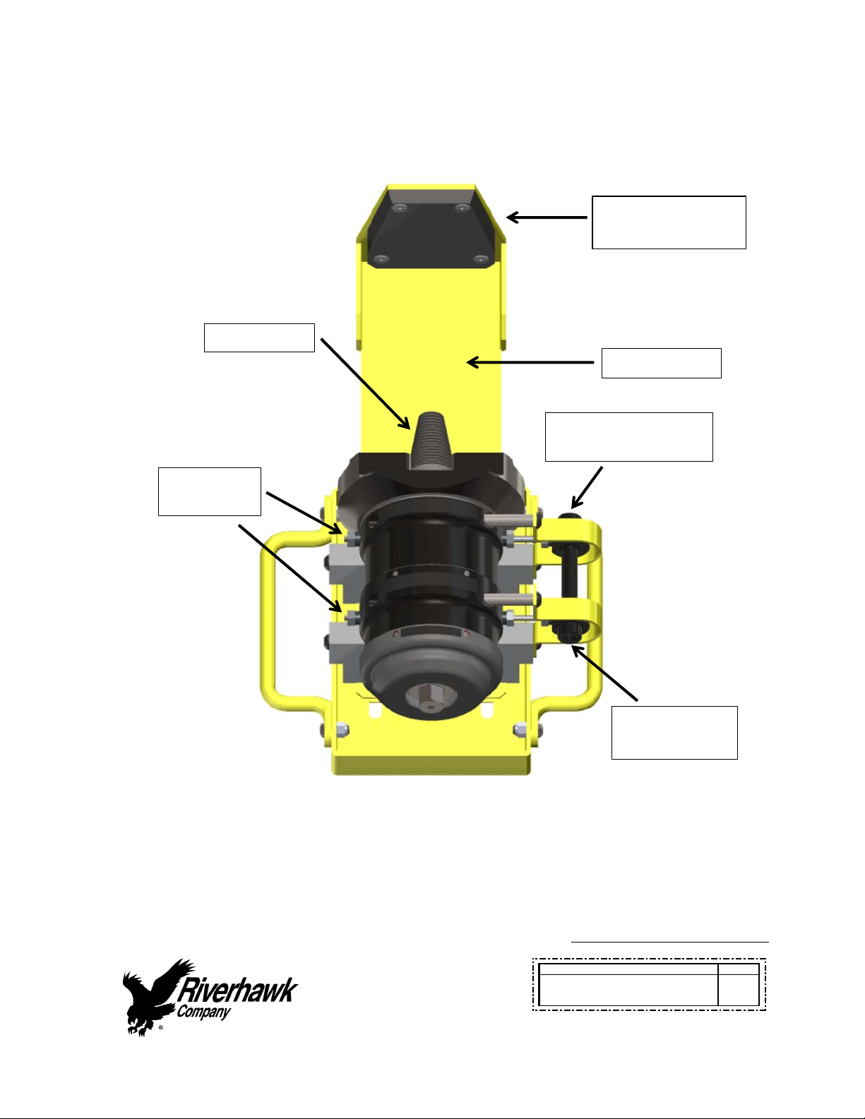
FigureofHT‐0445Tensioner
RubberPad
(DONOTREMOVE)
SafetyGuard
PullerScrew
PressureReliefValve
withBurstDisc
HydraulicHose
Connection
Hydraulic
Bl
eed
P
o
r
ts
Instruction Manual IM-269
CUSTOMER'SINFORMATIONBOX
CONTENTSAREINDEPENDENTOFRIVERHAWKDOCUMENTCONTROL
215ClintonRoad
NewHartford,NY13413
Tel:+13157684855
Fax:+13157684941
Email:info@riverhawk.com
REV
373A4004
GEDRAWINGNUMBER
RevisionB
Page18of34
FigureofHT‐5407Tensioner
RubberPad
(DONOTREMOVE)
SafetyGuard
PressureReliefValve
withBurstDisc
HydraulicHose
Connection
PullerScrew
Hydraulic
Bl
eed
P
o
r
ts
Instruction Manual IM-269
CUSTOMER'SINFORMATIONBOX
CONTENTSAREINDEPENDENTOFRIVERHAWKDOCUMENTCONTROL
215ClintonRoad
NewHartford,NY13413
Tel:+13157684855
Fax:+13157684941
Email:info@riverhawk.com
REV
373A4004
GEDRAWINGNUMBER
RevisionB
Page19of34
Assemblysequenceisasfollows:
Placethespannerring(differentforeachendturbineorgenerator)overthepuller
screwonthetensioner.
Placeandholdthetensionerassemblyovertheendofthestudtobetightened.
Slidethepullerscrewintothetaperedthreadofthestudandhandtighten.Besurenot
tocrossthreadassembly.
Holdthestudsteadywitha1/2”hexkeywrenchandlightlytightenthepullerscrewinto
theconicalthreadofthestudwithawrench.
Placethespannerringonthecylindricalnutlocatedonthestud.
AtthispointtheTensionerAssemblyMUSTBEFREETOROTATE,thepullerscrewmust
betightinthestud.DONOTBACKOFFPULLERSCREW.
Ifthetensionerisnotfreetorotatewhenthepullerscrewistightthen,either(1)thestudis
notproperlypositionedintheflangeandrecheckthestick‐outlengthandrepositionthenuts,
or(2)Thetensionerisdamagedandmustbereturnedforrepair.
CAUTION
Personalinjuryandequipmentdamagecanoccurifthepullerscrewisnotsecurelyengaged
withthetaperedthreadofthestud.Properengagementisachievedwhenthepullerscrewis
tightinthestudandtheTensionerAssemblyisfreetorotate.
8.3BleedingHydraulicSystem
FollowthetensionerassemblyinstructionsofSection8.0

Instruction Manual IM-269
CUSTOMER'SINFORMATIONBOX
CONTENTSAREINDEPENDENTOFRIVERHAWKDOCUMENTCONTROL
215ClintonRoad
NewHartford,NY13413
Tel:+13157684855
Fax:+13157684941
Email:[email protected]
REV
373A4004
GEDRAWINGNUMBER
RevisionB
Page20of34
TOAVOIDFAILURE,ENSURESAFETYANDPROPEROPERATIONTHETENSIONERASSEMBLY
MUSTBEMOUNTEDONTHESTUDBEFOREBLEEDINGTHESYSTEMANDTENSIONINGBEGINS.
Thetensionerhasfourports,oneforpressurizing,twoforbleedingthesystemandafourth
pressurereliefport.Tofacilitatebleeding,startbyfirstmountingthetensioneratthe9o’clock
studposition.Also,makesurethatthepumpisalwayssituatedbelowthetensionerassembly.
Thetensionerisequippedwith5/8"hexconedstembleederfittingsinstalledinthebleeder
ports.Withthesetwofittingsloosenedsimultaneously,strokethepumprepeatedlyuntilthe
streamsofoilexitingthetoolfromeachportarefreeofair,thenretightenthefittings.
Note:Thehoseisstiff;useofthistoolingcanbesimplifiedbytemporarilymountingthe
tensionerononestudpriortofinaltighteningoffittings.Thiswillreducethetendency
forthefittingstoloosenduringuse.
9.0StudTensioning
Thestudswillbetensionedintwosteps,at50%pressureandatfinalpressure.Followthe
tensioningsequenceforeachflangejointasdefinedonthedatasheetsfoundattheendofthis
manual
WARNING
ThesafetycageMUSTbeinplaceandhandskeptoutofdesignatedareasatalltimeswhenthe
tensionerispressurizedotherwisepersonalinjurycanoccur.
9.1Tensioningat50%pressure
Afterthetensionerisproperlyinstalledapplyhydraulicpressuretothetool.Bringthepressure
tothe50%levelinaccordancewiththefollowingtable.
FlangePosition StudSize 50%Pressure 50%Stretch
TurbinetoCoupling 2‐3/4"
[71mm]
10000psi
[690bar]
Donotmeasure
Donotuse
CouplingtoGenerator 2‐3/4"
[71mm]
8000psi
[550bar]
Donotmeasure
Donotuse
Table of contents
Other riverhawk Industrial Equipment manuals

riverhawk
riverhawk IM-186 User manual

riverhawk
riverhawk IM-125 User manual

riverhawk
riverhawk IM-164 User manual

riverhawk
riverhawk IM-255 User manual

riverhawk
riverhawk IM-477 User manual

riverhawk
riverhawk IM-150 User manual

riverhawk
riverhawk IM-139 User manual

riverhawk
riverhawk IM-278 User manual

riverhawk
riverhawk IM-257 User manual

riverhawk
riverhawk IM-116 User manual


