riverhawk IM-116 User manual
Repairs – Rentals
Field Service
215ClintonRoad
NewHartford,NY13413
Tel:+13157684855
Fax:+13157684941
Email:[email protected]
RevisionH
Page1of29
INSTRUCTIONMANUALIM‐116
ForGasTurbineTensionedStudsandNuts
Fr.9ETurbineto9A3ELINGeneratorGE358A7202P022
GEPower&Water
GENERALELECTRICCOMPANY
MLI: ____ OF ____
DATE
CUSTOMER'SINFORMATIONBOX
CONTENTSAREINDEPENDENTOFRIVERHAWKDOCUMENTCONTROL
ISSUED:
THISDOCUMENTSHALLBEREVISEDINITSENTIRETY.ALLSHEETSOFTHISDOCUMENTARE
THESAMEREVISIONLEVELASINDICATEDINTHISVENDORSUPPLIEDDRAWINGAPPLIQUE.
REV
373A4028
GEDRAWINGNUMBER
VENDORSUPPLIED
THISDOCUMENTISFILEDUNDERTHEGEDRAWINGNUMBER.
GENOTTOREVISE.GEREVISIONLEVELISSHOWNONTHISAPPLIQUE.
GESIGNATURES
CHECKED:
TheRiverhawkCompanyreservestherighttoupdatethisdocumentwithoutdisseminationornotice.The
latestrevisionmaybeobtainedbycontactingRiverhawkCompanyorthruwww.riverhawk.com.

InstructionManualIM‐116
CUSTOMER'SINFORMATIONBOX
CONTENTSAREINDEPENDENTOFRIVERHAWKDOCUMENTCONTROL
215ClintonRoad
NewHartford,NY13413
Tel:+13157684855
Fax:+13157684941
Email:[email protected]
REV
373A4028
GEDRAWINGNUMBER
RevisionH
Page2of29
TableofContents
Section Description PageNumber
1.0 CautionsandSafetyWarnings 3
2.0 Scope 4
3.0 QuickCheck‐List 4
4.0 GeneralPreparations 7
5.0 HardwareSetPreparations 8
6.0 StudandNutAssembly 10
7.0 AssemblyofHydraulicTensionerEquipment 10
8.0 AssemblyofTensioneronStud 12
9.0 StudPullingandTensioning 13
10.0 ThreadLocking 15
11.0 Stud/NutRemoval 15
12.0 FrequentAskedQuestions 16
13.0 RevisionHistory 18
AppendixA1 ECDeclarationofConformity 19
AppendixA2 UKCADeclarationofConformity 20
AppendixB 16‐BoltTensioningPatternRecordSheet 29

InstructionManualIM‐116
CUSTOMER'SINFORMATIONBOX
CONTENTSAREINDEPENDENTOFRIVERHAWKDOCUMENTCONTROL
215ClintonRoad
NewHartford,NY13413
Tel:+13157684855
Fax:+13157684941
Email:[email protected]
REV
373A4028
GEDRAWINGNUMBER
RevisionH
Page3of29
1.0CautionsandSafetyWarnings
WARNING
Impropertooluseandthefailuretofollowthecorrectproceduresaretheprimaryrootcauses
oftoolfailuresandpersonalinjuries.Alackoftrainingorexperiencecanleadtoincorrect
hardwareinstallationorincorrecttooluse,onlytrainedoperatorswithcareful,deliberate
actionshouldusehydraulictensioners.ContactRiverhawkCompanywithanytrainingneeds.
CAUTION
Personalinjuryandequipmentdamagecanoccurifthepullerscrewisnotsecurelyengaged
withthetaperedthreadofthestud.Properengagementisachievedwhenthepullerscrewis
tightinthestudandtheTensionerAssemblyisfreetorotate.
WARNING
Riskofhighpressurehydraulicfluidinjection.Riverhawktoolsoperateunderhighpressure.
Thoroughlyinspectallhosesandconnectionsfordamageorleakspriortousingthisequipment.
WARNING
Theproperpersonalprotectiveequipmentmustbewornatalltimes.Riverhawkrecommends
ataminimum,safetyglasses,longsleeveshirt,hardhat,heavyworkgloves,andsteeltoe
shoes.
WARNING
ThesafetycageMUSTbeinplaceandhandskeptoutofdesignatedareasatalltimeswhenthe
tensionerispressurizedotherwisepersonalinjurycanoccur.
CAUTION
DONOTEXCEEDTHEMAXIMUMPRESSUREVIBROSCRIBEDONTHEPULLERBODY.Excessive
pressurecandamagethestudandthepullerscrew.
WARNING
FireHazard!DONOTheatwhenthepullerassemblyisinplace.Personalinjuryorequipment
damagemayoccur.UseofanOxy‐Acetylenetorchisnotrecommended.
NOTICE
DonotusemorethreadlockingcompoundthanspecifiedorthenutmaybeVERYdifficultto
removeatdisassembly.
CAUTION
DONOTEXCEEDTHEMAXIMUMPRESSUREVIBROSCRIBEDONTHEPULLERBODY.Excessive
pressurecandamagethestudandpullerscrew

InstructionManualIM‐116
CUSTOMER'SINFORMATIONBOX
CONTENTSAREINDEPENDENTOFRIVERHAWKDOCUMENTCONTROL
215ClintonRoad
NewHartford,NY13413
Tel:+13157684855
Fax:+13157684941
Email:[email protected]
REV
373A4028
GEDRAWINGNUMBER
RevisionH
Page4of29
Note:Beforethreadingthepullerscrewintothestud,carefullycheckthecleanlinessofboth
thestud'sandthepullerscrew'sconicalthreads.Applyalightcoatofcleanturbineoilora
spraylubricanttothepullerscrew.Donotuse“NeverSeize”ontheconicalthreads.This
procedurewilleaseassemblyandassurepositivematingofthethreadsbeforetightening.
2.0 Scope
Thisdocumentdescribestheproceduretobeusedtoinstallstudsandnutssuppliedby
RiverhawkCompanyintheflangesattheturbine/couplingandcoupling/generatorconnections.
ThishardwareisdepictedonthefollowingdrawingsThesedrawingsaswellasthetooling
drawingsformapartofthismanual.
HF‐0813
3.0QuickChecklist
ThefollowingchecklistisintendedasasummaryofthestepsneededtousetheRiverhawk‐
suppliedequipment.Newpersonnelorthoseexperiencedpersonnelwhohavenotusedthe
Riverhawkequipmentrecentlyareencouragedtoreadtheentiremanual.
EQUIPMENTINSPECTION
□Checkoillevelinhydraulicpump.
□Checkairpressureat80psi[5.5bar]minimum.(Forair‐drivenpumps)
□Checkhydraulichosefordamage.
□Testpump.
□Inspecttensionerforanydamage.
NUTANDSTUDPREPARATION
□Inspectstudandnutsforanydamage.

InstructionManualIM‐116
CUSTOMER'SINFORMATIONBOX
CONTENTSAREINDEPENDENTOFRIVERHAWKDOCUMENTCONTROL
215ClintonRoad
NewHartford,NY13413
Tel:+13157684855
Fax:+13157684941
Email:[email protected]
REV
373A4028
GEDRAWINGNUMBER
RevisionH
Page5of29
□Measurestudlength.
□Cleanthestudsandnuts.
□Installstudsandnuts(off‐center)intotheflange.
□Setstick‐outdimensiononthecouplingsideoftheflange.
□Handtightenallstuds.
□Verifystick‐outmeasurement(VERYIMPORTANT)
Tensioning(Boltinstallation)
□Matchthetensionersetuptotheflangejoint.
□Applyalightcoatofcleanturbineoilorspraylubricanttothepullerscrew.DONOTUSE
“NEVERSEIZE”ONTHECONICALTHREADS.
□Slidespannerringoverthepullerscrew.
□Mountthetensioneronthestudinflange.
□Installspannerringontonut.
□Insert1/2”hexAllenwrenchintothebacksideofthestud.
□Tightenthepullerscrew.
□Backoffpullerscrew1/2turn.
□Retightenthepullerscrewandleavetight.DONOTBACKOFFPULLERSCREW.
□Bleedthetensioner.DoNOTbleedtensioneroffofastud!Damagetothetoolwill
result!
□Tensionto50%.Consultmanualforcorrectpressure.

InstructionManualIM‐116
CUSTOMER'SINFORMATIONBOX
CONTENTSAREINDEPENDENTOFRIVERHAWKDOCUMENTCONTROL
215ClintonRoad
NewHartford,NY13413
Tel:+13157684855
Fax:+13157684941
Email:[email protected]
REV
373A4028
GEDRAWINGNUMBER
RevisionH
Page6of29
□Usethepinwrenchinspannerringtotightennut.
□Releasepressure,movetonextstudinpattern.
□Repeatabovestepsatfinalpressure.
□Measurefinalstudlengthandrecordonstretchdatasheets.Calculatestretch.
□Torquenuts'setscrews.
Detensioning(Studremoval)
□Loosennuts'setscrews
□Inspectandcleanstuds'conicalthreads.DonotcontinueuntilALLdebrisisremoved
fromthethreads!Donottrytousethetensionertoremoveadamagedstud!
□Applyalightcoatofcleanturbineoilorspraylubricanttothepullerscrew.DONOTUSE
“NEVERSEIZE”ONTHECONICALTHREADS.
□Slidespannerringoverthepullerscrew.
□Mountthetensioneronthestud.
□Installspannerringintonut.
□Tightenthepullerscrew.
□Backoffpullerscrew1/2aturn.
□Retightenthepullerscrewandleavetight.DONOTBACKOFFPULLERSCREW.
□Bleedthetensioner.DoNOTbleedtensioneroffofastud!Damagetothetoolwill
result!
□Applyfinalpressure.

InstructionManualIM‐116
CUSTOMER'SINFORMATIONBOX
CONTENTSAREINDEPENDENTOFRIVERHAWKDOCUMENTCONTROL
215ClintonRoad
NewHartford,NY13413
Tel:+13157684855
Fax:+13157684941
Email:[email protected]
REV
373A4028
GEDRAWINGNUMBER
RevisionH
Page7of29
□Loosennutwiththespannerringandpinwrench.
□Movetonextstudinpattern
4.0GeneralPreparations
Readandunderstandallinstructionsbeforeinstallingstuds.
Thisequipmentproducesveryhighhydraulicpressuresandveryhighforces.Operatorsmust
exercisecaution,wearsafetyglassesandhardhatswhenusingthisequipment.
HighpressurefluidfromtheHydraulicPressureKitsystempressurizesthetensionerwhich
generatesastretchingforcethatactuallystretchesthestud.Asthestudisstretchedthenut
liftsofftheflange.Thenutisthenreseatedintopositionontheflangebyturninganutdriver
byhand.Whenthenutistightagainsttheflange,thepressureinthetensionerisreleased
leavingthestudloadedtoitspredeterminedvalue.
4.1MachinePreparation
Theflangetobetensionedmustbefullyclosedpriortopositioningofstudsintheflanges.
Theremustbeprovisiontoturntheshaftsoftheturbineandthegenerator.Also,itwillbe
advantageoustoremoveasmanyobstructionsaspossiblefromtheflangearea,suchasspeed
probesandconduit.
4.2Hardware–Balance
Hardwareissuppliedasweightbalancedsets
StudsandNutsareinterchangeablewithinsets
Donotmixwithothersets
Saveweightcertificationforthepurchaseofspares
4.3Tensioner–CareandHandling
Whennotinuse,thetensionershallbemaintainedinacleanenvironmentandallcapsand
plugsforhydraulicopeningsandfittingsmustbeinplace.
UseISO32gradeoil.
Wheninuse,thetensionershallbeprotectedfromsandandgrit

InstructionManualIM‐116
CUSTOMER'SINFORMATIONBOX
CONTENTSAREINDEPENDENTOFRIVERHAWKDOCUMENTCONTROL
215ClintonRoad
NewHartford,NY13413
Tel:+13157684855
Fax:+13157684941
Email:[email protected]
REV
373A4028
GEDRAWINGNUMBER
RevisionH
Page8of29
Longtermstorage–coattensionerwithoil,returntooriginalcontainer,sealcontainerand
protectfrommoisture
Shipment–coattensionerwithoilandshipinoriginalcontainer
4.4 HandTools
Severalhandwrenchesandmicrometerswillberequiredtoperforminstallationand
measurementofthestuds:
5/8”wrench
1"wrench
1”socketandimpactwrench
AsetofAllenWrenches
3’–4’BreakerBar
9”to10”micrometerorcaliper
10”to11”micrometerorcaliper
4.5SpecialTools
HydraulicTensionerKit: HT‐0814HydraulicTensioner
HydraulicPumpKit: AP‐0532Air‐OperatedHydraulicPump
(recommended)
(referenceGE359B2502)
MP‐0130ManualHand‐Operated
HydraulicPump
(referenceGE359B2506)
5.0HardwareSetPreparations
5.1NutPreparation
Fornewinstallations,thenutsshouldcomesealedfromthefactoryandwillneednocleaning.
Previouslyinstallednutsrequirecleaningasfollows:Wirebrushusingapetroleum‐based
solventtoremoveanyforeignmaterialontheexternalsurfacesandthreads.
Ifpreviousinstallationsemployedathreadlockingcompound,whichwillbevisibleasagrayish‐
greenresidue,removeasmuchofthiscompoundaspossible.
InstructionManualIM‐116
CUSTOMER'SINFORMATIONBOX
CONTENTSAREINDEPENDENTOFRIVERHAWKDOCUMENTCONTROL
215ClintonRoad
NewHartford,NY13413
Tel:+13157684855
Fax:+13157684941
Email:[email protected]
REV
373A4028
GEDRAWINGNUMBER
RevisionH
Page9of29
Donotapplythreadlubricantstothethreads.
Finishthecleaningprocessbyrinsinginavolatilesolventsuchasacetoneandallowtodry.
5.2StudPreparation
Fornewinstallations,thestudsshouldcomesealedfromthefactoryandwillneednocleaning.
5.2.1StudCleaning‐OldInstallations
Previouslyinstalledstudsmayrequirecleaning.Cleanconicalthreadsshouldhaveabrightand
shinyappearance.
Ifcleaningisrequired,followthesesteps:
1. Blowoutthethreadswithcompressedairtoremoveloosedebrisanddryconical
threads.Donotapplyasolventorothercleaningsolutiontothethreadsasthismay
chemicallyattackthestud.
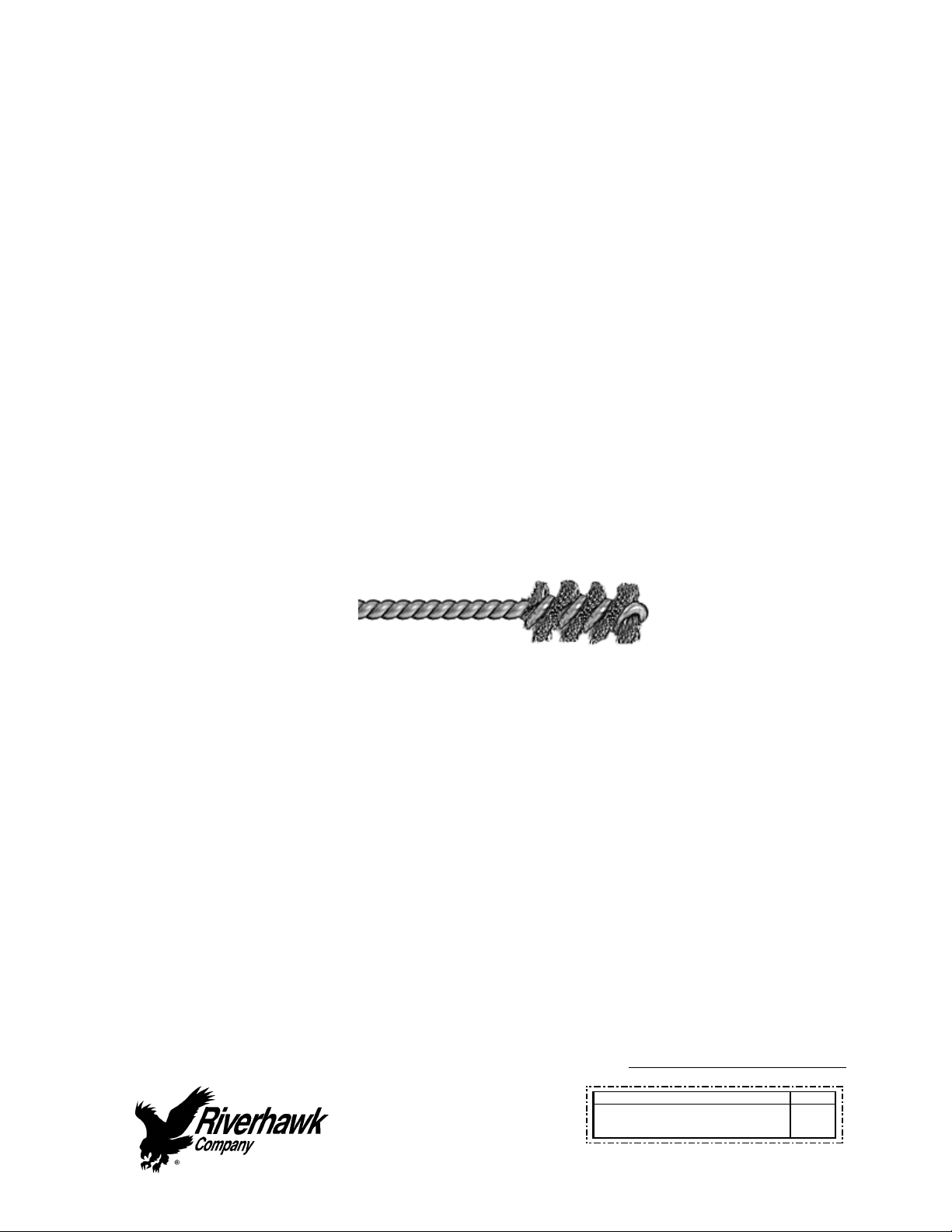
2. UseStudCleaningKit,GT‐4253orasimilar1"diameterBrasspowerbrush.
PictureofBrassPowerBrush
3. Insertthebrushintoanelectricdrillandsetdrilltoruninacounterclockwisedirection
athighspeed.
4. Workthedrillinacircularmotionwhilemovingthebrushinandouttocleanallofthe
threads.Trynottoholdthebrushinoneplacetoolong,soasnottoremovethestud's
protectivecoating.
5. Blowoutthethreadswithcompressedairtoremovelooseneddebris.
6. Visuallyinspectthreadsforcleanliness.Threadsshouldbebrightandshiny.
7. Repeatifanydirtcanbeseeninthethreads.
8. Inspectthreadsforanydamagethatmayhavebeencausedbypreviousinstallation.

InstructionManualIM‐116
CUSTOMER'SINFORMATIONBOX
CONTENTSAREINDEPENDENTOFRIVERHAWKDOCUMENTCONTROL
215ClintonRoad
NewHartford,NY13413
Tel:+13157684855
Fax:+13157684941
Email:[email protected]
REV
373A4028
GEDRAWINGNUMBER
RevisionH
Page10of29
Donotapplythreadlubricantstothethreads.
Finishthecleaningprocessbyrinsinginavolatilesolventsuchasacetoneandallowtodry.
5.3StudLengthMeasurement
Measureandrecordtheinitiallengthsofthestuds.Thefollowingrecommendationswill
improveyourresults.
Plantostartandfinishanyflangeinthesameday.
Studsandflangemustbeatthesametemperature.
Numbereachstudwithamarker.
Markthelocationofmeasurementonstudendwithapermanentmarker.
Measureeachstudtonearest0.001inch.
Recordeachmeasurementonthesuppliedcharts.
Donotallowthemeasuringinstrumentstosetinthesun.
6.0StudandNutAssembly
Refertohardwareassemblydrawing(HF‐0813)listedinSection2.0ofthismanual.
1. Assemblecylindricalnuttothetaperedthreadend(PullEnd)ofthestud.
2. SlidethestudandcylindricalnutassemblyintotheflangeasshowninFigures1&2and
installtheothernutonthebackside.
3. Adjustthenut/studassemblysothatthestudprotrudesfromthefaceofthe
cylindricalnuttheamountasdepictedonthehardwaredrawing(HF‐0813).SETTING
THISPROTRUSIONOFSTUDTONUTISCRITICALFORPROPERTENSIONEROPERATION.
4. Hand‐tightentheassemblytoasnugfit.Seephotos1&2forviewofstudsinflange
priortotensioning.
7.0AssemblyofHydraulicTensionerEquipment
7.1KitAssembly
Assemblethehydraulicpumpwithitshosetothepullertoolandbleedthesystemofairper
followinginstructions.Photo4showshoseconnectedtomanifoldoftensioner.
Cleanpullerscrewandcheckforanydebrisanddents.

InstructionManualIM‐116
CUSTOMER'SINFORMATIONBOX
CONTENTSAREINDEPENDENTOFRIVERHAWKDOCUMENTCONTROL
215ClintonRoad
NewHartford,NY13413
Tel:+13157684855
Fax:+13157684941
Email:[email protected]
REV
373A4028
GEDRAWINGNUMBER
RevisionH
Page11of29
Pullerscrewshouldbefreetorotateandmovebackandforth.
Seambetweencylindersclosedtightly.
Inspecttensionerguardforanysignsofdamage.Bentguardsshouldbereplaced.Also,besure
therubberpadisinplaceontheendoftheguard,ifmissing,replace.
7.1.1Fittings
Makesurebothmaleandfemalepartsarecleanandfreeofdebris,seeFigure3forfitting
configuration.Holdfemalepartsecurelywhentighteningsoastopreventdamagetoadjacent
tubing.Iffittingleaksfirsttryretighteningasneeded.Ifleakingcontinuesthendisassemble
andcheckforscratchesordebrisontheseatingconicalsurfaces.Cleanasrequired.Replace
plasticcapswhenfinishedwithtooling.
7.2Pump
Thepumpkitisshippedfullofhydraulicoil.Thepumpreservoircapissealedforshipment.To
useturncaptotheventposition.Topreventoilspillageclosecapwhennotinuse,during
storageandshipment.LostoilshouldbereplacedwithEnerpacHydraulicOil.ISO32.Mineral
Oilmaybesubstituted,ifnecessary.
7.3BleedingHydraulicSystem
FollowthetensionerassemblyinstructionsofSection8.0.
TOAVOIDFAILURE,ENSURESAFETYANDPROPEROPERATIONTHETENSIONERASSEMBLY
MUSTBEMOUNTEDONTHESTUDBEFOREBLEEDINGTHESYSTEMANDTENSIONINGBEGINS.
ThetensionerhasfourportsseeFig.5,oneforpressurizing,twoforbleedingthesystemanda
fourthpressurereliefport.
Tofacilitatebleeding,startbyfirstmountingthetensionerateitherthe30’clockor9o’clock
studpositiondependingonwhichwillcriticallyplacethebleedportsintheiruppermost
position.Inaddition,makesurethatthepumpisalwayssituatedbelowthetensionerassembly.
Thepullertoolisequippedwith5/8in.[16mm]Hexconedstembleederfittingsinstalledinthe
bleederports.Withthesestwofittingsloosenedsimultaneously,strokethepumprepeatedly
untilthestreamsofoilexitingthetoolfromeachportarefreeofair,thenretightenthefittings.

InstructionManualIM‐116
CUSTOMER'SINFORMATIONBOX
CONTENTSAREINDEPENDENTOFRIVERHAWKDOCUMENTCONTROL
215ClintonRoad
NewHartford,NY13413
Tel:+13157684855
Fax:+13157684941
Email:[email protected]
REV
373A4028
GEDRAWINGNUMBER
RevisionH
Page12of29
Providingthatthehoseisnotdisconnectedorloosenedintheprocessoftensioningallthe
studs,bleedingtheassemblyonceatthefirstpositionshouldsufficetofilltheassemblyand
precludetheneedtorepeatthebleedingprocess.
Note:Thehoseisstiff,useofthistoolingcanbesimplifiedbytemporarilymountingthepuller
toolononestudpriortofinaltighteningoffittings.Thiswillreducethetendencyforthe
fittingstoloosen.
8.0AssemblyofTensioneronStud
Alltensioningwillbeperformedfromthetaperedthreadendofthestudwithorientationof
thestudtotheflangeasshowninFigures1&2.RefertoTensionerassemblydrawingand
Figure5fortensionertoflangemounting.
Thisassemblyhasthefollowingfeatureswhichshouldmakestudtensioningsafeandeasy.
Thesafetycageisintegral(bolted)tothepullertool
Thehydraulicpistonisspringloadedtoretract.
Thepullerscrewisa2‐piecedesignwhichrequiresthattheoperatortightenthepuller
screwintothestud.
Assemblysequenceisasfollows:
1. Openthehydraulicreturnvalveonthehandpumptoallowhydraulicfluidtobepushed
backfromthepullertoolintothepumpreservoir.(Thisisautomaticwiththeair‐operated
hydraulicpump)
2. Placethespannerringonthepullersidecylindricalnut
3. Applyalightcoatofcleanturbineoiloraspraylubricanttothepullerscrew.Donotuse
“NeverSeize”ontheconicalthreads.
4. Placeandholdthetensionerassemblyovertheendofthestudtobetightened.See
photos3,4&5.
5. Slidethepullerscrewintothetaperedthreadofthestudandhandtighten.Besurenotto
crossthreadassembly.
6. TightenthepullerscrewusingAllenwrenchesonthepullerscrewandthestud.DONOT
wrenchonthenutoppositethepullertool.
7. AtthispointtheTensionerAssemblyMUSTBEFREETOROTATE,thepullerscrewmustbe
tightinthestudandthepullernuthasbeenbacked‐off2flats.

InstructionManualIM‐116
CUSTOMER'SINFORMATIONBOX
CONTENTSAREINDEPENDENTOFRIVERHAWKDOCUMENTCONTROL
215ClintonRoad
NewHartford,NY13413
Tel:+13157684855
Fax:+13157684941
Email:[email protected]
REV
373A4028
GEDRAWINGNUMBER
RevisionH
Page13of29
Ifthepullertoolisnotfreetorotatewhenthepullerscrewistight,theneither.(1)The
tensionerisdamaged,or.(2)Thestudisnotproperlypositionedintheflangeandthenuts
mustrepositioned.Thiscanbedoneasfollows.
1. Slightlyloosenthepullerscrew
2. Backthenutoppositethepullertooloffabout1/2turn
3. Tightenthepullerscrewsidenuttotakeuptheslack.
4. Retightenthepullerscrewperaboveandcheckforloosenessoftool
CAUTION
Personalinjuryandequipmentdamagecanoccurifthepullerscrewisnotsecurelyengaged
withthetaperedthreadofthestud.Properengagementisachievedwhenthepullerscrewis
tightinthestudandtheTensionerAssemblyisfreetorotate.
9.0StudPullingandTensioning
Thestudswillbetensionedintwosteps,atapproximately50%pressureandatfinalpressure.
Followthetensioningsequenceforeachflangejointasdefinedonthedatasheetsfoundatthe
endofthismanual
Note:Beforethreadingthepullerscrewintothestud,carefullycheckthecleanlinessofboth
thestud'sandthepullerscrew'sconicalthreads.Applyalightcoatofcleanturbineoilora
spraylubricanttothepullerscrew.Donotuse“NeverSeize”ontheconicalthreads.This
procedurewilleaseassemblyandassurepositivematingofthethreadsbeforetightening.
WARNING
ThesafetycageMUSTbeinplaceandhandskeptoutofdesignatedareasatalltimeswhenthe
pullertoolispressurizedotherwisepersonalinjurycanoccur.
9.1Tensioningat50%pressure
Afterthetensionerisproperlyinstalledapplyhydraulicpressuretothetool.Bringthepressure
tothe50%levelinaccordancewiththefollowingtable.

InstructionManualIM‐116
CUSTOMER'SINFORMATIONBOX
CONTENTSAREINDEPENDENTOFRIVERHAWKDOCUMENTCONTROL
215ClintonRoad
NewHartford,NY13413
Tel:+13157684855
Fax:+13157684941
Email:[email protected]
REV
373A4028
GEDRAWINGNUMBER
RevisionH
Page14of29
FlangePosition StudSize 50%Pressure 50%Stretch
TurbinetoCoupling 2.784"
[71mm]
9000psi
[620bar]
Donotmeasure
Donotuse
CouplingtoGenerator 2.283"
[58mm]
10000psi
[690bar]
Donotmeasure
Donotuse
9.1.1TighteningtheTurbine/CouplingandCoupling/GeneratorNuts
TurnthecylindricalnutusingthespannerringandpinwrenchasdepictedinFigure5untilit
bottomsontheflange.
9.2RemovingtheTensionerfromanInstalledStud
Pullertoolremovalistoaccomplishedasfollows:
1. Releasethepullertoolpressurebyopeningthevalveonthepump.Leavethevalve
open.Thisisautomaticontheair‐operatedhydraulicpump.
2. Unscrewthepullerscrewusingawrench
3. Tappingthewrenchwithahammermaybenecessarytoloosenthepullerscrew.
4. Movethetooltothenextstud/nutassemblytobetensioned,followingthe
sequence/patternasdefinedonthesupplieddatasheets.
9.3TensioningatFinalPressure
Repeatthepullingandtighteningprocedurestatedaboveatfullpressure.Measuresthelength
ofthestudsafterallhavebeentensioned.Thefinalpressureandrequiredstretchvaluesare
listedinthefollowingtable
FlangePosition StudSize FinalPressure FinalStretch
TurbinetoCoupling 2.784"
[71mm]
18000psi
[1170bar]
0.011"‐0.014"
[0.28mm‐0.36mm]
CouplingtoGenerator 2.283"
[58mm]
20500psi
[1240bar]
0.019"‐0.023"
[0.48mm‐0.58mm]

InstructionManualIM‐116
CUSTOMER'SINFORMATIONBOX
CONTENTSAREINDEPENDENTOFRIVERHAWKDOCUMENTCONTROL
215ClintonRoad
NewHartford,NY13413
Tel:+13157684855
Fax:+13157684941
Email:[email protected]
REV
373A4028
GEDRAWINGNUMBER
RevisionH
Page15of29
CAUTION
DONOTEXCEEDTHEMAXIMUMPRESSUREVIBROSCRIBEDONTHEPULLERBODY.Excessive
pressurecandamagethestudandthepullerscrew
FortheproceduresofSection9.3excessivestretchvariationorlowstretchvaluescanbe
correctedbyretensioningallorselectedstudstothepressurevaluesstatedintheabovetable.
Havefinalstretchvaluesapprovedbythesupervisorresponsiblefortheinstallation.
10.0ThreadLocking
Oncepullingandtensioningiscompleteallstudsandnutsmustbelockedinposition.Thelock
nutsusedintheturbine/couplingandcoupling/generatorconnectionsemployamechanical
lockingfeature.Thesemechanicallocknutshavetwosetscrewslocatedonthetopface,see
Figure4.
Beforethreadingthenutontothestudchecktobecertainthatthesetscrewsarefreetoturn.
Oncethenutisseatedtorquethesetscrewstothevaluesspecifiedinthefollowingtable.
Whenseatedandtorquedtothevaluesspecifiedtheloadcreatedbythesetscrewdisplaces
thethreadofthenutintheareaofthewebcreatingthedesiredlockingaction.
StudSize SetScrewSize Torque
2.784"
[71mm] 3/8"‐24UN 200in∙lbs‐250in∙lbs
[22.6N∙m–28.2N∙m]
2.283"
[58mm] 1/4"‐28UN 80in∙lbs‐90in∙lbs
[9.0N∙m–10.2N∙m]
11.0Stud/Nutremoval
Removalisaccomplishedasfollows:
1. Usingawirebrushandshopaircleantheinternaltaperedthreadofthestudtoremove
anydebris/depositswhichmayhaveaccumulatedduringservice.(seesection5.2.1)
2. WithanAllen‐wrenchloosenthetwolockingsetscrewsbutdonotremovefromthenut
seeFigure4.
3. InstalltheappropriatepullertooltothestudasdescribedinSection8.0.

InstructionManualIM‐116
CUSTOMER'SINFORMATIONBOX
CONTENTSAREINDEPENDENTOFRIVERHAWKDOCUMENTCONTROL
215ClintonRoad
NewHartford,NY13413
Tel:+13157684855
Fax:+13157684941
Email:[email protected]
REV
373A4028
GEDRAWINGNUMBER
RevisionH
Page16of29
4. ApplytheappropriatehydraulicpressureperthefollowingTableandusingthespanner
ringandspanner/pinwrenchesshowninFigure5loosenthenut,thenreleasethe
pressureandremovethepullertool.
FlangePosition StudSize RemovalPressure
TurbinetoCoupling 2.784"
[71mm]
18000psi
[1170bar]
CouplingtoGenerator 2.283"
[58mm]
20500psi
[1240bar]
12.0FrequentlyAskedQuestions
Thissectioncontainssomefrequentlyaskedquestionsandproblems.Ifthestepslistedheredo
notsolveyourproblem,contacttheRiverhawkCompanythruourwebsite,email,orphonecall.
Q: Atensionerhaspulleditselfoutofthestud'sconicalthreads.CanIcontinueusinga
tensioneronthisstud?
A: No.Boththetensionerandthestudmayhavebeendamaged.Ifthestudistensioned,a
NutBusterrepairkit,fromRiverhawk,mustbeusedtoremovethedamagedstudby
drillingoutthenut.Riverhawkcansupplyareplacementstudandnutbasedonthe
initialweightcertificationsuppliedwiththehardwareset(seesection4.2).The
damagedtensionershouldalsobereturnedtoRiverhawkforinspectionandrepair.
Q: Thehydraulictensionerhasbeentakenuptoitsfinalpressure.Thefinalstretchlength
isshortofthefinalstretchtarget.Whatisthenextstep?
A: Donotincreasethehydraulicpressure.Checkifthehydraulicpumpissettotheright
pressure.Installthetensionerandre‐pressurizethetensionertothefinalpressurethen
recheckthestretchmeasurement.Ifthestretchvalueisstillshort,removethestud
fromtheholeandre‐measurethestud'sinitiallengththentrytoinstallthestudagain.

InstructionManualIM‐116
CUSTOMER'SINFORMATIONBOX
CONTENTSAREINDEPENDENTOFRIVERHAWKDOCUMENTCONTROL
215ClintonRoad
NewHartford,NY13413
Tel:+13157684855
Fax:+13157684941
Email:[email protected]
REV
373A4028
GEDRAWINGNUMBER
RevisionH
Page17of29
Q: Thehydraulictensionerhasbeentakenuptoitsfinalpressure.Thefinalstretchlength
islargerthanthefinalstretchtarget.Whatisthenextstep?
A: Removethestudfromthebolthole.Checkifthehydraulicpumpissettotheright
pressure.Re‐measurethestud'sinitiallengththentrytoinstallthestudagain.
Q: Isthereaneasierwaytosupportormovethetensioneraroundthecouplingshaft?
A: Usetwostraps.Onearoundthecouplingshaftandtheotherattachtoanyoverhead
support.Strapsmustbeslackduringmountingtensionertostudandduringtensioning.
Q: Thetensionerisatitsfinalpressure,butthenutcannotbeloosen.
A: Ifthenutscannotbeloosenedatthefinalpressure,continuallyincreasingthepressure
willnothelpandcanbedangerousandinsomecasesmakeithardertoremovethenut.
Checkthenuttoseeifitssetscrewshavebeenloosened.Checkforandremoveany
corrosionaroundthenut'sthreads.
Q: HowdoIcleantheconicalthreadsonastud?
A: Theconicalthreadsarebestcleanedusingaspiralwoundbrassbrushinadrillas
describedinsection5.2.1
Q: Duringtheinitialstepsofremovingatensionedstud,thestick‐outlengthisfoundtobe
wrong.
A: Donotproceed.ContactRiverhawkforassistance.Withthewrongstick‐outlength,the
hydraulictensionerhasalimitedstrokeandmaynotworkproperlyandcanbe
damaged.
Q: Thehydraulicpumpappearstobeleaking.
A: Checkthehoseconnectiontothehydraulicpump.Ifthe1/4"highpressurefittingisnot
assembledcorrectly,itmaylooklikethepumpisleaking.Iftheproblemcontinues,it
maybenecessarytoopenthepumpkit.ContactRiverhawkforguidance.

InstructionManualIM‐116
CUSTOMER'SINFORMATIONBOX
CONTENTSAREINDEPENDENTOFRIVERHAWKDOCUMENTCONTROL
215ClintonRoad
NewHartford,NY13413
Tel:+13157684855
Fax:+13157684941
Email:[email protected]
REV
373A4028
GEDRAWINGNUMBER
RevisionH
Page18of29
Q: Thehydraulichosehasacollaronitthatcan'tbemovedbyhand
A: Thecollarissometimesheldinplacewithathreadlockingcompound.Thispreventsthe
collarfrommovingtooeasily.Itmaybenecessarytoadjustthiscollarwithasetofvise‐
grippliers.Becarefultonotstripthethreadsoffthetubeorhoseend.
13.0RevisionHistory
Revision
Letter
EffectiveDate Description
H May19,2022 UpdatedECDeclarationofConformity;AddedUKCA
DeclarationofConformity
G Jan16,2015 Updatedsections1.0,4.3and14.0
F Jun13,2014 AddedECDeclarationofConformity
E Jun10,2009 Addedturbineoilandremoved“NeverSeize”from
sections1.0,3.0,8.0,and9.0
D Mar25,2009 Addedsections3and13,AddedGETitleblocktoall
pages
C Jun23,2000 Page2para2.0,Page4para4.0,Page5para5.3,page7
para7.3
B Jan11,2000 Page1
A Jul20,1999
‐ Mar19,1999 Released

InstructionManualIM‐116
CUSTOMER'SINFORMATIONBOX
CONTENTSAREINDEPENDENTOFRIVERHAWKDOCUMENTCONTROL
215ClintonRoad
NewHartford,NY13413
Tel:+13157684855
Fax:+13157684941
Email:[email protected]
REV
373A4028
GEDRAWINGNUMBER
RevisionH
Page19of29
AppendixA1
ECDeclarationofConformity
Manufacturer: RiverhawkCompany
Address: 215ClintonRoad
NewHartford,NY13413,USA
Thehydraulicpumpandbolttensioningtooldescribedinthismanualareusedforinstallingand
applyingtensiontolargeboltsthatarespecificallydesignedbyRiverhawkCompanytobe
tensionedhydraulically.
AllapplicablesectionsofEuropeanDirective2006/42/ECformachineryhavebeenappliedand
fulfilledinthedesignandmanufactureofthehydraulicpumpandbolttensioningtool
describedinthismanual.ReferencealsoISO12100:2010,ISO4413:2010,andISO4414:2010.
Furthermore,thisequipmenthasbeenmanufacturedundertheRiverhawkqualitysystemper
ENISO9001:2015
ConsulttheDeclarationofConformanceincludedwiththeshipmentofthisequipmentthat
identifiestheauthorizedRiverhawkrepresentative,applicableserialnumbers,andappropriate
signature.
Table of contents
Other riverhawk Industrial Equipment manuals

riverhawk
riverhawk IM-150 User manual

riverhawk
riverhawk IM-278 User manual

riverhawk
riverhawk IM-255 User manual

riverhawk
riverhawk IM-164 User manual

riverhawk
riverhawk IM-139 User manual

riverhawk
riverhawk IM-269 User manual

riverhawk
riverhawk IM-186 User manual

riverhawk
riverhawk IM-125 User manual

riverhawk
riverhawk IM-257 User manual

riverhawk
riverhawk IM-477 User manual


