riverhawk IM-139 User manual
Repairs – Rentals
Field Service
215ClintonRoad
NewHartford,NY13413
Tel:+13157684855
Fax:+13157684941
Email:[email protected]
RevisionE
Page1of23
INSTRUCTIONMANUALIM‐139
ForGasTurbineTensionedStudsandNuts
Fr.9HTurbineGE372A1793P002
GEPower&Water
GENERALELECTRICCOMPANY
MLI: ____ OF ____
DATE
CUSTOMER'SINFORMATIONBOX
CONTENTSAREINDEPENDENTOFRIVERHAWKDOCUMENTCONTROL
ISSUED:
THISDOCUMENTSHALLBEREVISEDINITSENTIRETY.ALLSHEETSOFTHISDOCUMENTARE
THESAMEREVISIONLEVELASINDICATEDINTHISVENDORSUPPLIEDDRAWINGAPPLIQUE.
REV
373A4004
GEDRAWINGNUMBER
VENDORSUPPLIED
THISDOCUMENTISFILEDUNDERTHEGEDRAWINGNUMBER.
GENOTTOREVISE.GEREVISIONLEVELISSHOWNONTHISAPPLIQUE.
GESIGNATURES
CHECKED:
TheRiverhawkCompanyreservestherighttoupdatethisdocumentwithoutdisseminationornotice.The
latestrevisionmaybeobtainedbycontactingRiverhawkCompanyorthruwww.riverhawk.com.

InstructionManualIM‐139
CUSTOMER'SINFORMATIONBOX
CONTENTSAREINDEPENDENTOFRIVERHAWKDOCUMENTCONTROL
215ClintonRoad
NewHartford,NY13413
Tel:+13157684855
Fax:+13157684941
Email:[email protected]
REV
373A4004
GEDRAWINGNUMBER
RevisionE
Page2of23
TableofContents
Section Description PageNumber
1.0 CautionsandSafetyWarnings 3
2.0 Scope 4
3.0 QuickCheck‐List 4
4.0 GeneralPreparations 7
5.0 HardwareSetPreparations 8
6.0 StudandNutAssembly 10
7.0 AssemblyofHydraulicTensionerEquipment 10
8.0 AssemblyofTensioneronStud 12
9.0 StudPullingandTensioning 13
10.0 ThreadLocking 15
11.0 Stud/NutRemoval 15
12.0 FrequentlyAskedQuestions 15
13.0 RevisionHistory 17
AppendixA1 ECDeclarationofConformity 18
AppendixA2 UKCADeclarationofConformity 19
AppendixB 22‐BoltTensioningPatternRecordSheet 23

InstructionManualIM‐139
CUSTOMER'SINFORMATIONBOX
CONTENTSAREINDEPENDENTOFRIVERHAWKDOCUMENTCONTROL
215ClintonRoad
NewHartford,NY13413
Tel:+13157684855
Fax:+13157684941
Email:[email protected]
REV
373A4004
GEDRAWINGNUMBER
RevisionE
Page3of23
1.0CautionsandSafetyWarnings
WARNING
Improperuseandthefailuretofollowthecorrectproceduresaretheprimaryrootcausesof
toolfailuresandpersonalinjuries.Alackoftrainingorexperiencecanleadtoincorrect
hardwareinstallationorincorrecttooluse.Onlytrainedpersonswithcareful,deliberateactions
shouldusehydraulictensioners.ContactRiverhawkwithanytrainingneeds.
WARNING
Riskofhighpressurehydraulicfluidinjection.Riverhawktoolsoperateunderhighpressure.
Thoroughlyinspectallhosesandconnectionsfordamageorleakspriortousingthisequipment.
CAUTION
Personalinjuryandequipmentdamagecanoccurifthepullerscrewisnotsecurelyengaged
withthetaperedthreadofthestud.Properengagementisachievedwhenthepullerscrewis
tightinthestudandtheTensionerAssemblyisfreetorotate.
WARNING
Theproperpersonalprotectiveequipmentmustbewornatalltimes.Riverhawkrecommends
ataminimum,safetyglasses,longsleeveshirt,hardhat,heavyworkgloves,andsteeltoe
shoes.
WARNING
ThesafetycageMUSTbeinplaceandhandskeptoutofdesignatedareasatalltimeswhenthe
tensionerispressurizedotherwisepersonalinjurycanoccur.
CAUTION
DONOTEXCEEDTHEMAXIMUMPRESSUREVIBROSCRIBEDONTHEPULLERBODY.Excessive
pressurecandamagethestudandthepullerscrew.
WARNING
FireHazard!DONOTheatwhenthepullerassemblyisinplace.Personalinjuryorequipment
damagemayoccur.UseofanOxy‐Acetylenetorchisnotrecommended.
NOTICE
DonotusemorethreadlockingcompoundthanspecifiedorthenutmaybeVERYdifficultto
removeatdisassembly.
CAUTION
DONOTEXCEEDTHEMAXIMUMPRESSUREVIBROSCRIBEDONTHEPULLERBODY.Excessive
pressurecandamagethestudandpullerscrew

InstructionManualIM‐139
CUSTOMER'SINFORMATIONBOX
CONTENTSAREINDEPENDENTOFRIVERHAWKDOCUMENTCONTROL
215ClintonRoad
NewHartford,NY13413
Tel:+13157684855
Fax:+13157684941
Email:[email protected]
REV
373A4004
GEDRAWINGNUMBER
RevisionE
Page4of23
Note:Beforethreadingthepullerscrewintothestud,carefullycheckthecleanlinessofboth
thestud'sandthepullerscrew'sconicalthreads.Applyalightcoatofcleanturbineoilora
spraylubricanttothepullerscrew.Donotuse“NeverSeize”ontheconicalthreads.This
procedurewilleaseassemblyandassurepositivematingofthethreadsbeforetightening.
2.0 Scope
Thisdocumentdescribestheproceduretobeusedtoinstallthestudsandnutssuppliedby
RiverhawkCompanyintheflangesattheturbine/couplingconnection.Thishardwareis
depictedonthefollowingdrawing.ThisdrawingaswellasToolingdrawingformpartofthis
manual.
HF‐1730
3.0QuickChecklist
ThefollowingchecklistisintendedasasummaryofthestepsneededtousetheRiverhawk‐
suppliedequipment.Newpersonnelorthoseexperiencedpersonnelwhohavenotusedthe
Riverhawkequipmentrecentlyareencouragedtoreadtheentiremanual.
EQUIPMENTINSPECTION
□Checkoillevelinhydraulicpump.
□Checkairpressureat80psi[5.5bar]minimum.(Forair‐drivenpumps)
□Checkhydraulichosefordamage.
□Testpump.
□Inspecttensionerforanydamage.
NUTANDSTUDPREPARATION
□Inspectstudandnutsforanydamage.

InstructionManualIM‐139
CUSTOMER'SINFORMATIONBOX
CONTENTSAREINDEPENDENTOFRIVERHAWKDOCUMENTCONTROL
215ClintonRoad
NewHartford,NY13413
Tel:+13157684855
Fax:+13157684941
Email:[email protected]
REV
373A4004
GEDRAWINGNUMBER
RevisionE
Page5of23
□Measurestudlength.
□Cleanthestudsandnuts.
□Installstudsandnuts(off‐center)intotheflange.
□Setstick‐outdimensiononthecouplingsideoftheflange.
□Handtightenallstuds.
□Verifystick‐outmeasurement(VERYIMPORTANT)
Tensioning(Boltinstallation)
□Matchthetensionersetuptotheflangejoint.
□Applyalightcoatofcleanturbineoilorspraylubricanttothepullerscrew.DONOTUSE
“NEVERSEIZE”ONTHECONICALTHREADS.
□Slidespannerringoverthepullerscrew.
□Mountthetensioneronthestudinflangeandinstallspannerringontonut.
□Insert1/2”hexAllenwrenchintothebacksideofthestud.
□Tightenthepullerscrew.Thenbackoffpullerscrew1/2aturn.
□Retightenthepullerscrewandleavetight.DONOTBACKOFFPULLERSCREW.
□Tightenpullernutandthenbacknutofftwoflatsor120degreestoallowforstudstretch.
□Bleedthetensioner.DoNOTbleedtensioneroffofastud!Damagetothetoolwill
result!
□Tensionto50%.Consultmanualforcorrectpressure.
□Usethepinwrenchinspannerringtotightennut.
InstructionManualIM‐139
CUSTOMER'SINFORMATIONBOX
CONTENTSAREINDEPENDENTOFRIVERHAWKDOCUMENTCONTROL
215ClintonRoad
NewHartford,NY13413
Tel:+13157684855
Fax:+13157684941
Email:[email protected]
REV
373A4004
GEDRAWINGNUMBER
RevisionE
Page6of23
□Releasepressure,movetonextstudinpattern.
□Repeatabovestepsatfinalpressure.
□Measurefinalstudlengthandrecordonstretchdatasheets.Calculatestretch.
□Torquenuts'setscrews.
Detensioning(Studremoval)
□Loosennuts'setscrews
□Inspectandcleanstuds'conicalthreads.DonotcontinueuntilALLdebrisisremoved
fromthethreads!Donottrytousethetensionertoremoveadamagedstud!
□Applyalightcoatofcleanturbineoilorspraylubricanttothepullerscrew.DONOTUSE
“NEVERSEIZE”ONTHECONICALTHREADS.
□Slidespannerringoverthepullerscrew.
□Mountthetensioneronthestud.
□Installspannerringintonut.
□Tightenthepullerscrew.Thenbackoffpullerscrew1/2aturn.
□Retightenthepullerscrewandleavetight.DONOTBACKOFFPULLERSCREW.
□Tightenpullernutandthenbacknutofftwoflatsor120degreestoallowforstudstretch.
□Bleedthetensioner.DoNOTbleedtensioneroffofastud!Damagetothetoolwill
result!
□Applyfinalpressure.
□Loosennutwiththespannerringandpinwrench.

InstructionManualIM‐139
CUSTOMER'SINFORMATIONBOX
CONTENTSAREINDEPENDENTOFRIVERHAWKDOCUMENTCONTROL
215ClintonRoad
NewHartford,NY13413
Tel:+13157684855
Fax:+13157684941
Email:[email protected]
REV
373A4004
GEDRAWINGNUMBER
RevisionE
Page7of23
□Movetonextstudinpattern
4.0GeneralPreparations
Readandunderstandallinstructionsbeforeinstallingstuds.
Thisequipmentproducesveryhighhydraulicpressuresandveryhighforces.Operatorsmust
exercisecaution,wearsafetyglassesandhardhatswhenusingthisequipment.High‐pressure
fluidfromtheHydraulicPressureKitsystempressurizesthetensioner,whichgeneratesa
stretchingforcethatactuallystretchesthestud.Asthestudisstretchedthenutliftsoffthe
flange.Thenutisthenreseatedintopositionontheflangebyturninganutdriverbyhand.
Whenthenutistightagainsttheflange,thepressureinthetensionerisreleasedleavingthe
studloadedtoitspredeterminedvalue.
4.1MachinePreparation
Theflangetobetensionedmustbefullyclosedpriortopositioningthestudsintheflanges.
Theremustbeprovisionsforturningtheshaftsoftheturbine,coupling,gearboxandgenerator.
Also,itwillbeadvantageoustoremoveasmanyobstructionsaspossiblefromtheflangearea,
suchasspeedprobesandconduit.
4.2Hardware–Balance
Hardwareissuppliedasweightbalancedsets
StudsandNutsareinterchangeablewithinsets
Donotmixwithothersets
Saveweightcertificationdatasuppliedwitheachsetforpurchaseofspareparts.
4.3Tensioner–CareandHandling
Whennotinuse,thetensionershallbemaintainedinacleanenvironmentandallcapsand
plugsforhydraulicopeningsandfittingsmustbeinplace.
UseISO32gradeoil.
Wheninuse,thetensionershallbeprotectedfromsandandgrit.
Longtermstorage–coattensionerwithoil,returntooriginalcontainer,sealcontainerand
protectfrommoisture.
Shipment–coattensionerwithoilandshipinoriginalcontainer

InstructionManualIM‐139
CUSTOMER'SINFORMATIONBOX
CONTENTSAREINDEPENDENTOFRIVERHAWKDOCUMENTCONTROL
215ClintonRoad
NewHartford,NY13413
Tel:+13157684855
Fax:+13157684941
Email:[email protected]
REV
373A4004
GEDRAWINGNUMBER
RevisionE
Page8of23
4.4 HandTools
Severalhandwrenchesandmicrometerswillberequiredtoperforminstallationand
measurementofthestuds:
5/8”wrench
AsetofAllenWrenches
3’–4’BreakerBar
14”to15”micrometerorcaliper
4.5SpecialTools
HydraulicTensionerKit: HT‐1746HydraulicTensioner
(referenceGE359B2511)
HydraulicPumpKit: AP‐0532Air‐OperatedHydraulicPump
(recommended)
(referenceGE359B2502)
5.0PreparationofHardware
5.1NutPreparation
Fornewinstallationsthenutsshouldcomesealedfromthefactoryandwillneednocleaning.
Previouslyinstallednutsrequirecleaningasfollows:Wirebrushusingapetroleumbased
solventtoremoveanyforeignmaterialontheexternalsurfacesandthreads.
Donotapplythreadlubricantstothethreads.
Finishthecleaningprocessbyrinsinginavolatilesolventsuchasacetoneandallowtodry.
5.2StudPreparation
Fornewinstallations,thestudsshouldcomesealedfromthefactoryandwillneednocleaning.

InstructionManualIM‐139
CUSTOMER'SINFORMATIONBOX
CONTENTSAREINDEPENDENTOFRIVERHAWKDOCUMENTCONTROL
215ClintonRoad
NewHartford,NY13413
Tel:+13157684855
Fax:+13157684941
Email:[email protected]
REV
373A4004
GEDRAWINGNUMBER
RevisionE
Page9of23
5.2.1StudCleaning‐OldInstallations
Previouslyinstalledstudsmayrequirecleaning.Cleanconicalthreadsshouldhaveabrightand
shinyappearance.
Ifcleaningisrequired,followthesesteps:
1. Blowoutthethreadswithcompressedairtoremoveloosedebrisanddryconical
threads.Donotapplyasolventorothercleaningsolutiontothethreadsasthismay
chemicallyattackthestud.
2. UseStudCleaningKit,GT‐4253orasimilar1"diameterBrasspowerbrush.
PictureofBrassPowerBrush
3. Insertthebrushintoanelectricdrillandsetdrilltoruninacounterclockwisedirection
athighspeed.
4. Workthedrillinacircularmotionwhilemovingthebrushinandouttocleanallofthe
threads.Trynottoholdthebrushinoneplacetoolong,soasnottoremovethestud's
protectivecoating.
5. Blowoutthethreadswithcompressedairtoremovelooseneddebris.
6. Visuallyinspectthreadsforcleanliness.Threadsshouldbebrightandshiny.
7. Repeatifanydirtcanbeseeninthethreads.
8. Inspectthreadsforanydamagethatmayhavebeencausedbypreviousinstallation.
Donotapplythreadlubricantstothethreads.
Finishthecleaningprocessbyrinsinginavolatilesolventsuchasacetoneandallowtodry.

InstructionManualIM‐139
CUSTOMER'SINFORMATIONBOX
CONTENTSAREINDEPENDENTOFRIVERHAWKDOCUMENTCONTROL
215ClintonRoad
NewHartford,NY13413
Tel:+13157684855
Fax:+13157684941
Email:[email protected]
REV
373A4004
GEDRAWINGNUMBER
RevisionE
Page10of23
5.3StudLengthMeasurement
Measureandrecordtheinitiallengthofthestuds.Thefollowingsuggestionswillimproveyour
results:
Plantostartandfinishanyflangeinthesameday.
Studsandflangemustbeatthesametemperature
Numbereachstudwithamarker.
Markthelocationofthemeasurementonstudendwithapermanentmarker.
Measureeachstudtonearest0.001inch.
Recordeachmeasurementonthesuppliedcharts.
Donotallowthemeasuringinstrumentstosetinthesun.
6.0StudandNutAssembly
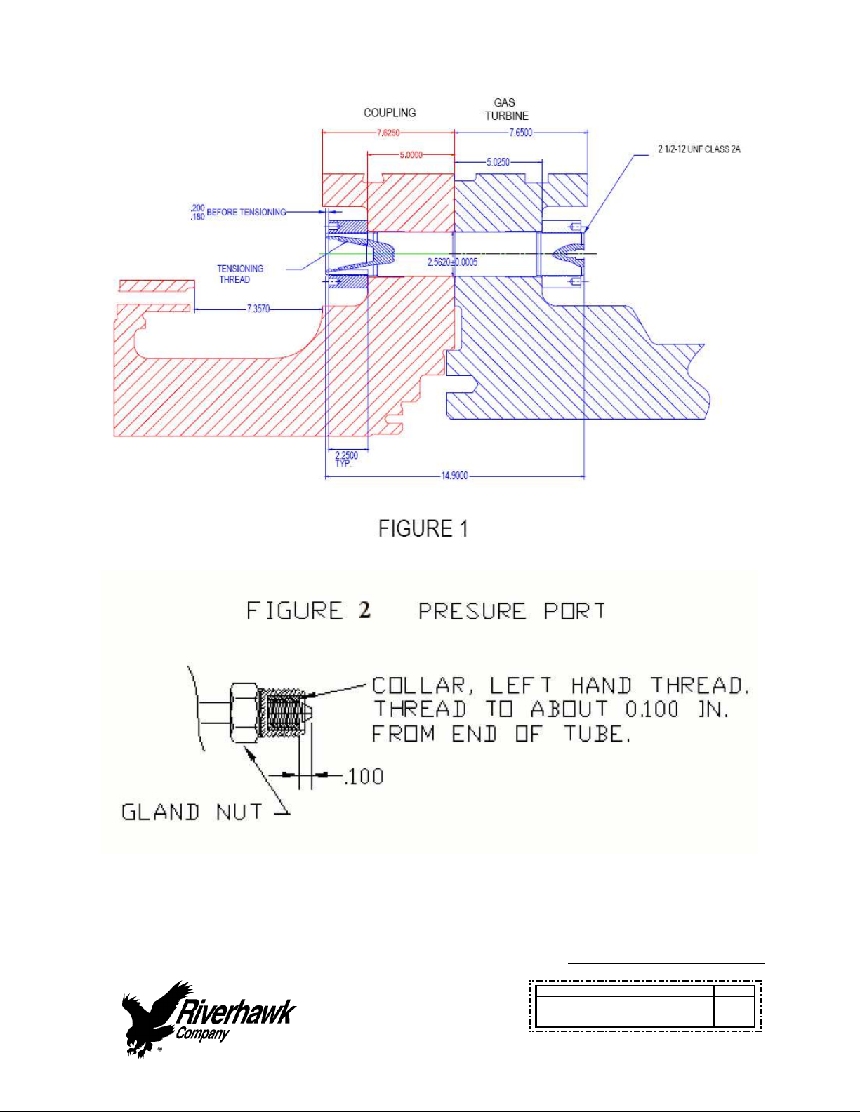
1. Refertothehardwareassemblydrawing(HF‐1730)listedinSection2.0ofthismanual.
Assemblethecylindricalnuttothetaperedthreadend(PullEnd)ofthestud.
2. SlidethestudandcylindricalnutassemblyintotheflangeasshowninFigure1and
installtheothernutonthebackside.
3. Adjustthenut/studassemblysothatthestudprotrudesfromthefaceofthecylindrical
nuttheamountdepictedonthehardwaredrawing(HF‐1730)0.180/0.200inches.
SETTINGTHISPROTRUSIONOFSTUDTONUTISCRITICALFORPROPERTENSIONER
OPERATION.
4. Hand‐tightentheassemblytoasnugfit.
7.0AssemblyofHydraulicTensionerEquipment
7.1KitAssembly
Assemblethehydraulicpumpwithitshosetothepullertoolandbleedthesystemofairper
followinginstructions.
Cleanpullerscrewandcheckforanydebrisanddents.
Pullerscrewshouldbefreetorotateandmovebackandforth.
Inspecttensionerguardforanysignsofdamage.Bentguardsshouldbereplaced.

InstructionManualIM‐139
CUSTOMER'SINFORMATIONBOX
CONTENTSAREINDEPENDENTOFRIVERHAWKDOCUMENTCONTROL
215ClintonRoad
NewHartford,NY13413
Tel:+13157684855
Fax:+13157684941
Email:[email protected]
REV
373A4004
GEDRAWINGNUMBER
RevisionE
Page11of23
7.1.1Fittings
Makesurebothmaleandfemalepartsarecleanandfreeofdebris;seeFigure2forfitting
configuration.Holdfemalepartsecurelywhentighteningsoastopreventdamagetothe
adjacenttubing.Ifthefittingleaksfirsttryretighteningasneeded.Ifleakingcontinuesthen
disassembleandcheckforscratchesordebrisontheseatingconicalsurfaces.Cleanas
required.Replaceplasticprotectivecapswhenfinishedwiththetooling.
7.2Pump
Pumpkitisshippedfullofhydraulicoil.Thepumpreservoircapissealedforshipment.Touse
turncaptotheventposition.Topreventoilspillageclosecapwhennotinuse,duringstorage
andshipment.LostoilshouldbereplacedwithEnerpacHydraulicOil.ISO32MineralOilmaybe
substituted,ifnecessary.
7.3BleedingHydraulicSystem
FollowthetensionerassemblyinstructionsofSection8.0.
TOAVOIDFAILURE,ENSURESAFETYANDPROPEROPERATIONTHETENSIONERASSEMBLY
MUSTBEMOUNTEDONTHESTUDBEFOREBLEEDINGTHESYSTEMANDTENSIONINGBEGINS.
1. MounttensioneronastudpertheassemblyinstructionsofSection8.0.
2. Makesurethepumpissituatedbelowthetensionerassembly.
3. Thetensionerassemblyhastwoports,oneforpressurizingandoneforbleedingthe
system.Theseportsserviceacommonchamberandthereforemaybetreated
interchangeability.Thebleedportmustalwaysbeorientedintheuppermostposition.
4. Thepullertoolisshippedwitha5/8in.[16mm]hexconedstembleederfitting
installed.Withthisfittingloosenedstrokethepumprepeatedlyuntilthestreamofoil
exitingthetoolisfreeofairthenretightenthefitting.
Note:Thehoseisstiff,useofthistoolingcanbesimplifiedbytemporarilymountingthepuller
toolononestudpriortofinaltighteningoffittings.Thiswillreducethetendencyforthe
fittingstoloosenduringuse.

InstructionManualIM‐139
CUSTOMER'SINFORMATIONBOX
CONTENTSAREINDEPENDENTOFRIVERHAWKDOCUMENTCONTROL
215ClintonRoad
NewHartford,NY13413
Tel:+13157684855
Fax:+13157684941
Email:[email protected]
REV
373A4004
GEDRAWINGNUMBER
RevisionE
Page12of23
8.0AssemblyofTensioneronStud
Alltensioning(pulling)willbeperformedfromthetaperedthreadendofthestudwith
orientationofthestudtotheflangeasshowninFigure1
8.1KitAssembly
Assemblethehydraulicpumpwithitshosetothetensionerandbleedout
8.1.1AssemblyofTensionerKitwithIntegralSafetyCage
RefertoTensionerAssemblydrawingandFigure3fortensionertoflangemounting.Assembly
sequenceisasfollows:
1. Openthehydraulicreturnvalveonthepumptoallowhydraulicfluidtobepushedback
fromthepullertoolintothepumpreservoirasthepullertoolistightened.(Thisis
automaticontheair‐operatedhydraulicpump)
2. Placethespannerringonthepullersidecylindricalnut.
3. Placeandholdthepullertoolovertheendtobetightened.
4. Applyalightcoatofcleanturbineoiloraspraylubricanttothepullerscrew.Donotuse
“NeverSeize”ontheconicalthreads.
5. Insertthepullerscrewthroughthepullertoolintothetaperedthreadofthestudandhand
tighten(EnsurethatthePullerNutdoesnotbottomonthePistonwheninstallingthe
PullerScrew,IfitdoesthenthePullerScrewmaynotbeFULLYSEATED)
6. Besurenottocross‐threadtheassembly
7. TightenthepullerscrewusingAllenwrenchesonthepullerscrewandthestud.
8. Installthepullernut(showninFigure3)untilitseatssnuglyonthepistonandcompresses
thepistontoit’soriginalposition(Thiswillcompressthepistoninthetensionerand
preventoverstrokingandsealdamage)andthenback‐off2flats.Thisisparticularly
importantforremovalbecausethestudshortensduringdisassemblyandthetensioner
maythenbind.
9. AtthispointtheTensionerAssemblyMUSTBEFREETOROTATE.Inotherwords,thepuller
screwistightinthestudandthepullernuthasbeenbacked‐offthe2flats.
Note:Ifthetoolisnotfreetorotateitismostlikelythatthenutsmustberepositionedsothat
thestudmaybeshiftedslightlytothepullertoolsideoftheflange.Thiscanbeaccomplishedas
follows:

InstructionManualIM‐139
CUSTOMER'SINFORMATIONBOX
CONTENTSAREINDEPENDENTOFRIVERHAWKDOCUMENTCONTROL
215ClintonRoad
NewHartford,NY13413
Tel:+13157684855
Fax:+13157684941
Email:[email protected]
REV
373A4004
GEDRAWINGNUMBER
RevisionE
Page13of23
1. Backoffthepullernutandslightlyloosenthepullerscrew.
2. Backoffthecylindricalnutoppositethepullertoolabout1/2turn.
3. Tightenthepullerscrewsidecylindricalnuttotakeuptheslack
4. Retightenthepullerscrewperaboveandcheckfortoollooseness
Note:Donotoverextendthestud.Overextensioncancausethepistontoloseitssealandleak
oil.
CAUTION
Personalinjuryandequipmentdamagecanoccurifthepullerscrewisnotsecurelyengaged
withthetaperedthreadsofthestud.Properengagementisachievedwhenthepullerscrewis
tightinthestudandthetensionerassemblyisfreetoturn.
9.0StudPullingandTensioning
Thestudswillbetensionedintwosteps,atapproximately50%pressureandatfinalpressure.
Followthetensioningsequenceforeachflangejointasdefinedonthedatasheetsfoundatthe
endofthismanual.
Note:Beforethreadingthepullerscrewintothestud,carefullycheckthecleanlinessofboth
thestud'sandthepullerscrew'sconicalthreads.Applyalightcoatofcleanturbineoilora
spraylubricanttothepullerscrew.Donotuse“NeverSeize”ontheconicalthreads.This
procedurewilleaseassemblyandassurepositivematingofthethreadsbeforetightening.
WARNING
ThesafetycageMUSTbeinplaceandhandskeptoutofdesignatedareasatalltimeswhenthe
pullertoolispressurizedotherwisepersonalinjurycanoccur.
9.1Tensioningat50%pressure
Afterthetensionerisproperlyinstalledapplyhydraulicpressuretothetool.Bringthepressure
tothe50%levelinaccordancewiththefollowingtable.
FlangePosition StudSize 50%Pressure 50%Stretch
TurbinetoCoupling 2.562"
[65.07mm]
7000psi
[480bar]
Donotmeasure
Donotuse

InstructionManualIM‐139
CUSTOMER'SINFORMATIONBOX
CONTENTSAREINDEPENDENTOFRIVERHAWKDOCUMENTCONTROL
215ClintonRoad
NewHartford,NY13413
Tel:+13157684855
Fax:+13157684941
Email:[email protected]
REV
373A4004
GEDRAWINGNUMBER
RevisionE
Page14of23
9.1.1TighteningofTurbinetoCouplingNuts
Tightenthecylindricalnutshand‐tightusingthepinwrenchandspannerring,asshownin
eitherFigure6orFigure7.Turnthenutuntilitbottomsontheflange.
9.2RemovingtheTensionerfromanInstalledStud
Thepullertoolremovalistobeaccomplishedasfollows:
1. Releasethepullertoolpressurebyopeningthevalveonthepump.Leavevalveopen.
(Thisisautomaticontheair‐operatedhydraulicpump)
2. Loosenthepullerscrewusinga3/8”hexkeywrench.
3. Tappingthewrenchwithahammermaybenecessarytoloosenthepullerscrew.
4. Unscrewthepullerscrewusinga3/8”hexkeywrench.
5. Movethetooltothenextstud/nutassemblytobetensioned,followingthe
sequence/patternasdefinedonthesupplieddatasheets
9.3TensioningatFinalPressure
Repeatthepullingandtighteningprocedurestatedaboveatfullpressure.Measuresthelength
ofthestudsafterallhavebeentensioned.Thefinalpressureandrequiredstretchvaluesare
listedinthefollowingtable
CAUTION
DONOTEXCEEDTHEMAXIMUMPRESSUREVIBROSCRIBEDONTHEPULLERBODY.Excessive
pressurecandamgethestudandpullerscrew.
FlangePosition StudSize FinalPressure FinalStretch
TurbinetoCoupling 2.562"
[65.07mm]
13500psi
[930bar]
0.026"‐0.029"
[0.66mm‐0.77mm]
FortheproceduresofeitherSections9.1or9.3excessivestretchvariationsorlowstretch
valuescanbecorrectedbyretensioningallorselectedstudstothepressurevaluesstatedin
theabovetable.Havefinalstretchvaluesapprovedbythesupervisorresponsibleforthe
installation

InstructionManualIM‐139
CUSTOMER'SINFORMATIONBOX
CONTENTSAREINDEPENDENTOFRIVERHAWKDOCUMENTCONTROL
215ClintonRoad
NewHartford,NY13413
Tel:+13157684855
Fax:+13157684941
Email:[email protected]
REV
373A4004
GEDRAWINGNUMBER
RevisionE
Page15of23
10.0ThreadLocking
Mechanicallocknutshavetwosetscrewslocatedinthetopface,seeFigure4.Before
threadingthenutontothestudchecktobecertainthesetscrewsarefreetoturn.Oncethe
nutisseatedtorquethesetscrewstothevaluesspecifiedinthefollowingtable.Whenseated
andtorquedtothevaluesspecifiedtheloadcreatedbythesetscrewdisplacesthethreadof
thenutintheareaofthewebcreatingthedesiredlockingaction
StudSize SetScrewSize Torque
2.562"
[65.07mm] 1/4"‐28UN 100in∙lbs‐110in∙lbs
[11.3N∙m–12.4N∙m]
11.0Stud/NutRemoval
Forthoseassembliesthathavebeenlockedusingmechanicallocknuts,removalis
accomplishedasfollows:
1. Usingawirebrushandshopaircleantheinternaltaperedthreadofthestudtoremoveany
debris/depositswhichmayhaveaccumulatedduringservice.(seesection5.2.1)
2. WithanAllen‐wrenchloosenthetwolockingsetscrewsbutdonotremovefromnutsee
Figure4.
3. InstalltheappropriatepullertooltothestudasdescribedinSection8.0.
4. ApplytheappropriatehydraulicpressureperthetableofSection9.3andusingthespanner
ringandspannerwrenchesshowninFigure3loosenthenut,thenreleasethepressureand
removethepullertool
12.0FrequentlyAskedQuestions
Thissectioncontainssomefrequentlyaskedquestionsandproblems.Ifthestepslistedheredo
notsolveyourproblem,contacttheRiverhawkCompanythruourwebsite,email,orphonecall.
Q: Atensionerhaspulleditselfoutofthestud'sconicalthreads.CanIcontinueusinga
tensioneronthisstud?

InstructionManualIM‐139
CUSTOMER'SINFORMATIONBOX
CONTENTSAREINDEPENDENTOFRIVERHAWKDOCUMENTCONTROL
215ClintonRoad
NewHartford,NY13413
Tel:+13157684855
Fax:+13157684941
Email:[email protected]
REV
373A4004
GEDRAWINGNUMBER
RevisionE
Page16of23
A: No.Boththetensionerandthestudmayhavebeendamaged.Ifthestudistensioned,a
NutBusterrepairkit,fromRiverhawk,mustbeusedtoremovethedamagedstudby
drillingoutthenut.Riverhawkcansupplyareplacementstudandnutbasedonthe
initialweightcertificationsuppliedwiththehardwareset(seesection4.2).The
damagedtensionershouldalsobereturnedtoRiverhawkforinspectionandrepair.
Q: Thehydraulictensionerhasbeentakenuptoitsfinalpressure.Thefinalstretchlength
isshortofthefinalstretchtarget.Whatisthenextstep?
A: Donotincreasethehydraulicpressure.Checkifthehydraulicpumpissettotheright
pressure.Installthetensionerandre‐pressurizethetensionertothefinalpressurethen
recheckthestretchmeasurement.Ifthestretchvalueisstillshort,removethestud
fromtheholeandre‐measurethestud'sinitiallengththentrytoinstallthestudagain.
Q: Thehydraulictensionerhasbeentakenuptoitsfinalpressure.Thefinalstretchlength
islargerthanthefinalstretchtarget.Whatisthenextstep?
A: Removethestudfromthebolthole.Checkifthehydraulicpumpissettotheright
pressure.Re‐measurethestud'sinitiallengththentrytoinstallthestudagain.
Q: Isthereaneasierwaytosupportormovethetensioneraroundthecouplingshaft?
A: Usetwostraps.Onearoundthecouplingshaftandtheotherattachtoanyoverhead
support.Strapsmustbeslackduringmountingtensionertostudandduringtensioning.
Q: Thetensionerisatitsfinalpressure,butthenutcannotbeloosen.
A: Ifthenutscannotbeloosenedatthefinalpressure,continuallyincreasingthepressure
willnothelpandcanbedangerousandinsomecasesmakeithardertoremovethenut.
Checkthenuttoseeifitssetscrewshavebeenloosened.Checkforandremoveany
corrosionaroundthenut'sthreads.
Q: HowdoIcleantheconicalthreadsonastud?
A: Theconicalthreadsarebestcleanedusingaspiralwound brassbrushinadrillas
describedinsection5.2.1
InstructionManualIM‐139
CUSTOMER'SINFORMATIONBOX
CONTENTSAREINDEPENDENTOFRIVERHAWKDOCUMENTCONTROL
215ClintonRoad
NewHartford,NY13413
Tel:+13157684855
Fax:+13157684941
Email:[email protected]
REV
373A4004
GEDRAWINGNUMBER
RevisionE
Page17of23
Q: Duringtheinitialstepsofremovingatensionedstud,thestick‐outlengthisfoundtobe
wrong.
A: Donotproceed.ContactRiverhawkforassistance.Withthewrongstick‐outlength,the
hydraulictensionerhasalimitedstrokeandmaynotworkproperlyandcanbe
damaged.
Q: Thehydraulicpumpappearstobeleaking.
A: Checkthehoseconnectiontothehydraulicpump.Ifthe1/4"highpressurefittingisnot
assembled,itmaylooklikethepumpisleaking.Iftheproblemcontinues,itmaybe
necessarytoopenthepumpkit.ContactRiverhawkforguidance.
Q: Thehydraulichosehasacollaronitthatcan'tbemovedbyhand
A: Thecollarissometimesheldinplacewithathreadlockingcompound.Thispreventsthe
collarfrommovingtooeasily.Itmaybenecessarytoadjustthiscollarwithasetofvise‐
grippliers.Becarefultonotstripthethreadsoffthetubeorhoseend.
13.0RevisionHistory
Revision
Letter
EffectiveDate Description
E May18,2022 UpdatedECDeclarationofConformity;AddedUKCA
DeclarationofConformity
D Jan15,2015 UpdatedSection1.0,4.3and15.0.
C Jun13,2014 AddedECDeclarationofConformity
B Jun10,2009 Addedturbineoilandremoved“NeverSeize”from
sections1.0,3.0,8.1.1,and9.0
A Mar25,2009 Addedsections3and12
InstructionManualIM‐139
CUSTOMER'SINFORMATIONBOX
CONTENTSAREINDEPENDENTOFRIVERHAWKDOCUMENTCONTROL
215ClintonRoad
NewHartford,NY13413
Tel:+13157684855
Fax:+13157684941
Email:[email protected]
REV
373A4004
GEDRAWINGNUMBER
RevisionE
Page18of23
‐ Dec17,2001 Released
AppendixA1
ECDeclarationofConformity
Manufacturer: RiverhawkCompany
Address: 215ClintonRoad
NewHartford,NY13413,USA
Thehydraulicpumpandbolttensioningtooldescribedinthismanualareusedforinstallingand
applyingtensiontolargeboltsthatarespecificallydesignedbyRiverhawkCompanytobe
tensionedhydraulically.
AllapplicablesectionsofEuropeanDirective2006/42/ECformachineryhavebeenappliedand
fulfilledinthedesignandmanufactureofthehydraulicpumpandbolttensioningtool
describedinthismanual.ReferencealsoISO12100:2010,ISO4413:2010,andISO4414:2010.
Furthermore,thisequipmenthasbeenmanufacturedundertheRiverhawkqualitysystemper
ENISO9001:2015
ConsulttheDeclarationofConformanceincludedwiththeshipmentofthisequipmentthat
identifiestheauthorizedRiverhawkrepresentative,applicableserialnumbers,andappropriate
signature.

InstructionManualIM‐139
CUSTOMER'SINFORMATIONBOX
CONTENTSAREINDEPENDENTOFRIVERHAWKDOCUMENTCONTROL
215ClintonRoad
NewHartford,NY13413
Tel:+13157684855
Fax:+13157684941
Email:[email protected]
REV
373A4004
GEDRAWINGNUMBER
RevisionE
Page19of23
AppendixA2
UKCADeclarationofConformity
Manufacturer: RiverhawkCompany
Address: 215ClintonRoad
NewHartford,NY13413,USA
Thehydraulicpumpandbolttensioningtooldescribedinthismanualareusedforinstallingand
applyingtensiontolargeboltsthatarespecificallydesignedbyRiverhawkCompanytobe
tensionedhydraulically.
AllapplicablesectionsofSupplyofMachinery(Safety)2008havebeenappliedandfulfilledin
thedesignandmanufactureofthehydraulicpumpandbolttensioningtooldescribedinthis
manual.ReferencealsoISO12100:2010,ISO4413:2010,andISO4414:2010.
Furthermore,thisequipmenthasbeenmanufacturedundertheRiverhawkqualitysystemper
ENISO9001:2015
ConsulttheDeclarationofConformanceincludedwiththeshipmentofthisequipmentthat
identifiestheauthorizedRiverhawkrepresentative,applicableserialnumbers,andappropriate
signature.
InstructionManualIM‐139
CUSTOMER'SINFORMATIONBOX
CONTENTSAREINDEPENDENTOFRIVERHAWKDOCUMENTCONTROL
215ClintonRoad
NewHartford,NY13413
Tel:+13157684855
Fax:+13157684941
Email:[email protected]
REV
373A4004
GEDRAWINGNUMBER
RevisionE
Page20of23
Table of contents
Other riverhawk Industrial Equipment manuals

riverhawk
riverhawk IM-116 User manual

riverhawk
riverhawk IM-477 User manual

riverhawk
riverhawk IM-125 User manual

riverhawk
riverhawk IM-186 User manual

riverhawk
riverhawk IM-278 User manual

riverhawk
riverhawk IM-150 User manual

riverhawk
riverhawk IM-255 User manual

riverhawk
riverhawk IM-269 User manual

riverhawk
riverhawk IM-164 User manual

riverhawk
riverhawk IM-257 User manual


