manuals.online logo
Brands
  1. Home
  2. •
  3. Brands
  4. •
  5. Robinsons
  6. •
  7. Greenhouse Kit
  8. •
  9. Robinsons 8 DWARF Lean-To User manual

Robinsons 8 DWARF Lean-To User manual

NOMINAL SIZE A (mm) B (mm)
8lt x 6
2549
1990
8lt x 8 2610
8lt x 10 3230
8lt x 12 3850
NOMINAL SIZE A (mm) B (mm)
6ft extension - 1860
2
Thank you for purchasing your new Robinsons greenhouse. We recommend you familiarise yourself with the instructions and read all safety
information before you commence assembly. This instruction manual is also available online at www.robinsonsgreenhouses.co.uk
in our technical help section should you need to reprint it. Should you require any additional advice you can always call us on 01782 385409.
These instructions are divided into sections highlighted by a white number/letter on a black background at the bottom corner of most pages (see opposite
page for details); part lists, B-base, P-preparation, 1-side, 2-front gable, 3-rear, 4-joining the three sides together, 5-roof, 6-wall attachment, 7-vent, 8-
door, 9-glazing, 10-vent attachment, 11-door attachment, 12-anchoring down, 13-optional louvre, 14-optional shelf, 15-optional staging, 16-finishing
touches, Door/s on side of structure rather than or in addition to the gable/s. If you need to contact us for assistance please refer to the relevant section/
s. If your building is longer than 12’, i.e. has an extension then please also refer the separate extension manual.
Safety Warning
 Glass and aluminium can potentially cause injury. Please ensure you wear protective goggles, gloves, headgear and suitable footwear when
assembling and glazing the building.
 Please remember that glass is fragile and should be handled with extreme care. Always clear up and dispose of any breakages immediately.
 Do not assemble the greenhouse in high winds.
 For safety reasons and ease of assembly, we recommend that this greenhouse is assembled by a minimum of two people.
 Please clear all lying snow from the greenhouse roof as it can cause the roof to buckle or collapse.
Site Preparation
 When selecting a site for your greenhouse, it is vital that you choose as flat and level an area as possible.
 A concrete or slabbed base will provide the most solid foundation for your greenhouse.
 IMPORTANT: Do not fix your building down until the building is fully assembled, including glazing.
 Avoid placing your greenhouse under trees or in other vulnerable locations.
 To minimise the risk of wind damage, try to select as sheltered a site as possible, e.g. beside a hedgerow or garden fence.
Additional Considerations
 Please bear in mind that assembling your greenhouse can be time consuming. You may need to spread the construction over two or more
days. We recommend that you avoid leaving the building partially glazed. If you ever have to leave your greenhouse half assembled and not
anchored down, weigh it down with slabs or bags of sand to stop the wind moving it.
 You will find it helpful to prepare a large, clean and clear area in which to work in. A garage floor or flat lawn area is ideal.
 If you have arranged for someone to install your greenhouse for you, please check that all components are included. The components can be
identified by their distinctive profiles, lengths and quantities detailed in the parts list (see next page).
 Anchoring down your greenhouse should be the final stage of construction (including glazing).
 Once installed your greenhouse requires little maintenance, but to maintain the smooth running of
your door(s) WD40 or similar can be applied to the door wheels and lower door guides.
Guarantee
 Your new Robinsons greenhouse is guaranteed for 10 years against faulty manufacture of the frame-
work. This does not include glazing, moving parts, accidental damage or wind damage.
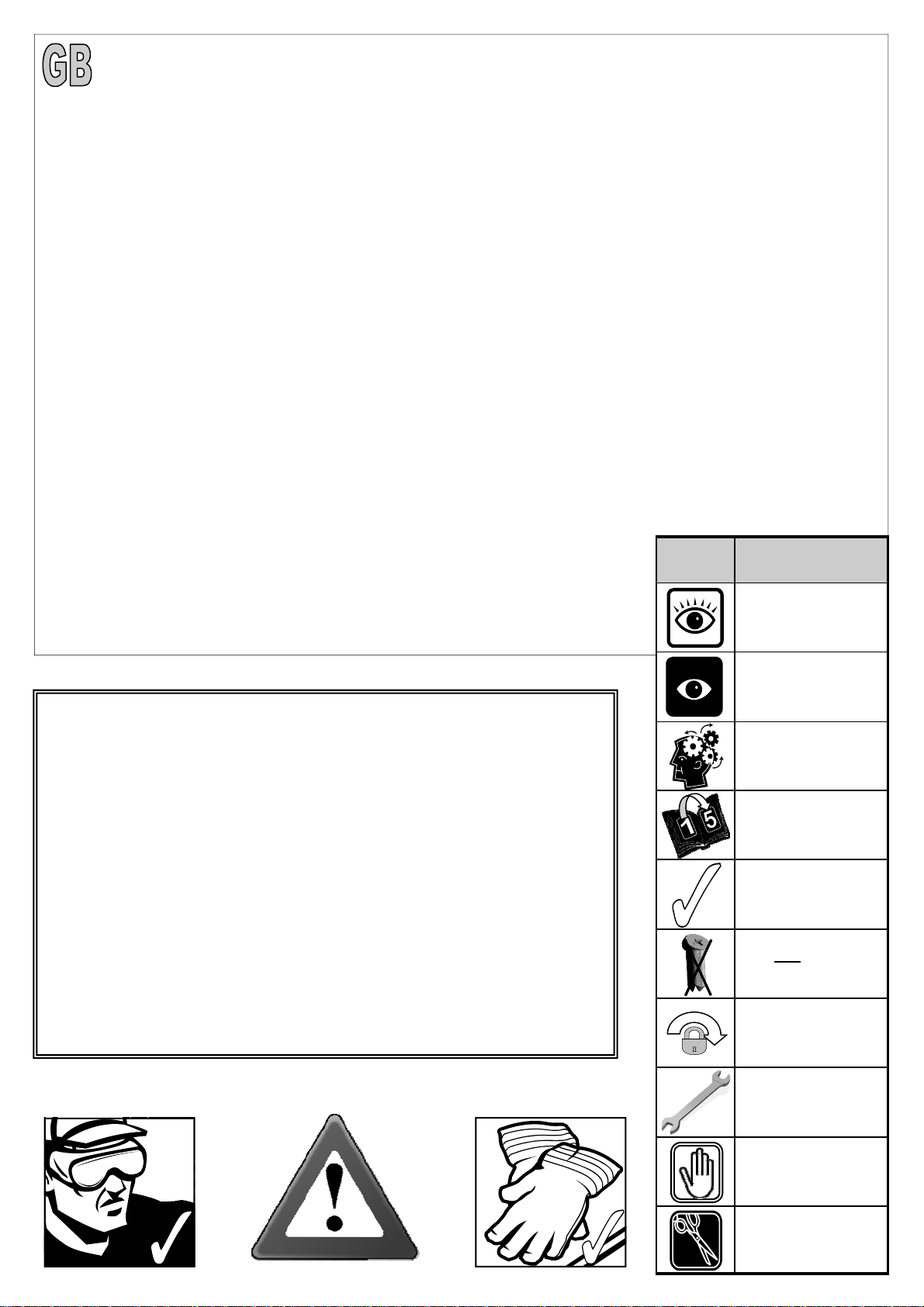
KEY
SYMBOL KEY DESCRIPTION
EXTERNAL VIEW
THINK
THIS SECTION
RELATES TO
ANOTHER
(e.g. 1 to 5)
CORRECT
DO NOT FIX DOWN!
TWIST TO LOCK
TIGHTEN
PUSH AND HOLD
CUT TO LENGTH
INTERNAL VIEW
UPDATE: Robinsons plastic / aluminium cover strips -
On a Robinsons building the glazing capping is in two parts. The lower plastic
capping screws into the glazing bars pressing the glass down onto its rubber
beading. The upper plastic / aluminium covers then need to be applied to cover
the heads of the self-tapping screws. If you are struggling to press on the cover
strips then we recommend the use of a rubber mallet or perhaps a wooden block
and hammer, a short sharp tap onto the cover at one end is all that is needed to
stretch the cover around the lower capping protrusions locking it into place. You
can then either continue to use the mallet along the length of the cover or con-
tinue just using the palm of your hand. Once in the building and the edges are
protected Robinsons 4mm thick toughened safety glass is very strong and can
cope with the vibrations caused by hitting the covers though we would not rec-
ommend that you hit the glass directly. Some of the aluminium cover caps have a
hole in them at one end which is sometimes used to hang the parts for powder
coating. You can if you wish use the hole to stop the covers from sliding in the
roof using a glazing screw, note you will have to use a countersunk screw under
the vents to avoid interference with the vent bottom.
3
SECTION
No TITLE ASSEMBLY SYNOPSIS: IMPORTANT INFORMATION / CONSIDERATIONS
PARTS LIST Identify and separate all like for like components prior to assembly. The ‘parts list’ also separates parts
into the various sections 1 - 12 shown below. Parts can also be identified by their profile pictures and
stated lengths etc..
B
BASE Base dimensions and recommendations. Ensure that your base is level as this will make assembly of
the building, especially the glazing of the roof much more straight forward.
P PREPARATION Tools required. IMPORTANT: Use WD40 or similar in the glazing bar channels and insert the black glaz-
ing rubber prior to frame assembly.
1
SIDE Take the side glazing bars ‘D609’ with the rubber inserted and the diagonal braces ‘D604’, use 10mm
bolts to join them to the gutter and 15mm bolts to the cills (note how the head of the bolt slides into each
glazing bar during construction).
2 FRONT Again ensuring that the gable framework is rubbered-up follow the diagrams to assemble each end of
the building. Make sure that you have inserted the extra bolts utilised in sections 4, 5 and 11. On the
roof and side corner bars not every rubber channel will require rubber unless it is to be utilised in a parti-
tion (see separate manual and section P).
3 REAR
4 JOINING THE
THREE SIDES Take the side (1) and both gables (2 & 3) and join them together on your base. It is a good idea to tie
some ladders to the side to support them if you do not have anyone to hold them for you.
5 ROOF Attach the ridge and then the rubbered-up roof bars ensuring that they are fully butted up to the ridge
and down onto the gutter. In order to make fitting the roof purling (D593-596) easier slide one 10mm bolt
into each roof bar, they are less fiddly than using the twist in crop heads. Some tubular braces are sup-
plied to add extra strength, they can be fitted now or later with crop head bolts.
7a VENT Once the vent is glazed add silicone to the vent sides and top. Stand the vent/s on their hinge (vent top)
and then leave the silicone to set.
7b VENT SLAM The slam bar ‘D079’ can be moved up and down between the roof glazing bars so that it can be butted
down onto the pane of glass beneath, the autovent will be attached to it later on (10).
8 DOOR/S Construct the door using the diagrams and then leave to one side ready for attachment in section (11).
9
GLAZING
Layout the bar cappings and covers around the building like a sundial checking that all is present and
correct. You can also place the roof cappings in the gutters so they are closer to hand. You will notice
that your roof cappings (D924 / D929) are in one long section however you can cut this into two sections
if you wish due to the glass overlap in the roof. This will remove the bulge in the roof capping, however
keep the roof cover strips (D928) full lengths for the neatest finish.
The glass in the ends has to bevel on the black separator strip, this bevelling action allows the glass to
tuck underneath the roof corner canopy. Use the capping and the self tapping screws to then hold the
glass in place. The covers then enclose the screw heads giving a neat finish.
10 VENT
ATTACHMENT Take the assembled vent and slide the vent hinge ‘D866’ into the end of the ridge allowing the vent to
pivot open and closed. Vent stops go either side of the vent to stop any lateral movement (so insert
stop / vent / stop). Attachment of the Bayliss XL autovents.
11 DOOR
ATTACHMENT Use the bolts inserted in section (2) to attach the upper door track. The lower door runner ’D861’ and
ramp threshold ‘D088’ push down and lock together.
12 ANCHORING
DOWN Now that the greenhouse is finished and the door and vent/s are operating without interference then you
need to anchor the building down using 2” rawl plugs and screws. Use a 7mm masonry bit in a hammer
drill to create the holes.
13 OPTIONAL
LOUVRE They attach to the building during the glazing process (9) like a piece of glass with a black separator
above and below them.
14
OPTIONAL
SHELVING
15
OPTIONAL
STAGING
16 FINISHING
TOUCHES Now that the main body of the structure is complete you can add; downpipe fittings, eave bungs.
Robinsons integral cantilever staging and shelving attaches to the inside of the greenhouse frame using
either square head bolts (insert four into each side glazing bar ’D609’ during construction of the sides
(1)) or rectangular ‘crop head’ bolts which can be fitted retrospectively (both sets of bolts accompany the
shelving/staging). This system allows the height of either the staging or the shelf to be set at an operator
specific height. Commonly the staging brackets are set 900mm from the cills though you can alter this to
suit the end user/s. The aluminium shelf / staging slats come in two lengths; (4’):1240mm ‘D2002’ and
(6’):1860mm ’D2003’. These slats can combine to create any length of staging required, i.e. 4’+6’ = 10’
etc...
6 REAR WALL
ATTACHMENT The main body of the frame is complete it can be attached to the wall. Make sure that the wall bars are
vertical and the ridge is horizontal then drill and screw the building to the wall. Do not attach the base to
the ground until section (12) as your building may not be square.
4
Section
Ref Part
No. Section Size
(mm) 8lt
6 8lt
8 8lt
10 8lt
12 Section
Ref Part
No. Section Size
(mm) 8lt
6 8lt
8 8lt
10 8lt
12
D043 1894 1
D021 2514 1
D022 3134 1
D023 3754 1
D975 1897 1
D974 2517 1
D979 3137 1
D978 3757 1
D604 1316 2
D609
1160
2
3
4 .
5
RUBBER 1000
(1m)
5
7
10
12
D174
N/A
2
2
4
4
D976 1897 1
D973 2517 1
D981 3137 1
D977 3757 1
D593 1897 1
D594 2517 1
D595 3137 1
D596 3757 1
D927
2545
2
3
4
5
RUBBER 1000
(1m)
11
16
21
26
D866
639
1
1
2
2
D863L
613
1
1
2
2
D863R
613
1
1
2
2
D862
593
1
1
2
2
D079
PLUS FLUFF
590
1
1
2
2
D114
N/A
2
2
4
4
D220
PLUS
FS6060
SCREW
N/A
2
2
4
4
D205
N/A
2
2
4
4
D037
2510
1
D600
1270
1
D605(R) 690
1?
D606(L) 690
D632L 650
1?
D632R 650
D604 1316 2
D608
1160
2
D955
2037
1
D957
2257
1
D985
1487
1
D992
1267
1
D993
1377
1
D997
1590
2
D113
2510
1
D925
2545
2
RUBBER 1000
(1m)
34
D174
N/A
9
5
Section
Ref Part
No. Section Size
(mm) 8lt
6 8lt
8 8lt
10 8lt
12
10mm
22
25
28
15mm
39
40
41
m6
61
65
69
19
38
57
MAIN FRAME QUANTITIES
VENTS / DOORS etc SEPERATE
D090 +
D347 lock =
D301
1824
1
D092 +
D156 strike =
D303
1824
1
D093
1824
1
D094
1824
1
D096 +
D217 wheel =
D307
611
2
D095
611
2
D097
611
2
D232 905 4
D233 797 4
P053
N/A
2
D225
610
2
D840B
4000
1
D861
2450
D088
1207
1
D086
2510
1
D085
2510
1
D153 198 2
1
D163 90 2
D150 N/A 1
D154 N/A 2
D865
1210
1
D930
246
1
Section
Ref Part
No. Section Size
(mm) 8lt
6 8lt
8 8lt
10 8lt
12
1 D618 1144 2 3 4 5
2 D821 366 1
5 D929 2553 2 3 4 5
2 D969 140 1
3 D987 1370 1
3 D991 1260 1
3 D986 1480 1
2/3 D999 1590 2
2 D819 227 1
1 D620 1144 2
2 D814 1883 2
5 D924 2553 2
2/3 D610 1160 2
2/3 D614 1162
1 D619 1144 4 5 6 7
2 D831 368 1
2 D836 1883 2
2 D846 229 1
5 D928 2553 4 5 6 7
2 D970 140 1
3 D988 1370 1
3 D989 1480 1
3 D990 1260 1
2/3 D998 1590 2
2
6
7
PARTITION
ONLY
REFER TO
SEPARATE
MANUAL
Feed glazing rubber into each glazing bar and
trim to length. Notice that some channels are
only used on a partition. Applying a lubricant to
the aluminium channels will speed up insertion.
The frame is assembled by feeding square
headed bolts, either 10mm or 15mm in length
into the slots on glazing bars and then locating
those bolts through holes in purlings and cills,
etc… Twist in (rectangular) crop headed bolts
are also used towards the end of construction
to attach components to the frame when the
glazing bar slots are no longer exposed at the
ends. 10mm
15mm
PARTITION
ONLY
REFER TO
SEPARATE
MANUAL
8
6
X 1
12
X 1
8
X 1
10
X 1
D975
D043
D974
D021
D979
D022
D978
D023
Part No mm Quantity
D978 3757 1
D023 3754 1
D609 1160 5
D604 1316 2
D174 4
M6-
10mm 5
M6-
15mm 7
M6-
NUT 12
12 X 1 DWARF
Rubber 1000 12
Part No mm Quantity
D979 3137 1
D022 3134 1
D609 1160 4
D604 1316 2
D174 4
M6-
10mm 4
M6-
15mm 6
M6-
NUT 10
10 X 1 DWARF
Rubber 1000 10
Part No mm Quantity
D974 2517 1
D021 2514 1
D609 1160 3
D604 1316 2
D174 2
M6-
10mm 3
M6-
15mm 5
M6-
NUT 8
8 X 1 DWARF
Rubber 1000 7
Part No mm Quantity
D975 1897 1
D043 1894 1
D609 1160 2
D604 1316 2
D174 2
M6-
10mm 2
M6-
15mm 4
M6-
NUT 6
6 X 1 DWARF
Rubber 1000 5
+
9
D604
TRANSIT
BOLT ON
DIAGONALS
15mm
D604
15mm
D609
10mm
D609
10
D955
Part No mm Quantity
D600 1270 1
D604 1316 1
D605(R) 690 1
D608 1160 1
D632L 650 1
D925 2545 1
D955 2037 1
D957 2257 1
D997 1590 1
D600
D632L D632R
D608 D608
D925 D925
Part No mm Quantity
D174 4
D227 17m
M6X10 5
M6X15 11
M6NUT 16
D957
D600
D997 D997
Part No mm Quantity
D600 1270 1
D604 1316 1
D606(L) 690 1
D608 1160 1
D632R 650 1
D925 2545 1
D955 2037 1
D957 2257 1
D997 1590 1
DOORS ON
LEFT
EXTERNAL
VIEW
DOORS ON
RIGHT
EXTERNAL
VIEW
D605(R) D606(L)
D957 D955
10mm
10mm
10mm
10mm
15mm
15mm
15mm
15mm
10mm
15mm
15mm
10mm
15mm
15mm
15mm 15mm
10mm
15mm
15mm
15mm
10mm
15mm
15mm
15mm
10mm
15mm
10mm
15mm
DOORS ON LEFT DOORS ON RIGHT
+
D604 D604
11
D955
D605(R) /
D606(L)
D174
D608
D605(R) /
D606(L)
D600
D608
D925 D925
D955 /
D957
D604
D997
D925
D955 /
D957
12
D985
D997 D608
D925
D037 D037
D925
Part No mm Quantity
D174 5
D227 17m
M6X10 6
M6X15 12
M6NUT 18
Part No mm Quantity
D037 2510 1
D113 2510 1
D604 1316 1
D608 1160 1
D925 2545 1
D985 1487 1
D992 1267 1
D993 1377 1
D997 1590 1
DOORS ON
LEFT
EXTERNAL
VIEW
DOORS ON
RIGHT
EXTERNAL
VIEW
Part No mm Quantity
D037 2510 1
D113 2510 1
D604 1316 1
D608 1160 1
D925 2545 1
D985 1487 1
D992 1267 1
D993 1377 1
D997 1590 1
D113 D113
D993 D992
D608 D985
D993
15mm
15mm
15mm
15mm
10mm
15mm
15mm
10mm
15mm
15mm
10mm
15mm
15mm
10mm
15mm
15mm
10mm
10mm
10mm
10mm
D992
D604 D604
D997
13
D608
D113
D997
D037
D037
D037
D997
D925
D925
D993 /
D985
D608
D925
D113
D604
14
EQUAL
15
1
2
2
D927
1
2
X2
2
D927
D609
6’
Part No mm Quantity
D976 1897 1
D927 2545 2
RUBBER 1000 11
D593 1897 1
4 8’
Part No mm Quantity
D973 2517 1
D927 2545 3
RUBBER 1000 16
D594 2517 1
6 10’
Part No mm Quantity
D981 3137 1
D927 2545 4
RUBBER 1000 21
D595 3137 1
8 12’
Part No mm Quantity
D977 3757 1
D927 2545 5
RUBBER 1000 26
D596 3757 1
10
1
D126
1
16
D234
EQUAL
D234
17
8x6 8x8 8x10 8x12
Part No mm Quantity
SYSCR3 75 9 10 11 12
SYRAWL 50 9 10 11 12
7mm
No 10 x 3”
D119
SILICONE
There are various methods for attaching your greenhouse frame to its wall.
1) Drill through the vertical wall bars with a 7mm drill/hammer drill using a 7mm masonry bit, Use 3”
screws to secure the wall bars.
2) Drill through the vertical wall bars with a 7mm drill bit and enlarge the inner hole to 10mm. Use 2“
screws to secure the wall bars hiding the screw heads inside the bars to give a neat finish.
3) Use L-shaped brackets and 2” screws to secure the frame to the wall similar to anchoring the green-
house down (e.g. section 12).
18
D1208
1 of -
610 x 610
pane
D866
D863R
D863L
D866
639
1
D863L
613
1
D863R
613
1
D862
593
1
Part No mm Quantity
D220
PLUS
FS6060 SCREW
N/A 2
D205
N/A
2
SY-
BOLM6X11 10 4
SYNUTM6 M6 4
8 X 12 S/T
FS6017 10 2
Part No mm Quantity
8 x 19 S/T
FS6018 19 2
D863R
D866
2
2
D1208
1 of -
610 x 610
pane
19
D862 D862
D863L
2
2
2
2
2
FLIP
VIEW
D119
CUT
6mm
SILICONE
20
D114
D079
FLIP
VIEW
D079
PLUS
FLUFF
590
1
D114 N/A 2
Part No mm Quantity
SY-
BOLM6X11 10 2
SY-
BOLM6X15 15 2
SYBOLM6
X11CROP 10 2
SYNUTM6 N/A 4
Part No mm Quantity
D114

Other Robinsons Greenhouse Kit manuals

Robinsons Rosette DWARF User manual

Robinsons

Robinsons Rosette DWARF User manual

Robinsons 5ft Wide LEAN-TO User manual

Robinsons

Robinsons 5ft Wide LEAN-TO User manual

Robinsons Victorian RUSHMOOR 8 Dwarf User manual

Robinsons

Robinsons Victorian RUSHMOOR 8 Dwarf User manual

Robinsons Regal User manual

Robinsons

Robinsons Regal User manual

Robinsons Lean-To 5 User manual

Robinsons

Robinsons Lean-To 5 User manual

Robinsons Extensions 6ft User manual

Robinsons

Robinsons Extensions 6ft User manual

Robinsons Royale User manual

Robinsons

Robinsons Royale User manual

Robinsons Victoria Partition User manual

Robinsons

Robinsons Victoria Partition User manual

Robinsons 4' Lean-To User manual

Robinsons

Robinsons 4' Lean-To User manual

Robinsons Roemoor 15 User manual

Robinsons

Robinsons Roemoor 15 User manual

Robinsons Renown User manual

Robinsons

Robinsons Renown User manual

Robinsons Victorian RUGBY 6 Dwarf User manual

Robinsons

Robinsons Victorian RUGBY 6 Dwarf User manual

Robinsons ROYDON Victorian 10 3/4 SPAN. Dwarf User manual

Robinsons

Robinsons ROYDON Victorian 10 3/4 SPAN. Dwarf User manual

Robinsons Renown Dwarf User manual

Robinsons

Robinsons Renown Dwarf User manual

Robinsons Rowton User manual

Robinsons

Robinsons Rowton User manual

Robinsons 6' Lean-To User manual

Robinsons

Robinsons 6' Lean-To User manual

Robinsons Regent User manual

Robinsons

Robinsons Regent User manual

Robinsons Victorian 13 ROLLESTON 3/4 SPAN Porch Dwarf User manual

Robinsons

Robinsons Victorian 13 ROLLESTON 3/4 SPAN Porch Dwarf User manual

Robinsons Regatta DWARF User manual

Robinsons

Robinsons Regatta DWARF User manual

Robinsons Radley Series User manual

Robinsons

Robinsons Radley Series User manual

Robinsons Reach REGAL User manual

Robinsons

Robinsons Reach REGAL User manual

Robinsons Victorian ROOKLEY 14 Series User manual

Robinsons

Robinsons Victorian ROOKLEY 14 Series User manual

Robinsons Rosette User manual

Robinsons

Robinsons Rosette User manual

Robinsons Royale DWARF User manual

Robinsons

Robinsons Royale DWARF User manual

Popular Greenhouse Kit manuals by other brands

ACF Greenhouses SOLAR HARVEST SH7 Assembly instructions

ACF Greenhouses

ACF Greenhouses SOLAR HARVEST SH7 Assembly instructions

Vitavia Calypso 3000 Assembly instructions

Vitavia

Vitavia Calypso 3000 Assembly instructions

Holman GH1001 instruction manual

Holman

Holman GH1001 instruction manual

Flower House PlantHouse 2 Setup instructions

Flower House

Flower House PlantHouse 2 Setup instructions

ACF Greenhouses SOLAR HARVEST SH7 Assembly instructions

ACF Greenhouses

ACF Greenhouses SOLAR HARVEST SH7 Assembly instructions

ClearSpan PB00556R3S manual

ClearSpan

ClearSpan PB00556R3S manual

Palram Snap&Grow Assembly instructions

Palram

Palram Snap&Grow Assembly instructions

Dancover GH152190 Assembly instructions

Dancover

Dancover GH152190 Assembly instructions

Sproutwell Small Circle Assembly instructions

Sproutwell

Sproutwell Small Circle Assembly instructions

Vitavia VM0035-P Assembly instructions

Vitavia

Vitavia VM0035-P Assembly instructions

Palram CANOPIA AMERICANA 12x12/3.7x3.7 How to assemble

Palram

Palram CANOPIA AMERICANA 12x12/3.7x3.7 How to assemble

Palram CANOPIA SANREMO 3x3 How to assemble

Palram

Palram CANOPIA SANREMO 3x3 How to assemble

TMG TMG-GH1030R product manual

TMG

TMG TMG-GH1030R product manual

FRAME IT ALL Alamo 8x8 manual

FRAME IT ALL

FRAME IT ALL Alamo 8x8 manual

Hercules Bosworth LEAN-TO manual

Hercules

Hercules Bosworth LEAN-TO manual

Dancover GH158011 manual

Dancover

Dancover GH158011 manual

GrowSpan PGFLSAXXFCW0063 manual

GrowSpan

GrowSpan PGFLSAXXFCW0063 manual

HOKLARTHERM Riga Mounting instruction

HOKLARTHERM

HOKLARTHERM Riga Mounting instruction

manuals.online logo
manuals.online logoBrands
  • About & Mission
  • Contact us
  • Privacy Policy
  • Terms and Conditions

Copyright 2025 Manuals.Online. All Rights Reserved.