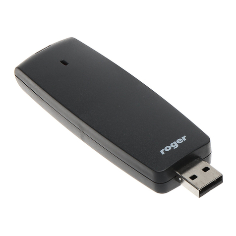
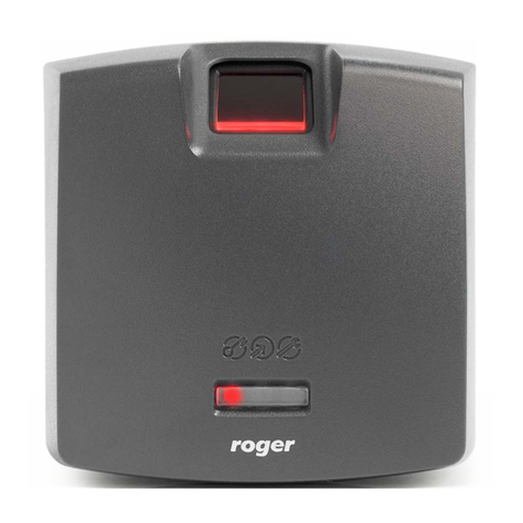
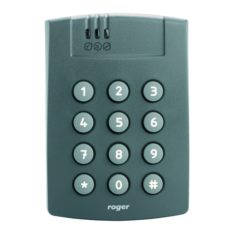
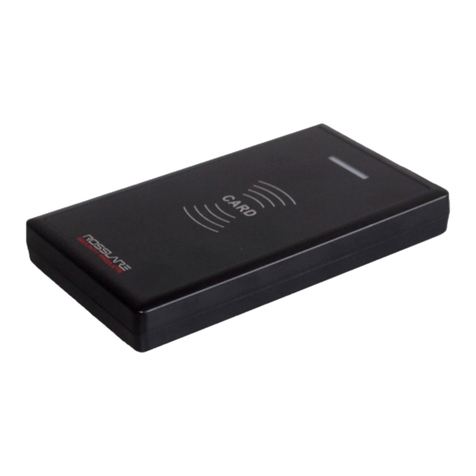
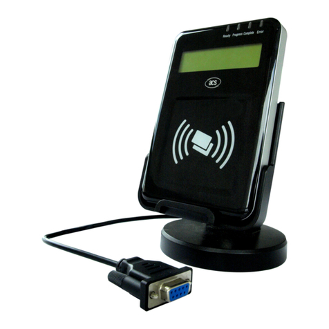
Roger PRT12LT Installation guide

PRT-LT Series
EM 125 kHz Access Readers
Firmware 1.25
Rev.G
This document refers to the following products:
-PRT12LT
-PRT12LT-BK
-PRT32LT
-PRT42LT
-PRT42LT-BK
-PRT62LT
-PRT64LT
-PRT66LT
Installation and Programming Guide

PRT-LT Series Readers fv1.25 Rev. G 2016-10-08
Page 2 from 17
1. IMPORTANT NOTES
The PRT-LT reader can be configured for several data output format however the factory shipped
new unit is pre-configured for RACS address ID=0. If required reader can be reconfigured
manually using Memory Reset procedure. Comparing with PRT-EM series access terminals the PRT-
LT series readers doesn’t support standalone operating mode.
Note: If after power up the LED SYSTEM is lit and accompanied with repeated sound it means
that contents of reader’s memory is corrupted. In this case reader must be initialized and
configured from the scratch.
1.1. COMPATIBILITY RULES
Always check the firmware and hardware version for which manual is dedicated. Using wrong
version of manual may cause that device will not behave as described in document.
1.2. ABOUT THIS MANUAL
This manual is dedicated for all versions of PRT-LT readers: with keypad and without keypad. No
matter if the PRT-LT readers have built-in keypad or not they represents the same logical
functionality. The only difference between various types of PRT-LT readers is limited to their
mechanical construction, environment in which they can be installed and keypad which exist in
some PRT-LT units.
2. GENERAL DESCRIPTION
The PRT-LT readers have been designed for use in access control installations to enable user
identification via EM 125 KHz (and compatible) proximity cards and/or PIN-s. The PRT-LT reader
works as a slave unit serving a sole purpose of reading cards/PIN-s then providing subsequent
transmission of such collected data to host ACU for further processing. Reader offers several data
transmission formats including popular Wiegand/Magstripe data protocols.
2.1. FEATURES
2.1.1. General
·EM 125 KHz proximity cards (EM4100/4102 compatible)
·Up to 10..15 cm reading range (*)
·Outdoor and indoor installations (*)
·26/32/32 reversed/34/42/66 bit Wiegand data formats
·Magstripe data format (ABA Track II emulation)
·RACS data output format (Roger format)
·Various options for transmission of PIN-s and keys
·LED control input
·BUZZER control input
·Tamper switch
·CE approval
(*) – depends on individual reader type
2.2. PROXIMITY CARDS
The PRT-LT was designed for EM 125 KHz proximity cards compatible with EM 4100/4102
transponders. Reader returns card number without check sum bits. Card number is transmitted
starting from the LSB to MSB and if required (it depends on the data output format selected for the
given reader) can be supplemented with leading zeros or reduced on the MSB positions.
2.3. FUNCTION KEYS
Some of the PRT-LT readers are equipped with two (e.g. PRT12LT) or one (PRT42LT and PRT42LT-
BK) function keys: [F1]- marked with door bell icon and [F2] – marked with the light bulb icon. The
function of each function keys depends on the reader’s operation mode.

PRT-LT Series Readers fv1.25 Rev. G 2016-10-08
Page 3 from 17
When in RACS Mode, pressing function key will cause transmission of the relevant code to the
host controller which can further take adequate action (e.g. trigger door bell, light etc.). The host’s
reaction for function key always depends on its configuration.
When in Wiegand or Magstripe modes, pressing the F1/F2 causes following codes send over the
output lines:
For Wiegand:
·F1=C hex
·F2=D hex
For Magstripe:
·F1=FF FF FF FF BC hex (1099511627708 dec)
·F2=FF FF FF FF BD hex (1099511627709 dec)
2.4. OPERATING MODES
The PRT-LT offers following data transmission formats:
·Wiegand 26bit
·Wiegand 32bit, normal mode (from MSB to LSB)
·Wiegand 32bit, reverse order (from LSB to MSB)
·Wiegand 34bit
·Wiegand 42bit
·Wiegand 66bit
·Magstripe (ABA Track II emulation, also called Clock & Data)
·RACS (for communication with PR series of controllers from Roger)
Wiegand Formats
When employing Wiegand transmission format, data is
send to the host using sequences of pulses transmitted
over CLK and DTA lines (which in this case are called
DATA1 and DATA0). Depending on the selected version of
the transmission format, the reader can send 26, 32, 34,
42 or 66 bits to the host.
Note: For card codes which require more bits than the
number of bits available in the selected data transmission
format, reader omits the most significant bits (MSB-s) of
the card code. As a result transmission from a reader is
not the same as full card code.
In Wiegand format, a dual color LED STATUS lights
steady in red, LED OPEN is controlled by IN1 while
buzzer is controlled by IN2. Both inputs (IN1 and IN2) are
triggered by connecting them to supply minus. In addition, whenever card is read or PIN is entered
reader activates momentary LED SYSTEM and buzzer.
Magstripe Formats
When employing Magstripe transmission format, data is
transferred to the host using electric signal waves
transmitted over the CLK and DTA lines. In Magstripe
format a dual color LED STATUS lights steady in red,
LED OPEN is controlled by IN1 while buzzer is
controlled by IN2. Both inputs (IN1 and IN2) are
triggered by supply minus. In addition, whenever card is
read or PIN is entered reader activates momentary LED
SYSTEM and buzzer. Card code is always transmitted
as a whole number
PRT-LT Series Readers fv1.25 Rev. G 2016-10-08
Page 4 from 17
RACS Format
When employing RACS format, the PRT-EM unit
communicates with the host via CLK/DTA lines. Unlike
in the Wiegand and Magstripe formats, the PRT-LT
unit using RACS format requires an individual address
(ID=0…3) to be set during configuration of the reader.
With RACS format, communications between the
reader and the host is bilateral, this allows controller to
monitor communication. The reader’s LED-s and the
buzzer are controlled by the host unit, unless the
reader has lost communication with the host.
Note: When all LED-s are flashing it indicates that
reader lost communication with the host unit.
When in RACS mode triggering of the IN1 disables reading of the card and keypad. This input can
be used for temporary disabling of the reader. The IN2 is not used in RACS mode.
3. CONFIGURING THE READER
3.1. MEMORY RESET
The Memory Reset erases entire contents of the reader’s memory and enables for programming
of the reader’s operating mode.
Memory Reset procedure:
1. Power down the unit
2. Remove all connections from CLK and IN1 lines
3. Connect CLK to IN1
4. Restore power, reader will generate continuous beep
5. While LED OPEN (green) is flashing and accompanied with continues sound
disconnect CLK from IN1, after this step reader’s memory is erased and filled with
default values
6. Wait till LED SYSTEM will start flashing
7. Enter three digits which will configure the reader for the required operating mode, (with
every entered digit reader generates two beeps). Optionally, if the programmed reader
is not equipped with the keypad emulate these three digits using method of multiple
card reading (see details in section below)
8. Once the previous step is completed reader automatically ends the Memory Reset and
enters normal operation

PRT-LT Series Readers fv1.25 Rev. G 2016-10-08
Page 5 from 17
3.2. PROGRAMMING THE PRT-LT READERS WITHOUT KEYPAD
Although some PRT-LT readers are not equipped with keypad still they can be programmed
manually according to the same programming procedures as readers with keypad. The difference
in programming is so that instead of pressing certain keys (like you normally do when
programming readers with keypad) you must emulate keys by multiple readings of the any
proximity card (this card will be latter called Programming Card). So called Programming Card can
be any proximity card – once you read it during programming continue to use it later during entire
cycle of programming. Of course, next time you will perform programming again you can use the
same or another prox. card as Programming Card. For example in order to emulate key [9] you
must read the designated Programming Card 9-times (simply present it to the reader and take it
back 9-times) and then wait approx. 3 seconds for the reader to generate a confirmation signal
(two beeps) which means that series of card readings were accepted as an equivalent of a single
key press and the reader is waiting for the next step of the programming procedure.
Key Emulation Method
[1] Read Programming Card 1-time
[2] Read Programming Card 2-times
[3] Read Programming Card 3-times
[4] Read Programming Card d 4-times
[5] Read Programming Card 5-times
[6] Read Programming Card 6-times
[7] Read Programming Card 7-times
[8] Read Programming Card 8-times
[9] Read Programming Card 9-times
[0] Read Programming Card 10-times
[*] Read Programming Card 11-times
[#] Read Programming Card 12-times
Note: Each time you complete the sequence of multiple readings of the
Programming Card wait for the reader to generate confirmation signal (two
beeps) which will confirm that reader has accepted series of card readings as
the emulation of a single key press.
Example: In order to emulate following programming sequence [*][1][0][ID][#] where ID=113 do
following:
1. [*]: Read 11-times your Programming Card and then wait for two beeps
2. [1]: Read 1-time your Programming Card and then wait for two beeps
3. [0]: Read 10-times your Programming Card and then wait for two beeps
4. [1]: Read 1-time your Programming Card and then wait for two beeps
5. [1]: Read 1-time your Programming Card and then wait for two beeps
6. [3]: Read 3-times your Programming Card and then wait for two beeps
7. [#]: Read 12-times your Programming Card and then wait for two beeps

PRT-LT Series Readers fv1.25 Rev. G 2016-10-08
Page 6 from 17
3.2.1. Reader Operating Modes
The factory new reader is pre-configured for RACS address ID=0 however whenever required it
can be changed using Memory Reset procedure. There are following operation modes available for
the PRT-LT series reader:
Code Operating mode Description
000 Online mode: RACS address ID=0
Reader operates as a slave unit connected to the host
controller that requires RACS data transmission format.
001 Online mode: RACS address ID=1
002 Online mode: RACS address ID=2
003 Online mode: RACS address ID=3
020
Online mode: Magstripe Reader operates as a slave unit connected to the host
controller which requires Magstripe data transmission
format, keys are not transmitted.
021
Online mode: Magstripe UNITEK Reader operates as a slave unit connected to a host
controller which requires Magstripe data transmission,
keys transmitted as single digits, format is compatible with
specification of UNITEK controllers (with transmission of
PIN-s).
10x Online mode: 26 bit Wiegand
Reader operates as a slave unit connected to the host
controller that requires relevant Wiegand data
transmission format.
11x Online mode: 34 bit Wiegand
12x Online mode: 42 bit Wiegand
13x Online mode: 66 bit Wiegand
14x Online mode: 32 bit Wiegand
(no parity)
15x
Online mode: 32 bit Wiegand
reverse (from LSB to MSB, no
parity)
Note: For Wiegand data formats the second digit of the operating mode code (marked as X) specifies the
method which reader employs when transmitting PIN-s or keys. For details regarding methods of PIN
transmission refer to table below.

PRT-LT Series Readers fv1.25 Rev. G 2016-10-08
Page 7 from 17
PIN/keys transmission options
X Description Details
X=0
1-10 digits long PIN,
transmitted in BCD format
Each key pressed is buffered in reader’s memory; with a press of a [#]
key reader transmits entire PIN code. The PIN code is transmitted as a
BCD coded number.
X=1
1-12 digits PIN, transmitted
in binary format
Each key pressed is buffered in reader’s memory; with a press of a [#]
key reader transmits entire PIN code. The PIN code is transmitted as a
binary number.
X=2
Each key pressed is
transmitted separately as
4-bit number plus 2 control
bits
Each key pressed is immediately transmitted to the host controller as a
sequence of 6 bits (EXXXXP) where XXXX represents the code of the
pressed key supplemented by two control bits (E and P). The E
represents the even bit calculated from the first half of a transmitted
code where P represents the parity of a second half of the bit stream.
This format is compatible with HID 5355 series readers, option: With
Parity. Key coding as in Table B (below).
X=3
Each key pressed is
transmitted separately as
4-bit number
Each key pressed is immediately transmitted to the host controller as a
sequence of 4 bits (XXXX) which represent the code of the pressed key,
no control bits added. This format is compatible with HID 5355 series
readers, option: Without Parity. Key coding as in Table B (below).
X=4
Each key pressed is
transmitted separately as
8-bit number with parity
Each key pressed is immediately transmitted to the host controller as a
sequence of 10 bits (EXXXXXXXXP) where XXXXXXXX represents the
code of the pressed key supplemented by two control bits (E and P). The
E represents the even bit calculated from the first half of a transmitted
code where P represents the parity of a second half of the bit stream.
Key coding as in Table A (below).
X=5
Each key pressed is
transmitted separately as a
8-bit number without parity
bits
Each key pressed is immediately transmitted to the host controller as a
sequenc
e of 8 bits (XXXXXXXX) where XXXXXXXX represents the code of
the pressed key supplemented by two control bits (E and P). The E
represents the even bit calculated from the first half of a transmitted
code where P represents the parity of a second half of the bit stream.
Key coding as in Table A (below).
X=6
1-6 keys long PIN
transmitted as Wiegand 26
bit stream with control bits
1-6 keys long PIN, each key represented by 4-bit long codes (key codes
according to table B). Reader sends data after six keys are pressed or
earlier when # key is pressed. Reader wait max ca. 15 seconds for each
key press. Key’s buffer is cleared if no keys have not been entered
within ca. 15 seconds.
Examples:
Keys entered “1234#” – code transmitted “001234”
Keys entered “123456” – code transmitted “123456”
X=7
1-4 keys long PIN
transmitted as Wiegand 32
bit stream without control
bits
1-4 keys long PIN, each key represented by 8-bit long codes (key codes
according to table A). Reader sends data after four keys are pressed or
earlier when # key is pressed. Reader wait max ca. 15 seconds for each
key press. Key’s buffer is cleared if no keys have not been entered
within ca. 15 seconds.
Examples:
Keys entered “123#” – code transmitted “0123”
Keys entered “123456” – code transmitted “123456”

PRT-LT Series Readers fv1.25 Rev. G 2016-10-08
Page 8 from 17
Table A: 8-bit key coding
Key HEX BIN
0 F0 11110000
1 E1 11100001
2 D2 11010010
3 C3 11000011
4 B4 10110100
5 A5 10100101
6 96 10010110
7 87 10000111
8 78 01111000
9 69 01101001
* 5A 01011010
# 4B 01001011
F1 3C 00111100
F2 2D 00101101
Table B: 4-bit key coding
Key ASCI BIN
0 0 0000
1 1 0001
2 2 0010
3 3 0011
4 4 0100
5 5 0101
6 6 0110
7 7 0111
8 8 1000
9 9 1001
* A 1010
# B 1011

PRT-LT Series Readers fv1.25 Rev. G 2016-10-08
Page 9 from 17
3.3. INSTALLATION GUIDELINES
·Reader should be installed in such a way to assure physical access to the connection cable
·A new factory delivered unit is configured for RACS address ID=0 however data output
format can be changed whenever required using Memory Reset procedure
·The PRT-LT reader should be mounted near the supervised door on a vertical piece of
supporting structure
·Disconnect power supply before making any electrical connections
·Be aware that when installing the reader directly on the metal type surface card reading
distance will deteriorate
·For installations on a metal surface you can place a non-metallic 10 mm thick spacer (a
plastic/plaster plate etc.) between the reader and the supporting structure
·For installations with two readers to be mounted on the opposite sides of the same wall and
aligned along the same geometrical axis, place a metal plate between them and make sure
none of two readers has direct contact with it (allow min. 10 mm space)
·For best results mount the proximity readers at least 0.5 m apart
·With its relatively weak electromagnetic field generation, reader should not cause any
harmful interference to operation of other equipment. However, its card reading
performance can be affected by other interference generating devices, esp. radio waves
emitting equipment or CRT computer monitors
·If card reading performance of the reader deteriorates (e.g. reduced reading range or
incorrect readings) consider reinstallation in a new location.
Connection terminal assignments
Wire
Color
Label Function
Green CLK DATA 0 line for Wiegand, CLOCK for Magstripe and RACS
Brown DTA DATA 1 line for Wiegand, DATA for Magstripe and RACS
Yellow IN1 Input line; in Wiegand and Magstripe formats this line controls LED OPEN .
Line is active when shorted to ground
Pink IN2 Input line; in Wiegand and Magstripe formats this line controls internal sunder
of the reader. Line is active when shorted to ground
Red +12V Supply input plus
Blue GND Supply input minus
Grey TAMP Tamper switch contacts, normally closed, isolated, IP67, 24V/50mA. Contact
became open when unit is detached from the place of installation or upper part
of enclosure is open
White
Note: For screw terminals assignments see additional drawings later in this document.

PRT-LT Series Readers fv1.25 Rev. G 2016-10-08
Page 10 from 17

PRT-LT Series Readers fv1.25 Rev. G 2016-10-08
Page 11 from 17

PRT-LT Series Readers fv1.25 Rev. G 2016-10-08
Page 12 from 17

PRT-LT Series Readers fv1.25 Rev. G 2016-10-08
Page 13 from 17

PRT-LT Series Readers fv1.25 Rev. G 2016-10-08
Page 14 from 17

PRT-LT Series Readers fv1.25 Rev. G 2016-10-08
Page 15 from 17

PRT-LT Series Readers fv1.25 Rev. G 2016-10-08
Page 16 from 17
Technical Specification
Supply voltage Nominal 12VDC, min,/max. range 10-15 VDC
Current consumption
(average)
PRT12LT: 65mA
PRT12LT-BK: 45mA
PRT32LT: 65 mA
PRT42LT: 65 mA
PRT42LT-BK: 45mA
PRT62LT: 45mA
PRT64LT: 65mA
PRT66LT: 45 mA
Reading distance PRT62LT: up to 12 cm, others: up to 15 cm
Note: Reading distance is defined for good quality proximity cards
placed in optimal position against the reader. For all PRT-LT readers
optimal card position is in the front of the reader (card surface
parallel to front of the reader)
Anti-sabotage protection
(Tamper)
NC contact, 50mA/24V, IP67
Proximity cards EM 125KHz (EM4100/4102 compatible)
Communication distance Between ACU and PRT reader: max. 150 m
Between main PRT reader and external PRT reader: max. 150 m
Environmental class
(according to EN 50131-1)
Class IV, outdoor-general, temperature: -25°C- +60°C, relative
humidity: 10 to 95% (non condensing)
Class I, Indoor, temperature: +5°C- +40°C, relative humidity: 10 to
95% (non-condensing)
PRT12LT/PRT12LT-BK: Class IV
PRT32LT: Class I
PRT42LT/PRT42LT-BK: Class I
PRT62LT: Class IV
PRT64LT: Class IV
PRT66LT: Class IV
Dimensions H x W x D PRT12LT/PRT12LT-BK: 150.5 X 46 X 23 mm
PRT32LT: 105 X 105 X 31
PRT42LT/PRT42LT-BK: 151.5 X 45 X 20.5 mm
PRT62LT: 100 X 45 X 25 mm
PRT64LT: 115 X 80 X 35 mm
PRT66LT: 85 X 85 X 27 mm
Weight PRT12LT/PRT12LT-BK: 150g
PRT32LT: 140g
PRT42LT/PRT42LT-BK: 90g
PRT62LT: 100g
PRT64LT: 120g
PRT66LT: 120g
Approvals CE

PRT-LT Series Readers fv1.25 Rev. G 2016-10-08
Page 17 from 17
Ordering Codes
PRT12LT Outdoor proximity reader with keypad, laser engraved long durability silicon
rubber keypad, two function keys, dark grey ABS enclosure, pig-tail cable
PRT12LT-BK The same as PRT12LT but without keypad
PRT32LT Indoor proximity reader with keypad, light grey top/dark grey bottom, reader can
be re-armed on the filed to non-keypad version, ABS enclosure, screw terminals
PRT42LT Indoor proximity reader with plastic keypad, one function key, dark grey ABS
enclosure, screw terminals
PRT42LT-BK The same as PRT42LT but without keypad, one function key
PRT62LT Outdoor, miniature proximity reader without keypad, dark gray ABS enclosure,
pig-tail cable
PRT64LT Outdoor, proximity reader with keypad, dark gray ABS enclosure, screw terminals
PRT66LT Outdoor, proximity reader without keypad, dark gray ABS enclosure, screw
terminals
Product History
Hardware Firmware Date Description
V1.0 fv1.25 29/10/09 Initial product version
Contact
Roger sp. z o.o. sp. k.
82-400 Sztum
Gosciszewo 59
Tel.: +48 55 272 01 32
Fax: +48 55 272 01 33
Technical support PSTN: +48 55 267 01 26
e-mail: support@roger.pl
The symbol of a crossed-through waste bin on wheels means that the product must be
disposed of at a separate collection point. This also applies to the product and all
accessories marked with this symbol. Products labeled as such must not be disposed of with
normal household waste, but should be taken to a collection point for recycling electrical
and electronic equipment. Recycling helps to reduce the consumption of raw materials, thus
protecting the environment.
This manual suits for next models
7
Table of contents
Other Roger Card Reader manuals

Roger
Roger RFT1000 User manual

Roger
Roger PRTxxMF Series User manual

Roger
Roger HRT82MF User manual

Roger
Roger PRTxxLT series User manual

Roger
Roger PRT12EM Operating and maintenance instructions

Roger
Roger MCT12E User manual

Roger
Roger RUD-3 User manual

Roger
Roger RUD-2 User manual

Roger
Roger PRTXXEM User manual

Roger
Roger PRT12MF-DES User manual