Rohloff SPEEDHUB 500/14 User manual

SPEEDHUB 500/14
I
"Quicker than the surf"
France 1994. The atmosphere at the "Tour de France" was exhilarating and working with the
teams and mechanics was exciting too. Our
30km of beautiful sandy beach lay ahead of us. It is a great feeling to have the waves roll out
under the bottom bracket!
Rohloff S-L-T 99 chan has proven a success with
its reliability! So at last, a couple of quiet days on the Atlantic coast. Why not take the Moutain
bike on the beach?!Crazy idea, yes! Riding exactly where the surf runs out! After just 200m,
total stand still! The rear wheel is stuck fast in the wet sand. Changing the gears impossible!
Derailleur gears won’t work when you are stuck! The next wave came and both rider and bike
received the first salt-water shower. Chain and sprockets are grinding full of fine sand. The
next wave came - now nothing works. The waves were rolling in faster than we could change
gears.
Still, it must feel great to have the waves roll out under the bottom-bracket. This idea didn't let
go of me.
The lights were now burning bright and late into the night. The construction department in the
Rohloff Company was working overtime. Successful gear changes and sprocket
combinations were investigated. Mountainbike, downhill, touring and everyday riders were
asked along with sports physicians: How many gears do you need and what has a gear hub got
to be capable of in order to achieve maximum riding fun? 1997: findally we had our answer
and put it to the test! Guess where...
The rear wheel is stuck fast in the wet sand. The first wave is coming. Change the gears down
while stuck. 1st gear, gentle on the pedals, riding further - 2nd - 3rd - 4th... These gears are
quicker than the surf!

II
SPEEDHUB 500/14
T I P -Owners Manual -
-Videos
Newest version
This Owners Manual is also available in a variety of other
languages. Should you require a different version, you can
download it from our homepage under:
www.rohloff.de > Service > Downloads > Documentation
The following languages are available:
-English
-German
-Dutch
-French
-Italian
-Russian
The newest version of this Manual is available on the web under:
www.rohloff.de > service > downloads > documentation > owners manual
Further to the manual, the most important work, service and repairs on the
SPEEDHUB 500/14 are shown in short films on the web.
www.rohloff.de > Technology > Workshop > Videos ...
Rohloff
III
SPEEDHUB 500/14
General Use
Technical Information
Owners Manual
WS 2.13E 2013-06
Mounting
Repairs
Service
Appendix

IV
Introduction
Securing to the frame
Cable routing
With the in the fast lane ...................................................... 1Rohloff SPEEDHUB 500/14
Riding with the Rohloff SPEEDHUB 500/14
Technical data
Safety information ............................................................................................................ 3
Changing gears ................................................................................................................. 5
Riding noises .................................................................................................................... 6
Break in period ................................................................................................................. 6
Pushing the bike ................................................................................................................ 6
Wearable parts ................................................................................................................... 6
Maintenance and care ....................................................................................................... 7
Transport/Info for the tour ................................................................................................ 9
Wheel removal ................................................................................................................ 11
Wheel installation ........................................................................................................... 14
Technical data ................................................................................................................. 17
Weight comparison/Comparison of mechanical efficiency ............................................ 18
Sprocket ratios ................................................................................................................ 19
Smallest permitted sprocket ratios .................................................................................. 19
Table of distance travelled per crank revolution (20", 26" and 28") .............................. 20
Derailleur gears in comparison to .................................... 21
in comparison to derailleur gears ..................................... 22
Interchangable parts system ............................................................................................ 23
Axle types ....................................................................................................................... 24
Torque securing .............................................................................................................. 25
Frame types ..................................................................................................................... 27
Mounting necessities OEM2 .......................................................................................... 30
Internal gear mech .......................................................................................................... 31
External gear mech ......................................................................................................... 32
Rohloff SPEEDHUB 500/14
Contents
V
Rohloff SPEEDHUB 500/14 versions
The wheel
Particular components
Special applications
All mounting processes
Maintenance of the Rohloff SPEEDHUB 500/14
Important service procedures
Appendix
Explaining the model codes ............................................................................................ 33
Advantages of the separate options ................................................................................ 38
Model variations ............................................................................................................. 39
Wheel stability ................................................................................................................ 41
Spoke lengths .................................................................................................................. 42
Calculating the spoke length ........................................................................................... 43
Determining the inner rim diameter ............................................................................... 44
Contents .......................................................................................................................... 49
Contents .......................................................................................................................... 86
Contents .......................................................................................................................... 96
Trouble shooting ........................................................................................................... 119
Bolt/tool info ................................................................................................................. 124
Wheel lacing for rims with a European spoke hole patter ........................................... 125
Wheel lacing for rims with a French spoke hole pattern .............................................. 126
Technical Data .............................................................................................................. 127
Pointers on the Serial No. ............................................................................................. 128
Grub screw of the External Gear Mech ........................................................................ 129
Notes.............................................................................................................................. 135
Index ............................................................................................................................. 136
with disc brake ................................................................. 37
Which components are recommended? .......................................................................... 45
Particulars ....................................................................................................................... 47
.................................................. 132
Rohloff SPEEDHUB 500/14
The correct spoke choice .............................................................................................. 130
Possible causes for flange breakages on bicycle hubs
Contents

1
Rohloff SPEEDHUB 500/14
Rohloff
CC DB OEM mounted in a frame with
adjustable OEM dropouts
Introduction
Warranty of the Rohloff SPEEDHUB 500/14
Each has an individual Serial No. Either on the hub shell
sticker (<~ No. 74770) or engraved (>~ No. 74771) upon the hub shell.
All entitlements to a guarantee are deleted if this serial No. Can not be produced.
Warranty claims can only be processed if the guarantee card can be presented with the
hub.
Further information on the guarantee card can be found in the appendix under “Pointers on
the Serial No.”.
To help us keep tabs on theft, it is advisable to register the Serial No. With us by way of
the guarantee card.
A more precise explanation of the guarantee conditions can be found on the guarantee card
itself which is included with every purchased.
Rohloff SPEEDHUB 500/14
A T T E N T I O N
2
With the Rohloff SPEEDHUB 500/14 in the fast lane
This handbook covers everything of interest about the It
contains important information over the use, the component choice, the mounting, the service
and the repairs. Should you still have any questions or queries after reading this handbook
than please contact your local dealer or visit us on the web under .
Due to us constantly improving our products, the shape of the parts or the contents of the
package may vary from those illustrated in this handbook. We kindly ask you to show some
consideration.
Rohloff SPEEDHUB 500/14.
www.rohloff.de
The first chapter
you will find everything you need to know about riding with the
In the following sections
you will find all the technical information needed to select the correct version of the
for your needs.
In the chapters
you will find all the technical information needed for the mounting and service of the
.
Please read the important safety information carefully.
Riding with the
- Technical data
- Securing to the frame
- Shifter cable routing
- variations
- The wheel
- Which components are recommended
- Special applications
- Mounting
- Service
- Repairs
Rohloff SPEEDHUB 500/14
Rohloff SPEEDHUB 500/14.
Rohloff SPEEDHUB 500/14
Introduction
Please read the important safety information before riding off!
Every bicycle equipped with a should come complete with
the following:
-Aguarantee card (with dealers stamp and Serial Number).
-An owners Manual for the .
-An oil filling tube.
Rohloff SPEEDHUB 500/14

3
Safety information
Bike riding is fun but it is also tied up with dangers. When your bike is not regularly
maintained and kept in good condition, these dangers increase. These dangers, however, can
be prevented when you read this handbook and the following safety information carefully. A
incorrect fitment of the vital components could result in a crash, with possible life threatening
injuries.
All the bolts must be secured to the given tightening torques.
– If a chain tensioner is in use at the rear, a chain guide must be used in conjunction up front to
prevent the chain from springing off the chainring.
– On rear suspension frames the chain must be kept at a suitable length that allows the rear
triangle to move the full amount of shock travel.
Mounting
– We recommend all fitting and assembly of our products should be carried out by a
professionally qualified workshop.
– Improper work and customizing may result in malfunction and this in turn could lead to
accidents occuring.
– Please make sure that you have the correct model for your type
of bike frame.
–
– The smallest permitted sprocket ratio must not be undercut.
– When filling the with oil for the first time as well as when
changing the oil, make sure you use only oils as recommended for the
Before riding with your please follow the next few steps in order
to truly trust the products service.
– Let your bike be regularly checked by a specialist workshop to make sure that it functions
safely.
– When starting off, especially after a gear change, you must check the gear has engaged
properly.
– Make sure you carry out the safety checks on all the other mounted components of your
bike.
– Before a long journey or tour, a test ride must be taken. Through this process any mounting
mistakes or loss of functions can be noticed and corrected. Also see ‘
– When utilizing a bicycle equipped with a ‘ belt transmission, it is
important to adhere to the manufacturers instructions printed within their Owners Manual.
Rohloff SPEEDHUB 500/14
Rohloff SPEEDHUB
Rohloff SPEEDHUB 500/14.
Rohloff SPEEDHUB 500/14
Usage
Transport/Info for
the tour’.
Gates Carbon Drive’
Riding with the SPEEDHUB 500/14
4
Check regularly:
– That the is correctly and securely mounted in the frame (quick
release axle max. 7Nm or threaded axle max. 35Nm).
–
– That the hubs torque securing system is correctly fastened to the frame.
– That the brake surfaces are free from oil and grease.
– That the shifter cables and connectors are correctly and securely connected (bayonet
connectors or external gear mech).
– That the parts on your bike are not damaged or failing to function properly as the result of an
accident. The use of damaged parts can result in further accidents occuring.
Rohloff SPEEDHUB 500/14
That all hub cap screws are correctly tightened, especially on versions of the
that incorporate the use of a brake disc.
DB Rohloff
SPEEDHUB 500/14
Rohloff SPEEDHUB 500/14
Rohloff
CC DB OEM mounted in a frame with
adjustable OEM dropouts
Riding with the SPEEDHUB 500/14

5
A T T E N T I O N
Changing gears
All 14 gears of the are selectable through one twist shifter, so that
in one turn it is possible to change up or down by one or more gears.
The mark on the twist shifter casing next to the gear numbers informs the user of which gear
has been selected. The assembly instructions show the twist shifter being fitted to the right
hand side of the handlebars, however, in special circumstances it is possible to fit the twist
shifter to the left hand side. When rotating the twist shifter in the direction of #14, a harder,
faster gear is selected. When rotating the twist shifter in the direction of #1, an easier, slower
gear is selected.
In contrast to other gear systems on the market, with the there is
no delay between gear selection on the twist shifter and gear change in the hub. The moment
the notch can be felt in the twist shifter, the gear has been changed. Therefore a quick and
failure free gear change is possible whilst riding and also when stationary.
hilst
with pressure on the pedals is not
necessary when being used appropriately. However due to the robust construction of the
changing gear under pressure is possible and is not harmful to
the hub. It is however possible that when changing gears under high pressure the hub could
accidentally fall into a neutral gear, this is due to the coupling elements not seating correctly
into the next elements and therefore rebounding back. If this occurs the rider could lose
balance and crash. Changing gears under high pressure is at the riders own risk.
If changing up and down slowly or under high pressure between the gears #7 and #8, it is
possible to fall momentarily into gear #11 or #14.
Rohloff SPEEDHUB 500/14
When changing, gear coupling elements inside the hub must move and when there is more
pressure on the pedals it is obvious there is more pressure on these coupling elements resulting
in a harder gear change. W stationary or when there is less pressure on the pedals, the twist
shifter has less resistance and therefore a lighter gear change is possible. In a situation
whereby it is not possible to reduce the pressure on the pedals (e.g. hill climbing), it is still
possible to change gear quickly and smoothly. Simply change gear when the cranks are in a
straight up-down position where hardly any pressure is being applied upon the pedals.
Changing gear with the
Particulars:
Riding with the SPEEDHUB 500/14
6
Riding noises
Break in period
Pushing the bike
Wearable parts
When riding in particular gears, one of two different types of riding noise could be heard.
Construction characteristics prove that in most gears a free-spinning noise can be heard which
is particularly noticable in gears #5, #6 and #7. When riding with a higher pressure upon the
pedals, a higher frequency can be heard through the gears #1 to #7 which is typical for
straight-toothed precision gears. Through different frame types these noises can be of
different volumes in regard to noise transfer (the tubes of the frames react as a resonator for the
sound waves). Different noises are noticable whilst freewheeling depending on which gear
you have currently selected. This is due to different parts of the gear mechanism rotating
within the hub.
All the gears and coupling elements of the are built from
specially hardened steel and are precision finished. In the first 1000km use, the
loses microscopic particles from all functioning components as part of
the hubs last fine filing. After this process is completed the riding noises quieten and the
changing of gears becomes easier. During this process it is not necessary to take extra special
care.
Should the bike be pushed, it is possible that the cranks could also start to turn. This occurs due
to the hub seal automatically activating the sprocket. Bad seals and a very light running
bottom bracket make it easier for the cranks to turn. A drop of lubricant change
assistant fluid (Art.No. 8402) through the holes in the sprocket onto the hub seal will reduce
this acivating effect.
The wearable parts are: The sprocket, chainring, jockey wheels on the chain tensioner, shifter
cables and the brake disc. How quick the parts wear is down to how the product is used and
cared for (pressure, dirt, weather and care). To guarantee the safe function, these parts must be
replaced as soon as they are no longer capable of performing correctly. Let the workings of
your bike be regularly checked over by a professional bike workshop.
Rohloff SPEEDHUB 500/14
Rohloff
SPEEDHUB 500/14
Rohloff
Riding with the SPEEDHUB 500/14

7
Maintenance and care
The gears of the are protected from dust and harmfull moisture
due to running in a oil bath. The maintenance and care of the system is limited to the
following points:
Chain and chain tensioner (where applicable) should in regard to regular use (at the latest
after riding in rain) be cleaned and relubricated.
The cable box of the external gear mech should be demounted approx. every 500km,
cleaned and the cable pulley lightly greased from the hub-facing side.
The shifter cable tension should be regularly checked, and when neccessary altered by the
cable adjusters.
The shifter cables are made from high-quality stainless steel and run in a nylon
liner. They must not be greased or oiled. The stainless steel/nylon combination runs
service-free.
The is filled with 25ml of This exact
amount of oil is optimum for both the bearings and gears of the
We suggest that every 5000km or annually, an oil change should be carried out. Therefore we
guarantee the balance of used oil and penetrated moisture will exit (see chapter ‘Service’,
paragraph 1- ‘Oil change’).
Clean only with water and gentle cleaning fluids. Do not use brushes or abrasive materials for
cleaning purposes.
Rohloff SPEEDHUB 500/14
Rohloff
Rohloff
Rohloff SPEEDHUB 500/14 Rohloff SPEEDHUB OIL.
Rohloff SPEEDHUB 500/14.
Changing the oil in the
Cleaning the
Rohloff SPEEDHUB 500/14:
When using a high pressure wash or steam cleaning, water may pass through the seals into
the hubs centre. For this reason, these cleaning processes are not advisable. Should a high
pressure wash be used, the oil should be thoroughly checked to make sure that all possible
inpregnated water is removed from within the . This is achieved best
by repetitively carrying out the oil-change procedure.
SPEEDHUB 500/14
A T T E N T I O N
Riding with the SPEEDHUB 500/14
8
5
34
21
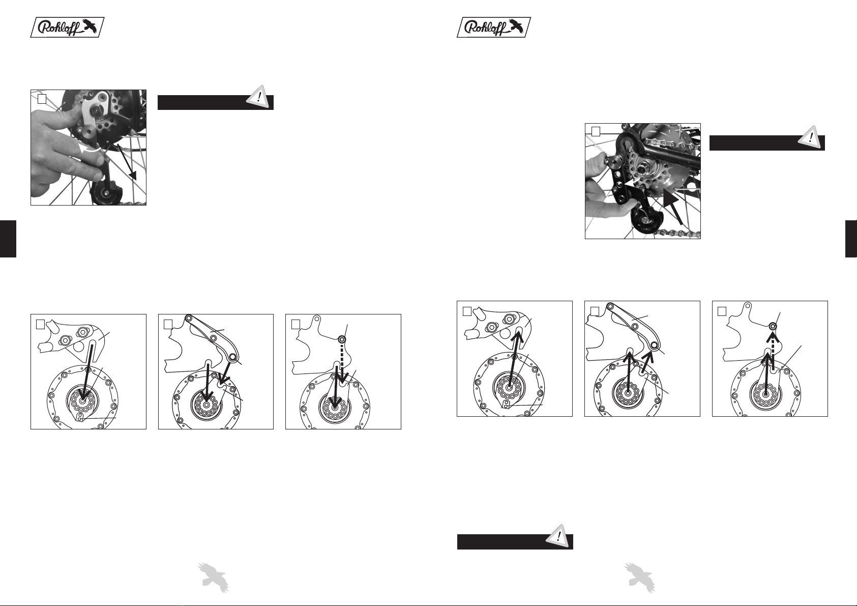
On the versions with an internal
gear mech the cable adjusters are
to be found on the cable guide.
This can be found on the left hand
chain stay or attached to the left
hand brake boss of the frame.
On the versions with an external
gear mech the cable adjusters are
to be found on the cable box which
sits directly on the left hand side of
the Rohloff SPEEDHUB 500/14.
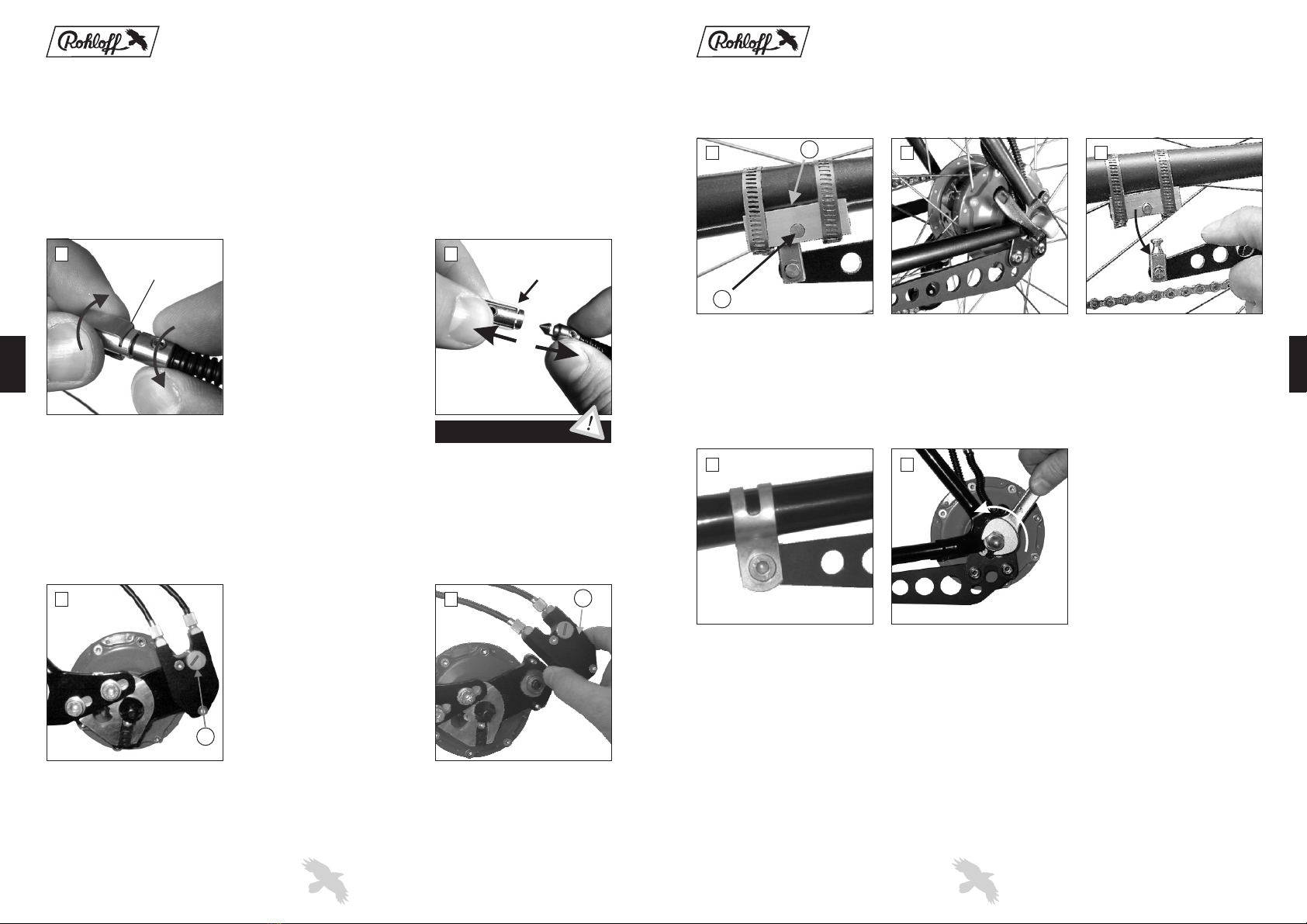
To lubricate the chain tensioner
place a drop of oil on the left and
right side of the upper jockey
wheel on the pivot point.
Rohloff SPEEDHUB 500/14
versions with external gear mech:
To lubricate the cable pulley
bearing remove the cable box and
place a little grease on the parts
arrowed in the diagram above.
When lubricating the chain place a
thin thread of lubricant on the
outside of the chain over the centre
rollers, this process is carried out
quicker and easier when running
the chain backwards whilst
applying the lubricant.
Maintenance and care
The shifter cable tension can be
altered by the cable adjusters.
Winding the cable adjusters out
increases cable tension.
The mark
on the twist shifter body can be
aligned to the correct gear number
without altering the cable tension
by winding one cable adjuster in
and the other out.
Too much cable tension raises the
amount of friction within the
shifter cables and in turn raises the
force needed on the twist shifter to
select other gears.
For the
lightest possible gear change, the
tension should be just enough
that on the twist shifter there is
approx. 2mm rotational play
when in a selected gear.
A T T E N T I O N
Riding with the SPEEDHUB 500/14
A T T E N T I O N
When using a disc brake in conjunction with the , the hub cap screws should be
checked that they are correctly tightened before every ride.
To reduce the chance of a flange breaking due to unequal spoke tension, we recommend that this is regularly
checked by a professional bicycle mechanic.
Rohloff SPEEDHUB 500/14

9
Transportation
If transporting a bike fitted with a care should be taken that the
rear wheel is transported in an upright position. In a car or an aeroplane, there could be great
changes in the air temperature/pressure. When the wheel lies on its side, oil could seep out of
the seals because the oil is sitting directly over these seals on either the left or the right side.
Transportation in the upright position will prevent the air temperature/pressure in having an
effect over the If it is not possible to transport the wheel in the
upright position due to according packaging requirements, don't worry. The leakage of oil will
not cause any damage.
The has proved from the start that it is the optimum gear system,
especially for tours and long journeys due to its durability, long life and the strength of the
final wheel itself. Of course, good materials should always be used, so that the other parts on
the bike start out not ruined, dirty, over lubricated, worn, so that their function is impaired or
even damaged. Therefore, we suggest that in regard to poor parts on the bike you should
always carry a few important tools with you. Our service team is on the net and you can Email
us at We endeaver to help with any technical problems and, when
neccessary, ship spare parts out all over the world. However, due to extremely high postage
costs or lack of service in some countries, this is not always possible. For this reason you
should take into consideration carrying spare parts (in case of accident damage or excessive
wear), this handbook and also a range of tools along for the tour.
- 2mm allen key (male/female connectors, cable pulley screws)
- 2.5mm allen key (twist shifter securing screws)
- 3mm allen key (drain screw)
- 5mm allen key (securing bolts for torque arm/chain tensioner)
- 8mm wrench (for turning the shifting rod)
- 15mm wrench (for axle nuts where applicable)
- Chain lubricant and grease
- Torx TX20 (all other bolts of the )
- Oil change kit (Art. #8410)
- Sprocket tool (Art. #8501)
- Spare chain and sprocket, spokes and shifter cables
- Internal gear mech: spare hub cables (Art. #8271) or with a quick-change axle ring
(after Serial Number 25300) Hub cable Easy Set (Art. #8573) or the complete axle ring set
(Art. #8572)
Rohloff SPEEDHUB 500/14,
Rohloff SPEEDHUB 500/14.
Rohloff SPEEDHUB 500/14
Info for the tour
Tools for on the go:
For long distance journeys the following should also be taken along:
Riding with the SPEEDHUB 500/14
10
Emergency repairs on the go
Several repairs can be improvised in case of emergencies
Remove the axle plate and the cable pulley, then with an 8mm wrench select a suitable
gear (e.g. gear #7). Riding further is now possible using this one gear.
Pull a hub cable until a suitable gear is found . R
Remove the cable box and use an
Use an M6 nut and bolt or improvise by using binding wire.
Loss of oil through sweat oil or the light leakage of oil through the seals is harmless.
Therefore, travelling further until the next oil change (at 5000km intervals) is possible.
See point 14 of ‘oil leakage’in the appendix.
Breaking of a hub cable (internal gear mech):
Breaking of a shifter cable (internal gear mech):
Safety ring (and pin) of the quick release on the torque arm (where applicable):
Loss of oil:
(e.g. gear #7) iding further is now possible
using this one gear.
Join the hub cable and the shifter cable together with the use of an electric cable connector
or binding wire.
8mm wrench select a suitable gear (e.g. gear #7). Riding
further is now possible using this one gear.
Male or female connector lost or damaged (internal gear mech):
Breaking of a shifter cable (external gear mech):
Riding with the SPEEDHUB 500/14

11
E
D
21
1 2
Separating the gear mech involves
opening the bayonet connectors.
To do this easily, select a middle
gear, so that these connectors are
in an easily reachable position.
Next, to open the connectors, twist
the male and female parts 90° in
opposite directions whilst pulling
them apart.
Spring C
1.1 Separating the internal gear mech:
1.2 Separating the external gear mech:
Separating the gear mech involves
removing the cable box. Cable box
sits over a hexagonal peg which
joins it to the external transfer box
E
.
The wheel should be removed in
gear #14 to make remounting the
wheel easier. Loosen knurled head
screw and remove cable box .D
Wheel removal
To remove the rear wheel, please take note of the following steps:
1. Separate the gear mech ................................................................................. 1.1 or 1.2
2. Loosen axle and where appropriate the torque arm .................................. 2.1 or 2.2
3. Removal of the wheel from the frame .................................................. 3.1 and/or 3.2
When opening the connectors, do
not hold the female connector by
the spring as this makes separating
the connectors considerably more
difficult.
A T T E N T I O N
Riding with the SPEEDHUB 500/14
Bayonet
connector
12
F
G
1 2 3
1 2
2. Loosening the torque support on versions with a long torque arm
2.1 CC versions
Open the quick release by
pushing the locking pin from the
inside of the frame in an outward
direction away from the wheel.
G
FOpen the axle quick release lever.
Loosen the torque arm clamp bolt
by unscrewing it with a 4mm allen
key.
Loosen the axle nuts with a 15mm
wrench.
Pull the torque arm down in the
direction of the arrow to release it
from the frame.
Riding with the SPEEDHUB 500/14
2.2 TS versions

13
1 2 3
1
3.2 Wheel removal - OEM and OEM2 versions
No loosening of a torque arm is neccessary with these versions. Simply open the quick release lever (CC versions)
or loosen the axle nuts (TS versions).
On the OEM versions, the axle and
the support block are released
together from the OEM dropout.
On the OEM2 versions with
the axle
falls out of the dropouts at the
same time as the axle plate seat
falls away from the
support peg.
Rohloff SPEEDBONE,
Rohloff
SPEEDBONE
On the OEM2 versions with just a
support bolt, the axle falls out the
dropout at the same time as the
axle plate seat falls away from the
support bolt.
3.1 Removal of the wheel from the frame
Remove the wheel from the
dropouts and the chain from the
sprocket.
A chain tensioner prevents the easy
removal of the rear wheel (when
mounted). The chain tensioner
must be pulled backwards in the
direction of the arrow to allow the
sprocket to pass the chain
tensioner. When, however, it is a
DH chain tensioner, the mounting
bolt must be loosened before the
rear wheel can be removed.
A T T E N T I O N
Riding with the SPEEDHUB 500/14
OEM
dropout
Axle peg
Support
block
Rohloff
SPEEDBONE
Axle-
plate
seat
Support
peg
Support bolt
Axle-
plate
seat
14
1
1
32
Wheel installation
mounting the wheel to the frame:
2. Securing of the axle and, where appropriate, the torque arm .................. 2.1 or 2.2
Please take note of the following steps when
1. Installation of the wheel into the frame ............................................... 1.1 and/or 1.2
3. Joining of the gear mech ............................................................................... 3.1 or 3.2
1.2 Wheel installation - OEM or OEM2 versions
On the OEM or OEM2 versions, the axle and the torque support are installed together.
1.1 Wheel installation
Place the wheel into the dropouts,
taking care that the chain is sitting
properly on the sprocket and that
the hub cables do not get clamped
between the dropouts and the axle.
On the OEM versions, the axle
must enter the long OEM dropout
first, followed by the support block
into the same slot.
On the OEM2 versions with
take care
that the
support peg lines up with the axle
plate seat as the axle is entered into
the dropouts.
Rohloff SPEEDBONE,
Rohloff SPEEDBONE
On the OEM2 versions with just a
support bolt, take care that the
support bolt lines up with the axle
plate seat as the axle is entered into
the dropouts.
After installing the wheel, close the quick release lever (CC versions - tightening torque: max. 7Nm/62in.lbs.) or
tighten the axle nuts (TS versions - tightening torque: max. 35Nm/310in.lbs.).
A chain tensioner prevents the easy
installation of the rear wheel (when
mounted). The chain tensioner must
be pulled backwards in the
direction of the arrow to allow the
sprocket to pass the chain tensioner.
When, however, it is a DH chain
tensioner, then the mounting bolt
must be loosened before the rear
wheel can be installed.
Before closing the quick release lever or tightening the axle nuts, check that
both sides of the axle sit properly in the dropouts and that the wheel runs in
the center of the frame.
A T T E N T I O N
A T T E N T I O N
Riding with the SPEEDHUB 500/14
OEM
dropout
Axle peg
Support
block
Support bolt
Axle-
plate
seat
Rohloff
SPEEDBONE
Axle-
plate
seat
Support
peg

15
2F
G
31
1 2
2. Securing the long torque arm
2.1 CC versions
Close the quick release
G
Fby
pushing the quick release pin in
the direction of the wheel, so that
the outside of the pin is flush with
the quick release block.
Swing the torque arm into the
quick release block in the direction
of the arrow shown.
Swing the torque arm in the
direction of the securing clamp
until it is possible to push the
securing bolt through the holes of
the and the .
Check that the axle is sitting
properly in the dropouts.
clamp torque arm
2.2 TS versions
Close the quick release lever (max.
7Nm)
Tighten the axle nuts (tightening
torque: 35Nm/310in.lbs.).
With the nut and washer, tighten
the torque arm securing bolt with
4mm allen key (tightening torque:
6Nm/51in.lbs.).
Before closing the quick release
lever (max. 7Nm/62in.lbs.) or
tightening the axle nuts (max.
35Nm/310 in.lbs.), check that both
sides of the axle sit properly in the
dropouts and that the wheel runs in
the centre of the frame.
A T T E N T I O N
Riding with the SPEEDHUB 500/14
16
I
H
E
D
1 2
1 2
To rejoin the gear mech, the male
and female bayonet connectors
must be joined back together. Pay
attention not to cross these cables
over when joining the hub and
shifter cables together. Push the
male connector into the female
connector until the spring locks
them together. Take care not to
hold the female connector by the
spring.
3.1 Joining together of the internal gear mech:
3.2 Joining together of the external gear mech:
Rejoining the gear mech involves
remounting the cable box. Place
the twist shifter into gear #14 then
place cable box over the
hexagonal peg so that the two
locating pegs sit into the two
holes in the back of the cable box.
Turn the twist shifter back and
forth around gear #14 until the
cable box falls into place over the
hexagonal peg. Lastly tighten up
the knurled head screw.
E
I,
H
Should all 14 gears not be
selectable after fitting the cable
box, it will be down to the hub or
the twist shifter not being in gear
#14. There are two methods to
correct this.
Spring C
Method 1:
Remove cable box and turn the
twist shifter into gear #1. Refit
cable box and shift until it can no
longer be turned. If you are not in
gear #14 of the twist shifter then
disconnect the cable box and turn
the twist shifter into gear #14.
Now reconnect the cable box to
have access to all 14 gears.
Method 2:
Remove the cable box and turn the
twist shifter into gear #14. Take an
8mm wrench and use it to turn the
hexagonal peg on the external
transfer box anticlockwise until it
reaches the end stop. Now the hub
is in gear #14, so the cable box can
be remounted.
A T T E N T I O N
Riding with the SPEEDHUB 500/14

17
Technical Data
Technical data
Number of gears: . . . . . . . . . . . . . . . . . . . . . . . . . . . . . . . . 14
Gear increases: . . . . . . . . . . . . . . . . . . . . . . . . . . . . . . . . . even 13.6%
Range of gears: . . . . . . . . . . . . . . . . . . . . . . . . . . . . . . . . . 526%
Frame spacing: . . . . . . . . . . . . . . . . . . . . . . . . . . . . . . . . . 135mm
Number of spoke holes: . . . . . . . . . . . . . . . . . . . . . . . . . . . 32 / 36
Spoke flange distance: . . . . . . . . . . . . . . . . . . . . . . . . . . . . 60mm, symmetrical
Spoke hole circle diameter: . . . . . . . . . . . . . . . . . . . . . . . . Ø100mm
Spoke hole diameter: . . . . . . . . . . . . . . . . . . . . . . . . . . . . . Ø2.7mm
Axle overall width CC: . . . . . . . . . . . . . . . . . . . . . . . . . . . 147mm
Hollow axle inner diameter:. . . . . . . . . . . . . . . . . . . . . . . . Ø5.5mm, for quick release lever
Mounting bolt hole circle diameter: . . . . . . . . . . . . . . . . . . Ø65mm
Brake disc mounting bolts:. . . . . . . . . . . . . . . . . . . . . . . . . 4 M8 0.75
Distance between dropout and center disc mount: . . . . . . . 16mm (IS1999)
Weight: . . . . . . . . . . . . . . . . . . . . . . . . . . . . . . . . . . . . . . . 1700g (CC), 1800g (CC EX), 1825g (CC DB)
Oil amount: . . . . . . . . . . . . . . . . . . . . . . . . . . . . . . . . . . . . 25ml max.
Number of sprocket teeth: . . . . . . . . . . . . . . . . . . . . . . . . . 16 (optional: 13, 15 and 17)
Chainline: . . . . . . . . . . . . . . . . . . . . . . . . . . . . . . . . . . . . . 54mm (58mm with 13tooth sprocket)
Smallest permittable gear ratios (normal 26”): . . . . . . . . . . (transmission ratio ~2.10)
(Riders over 100kg/tandem): . . . . . . . . . . . . . . . . . . . . . . . 42/17, 40/16, 38/15, 34/13 (transmission ratio ~2.50)
Maximum input torque: . . . . . . . . . . . . . . . . . . . . . . . . . . . 100Nm
Gear control: . . . . . . . . . . . . . . . . . . . . . . . . . . . . . . . . . . . via twist shifter
Twist shifter angle per gear change: . . . . . . . . . . . . . . . . . . 21°/273°
Gear control transfer: . . . . . . . . . . . . . . . . . . . . . . . . . . . . . over two shifter cables (pull-pull system)
Shifter cable movement per gear change: . . . . . . . . . . . . . . 7.4mm/96,2mm
Inner gear ratios (hub rotation per sprocket rotation):
1: 0.279
Spoke flange width: . . . . . . . . . . . . . . . . . . . . . . . . . . . . . . 3.2mm
Axle diameter at dropout:. . . . . . . . . . . . . . . . . . . . . . . . . . 9.8mm
Axle overall width TS: . . . . . . . . . . . . . . . . . . . . . . . . . . . . 171mm ( with axle plate TS long 179mm)
Axle thread TS: . . . . . . . . . . . . . . . . . . . . . . . . . . . . . . . . . M10 1
Center disc mounting diameter: . . . . . . . . . . . . . . . . . . . . . Ø52mm
Sprocket thread:. . . . . . . . . . . . . . . . . . . . . . . . . . . . . . . . . M34 6 P6, tolerance 6H
Sprocket type: . . . . . . . . . . . . . . . . . . . . . . . . . . . . . . . . . . for bicycle chain 1/2" 3/32” (ISO Nr. 082)
Gear #
Gear #2: 0.316
Gear #3: 0.360
Gear #4: 0.409
Gear #5: 0.464
Gear #6: 0.528
Gear #7: 0.600
Gear #8: 0.682
Gear #9: 0.774
Gear #10: 0.881
Gear #11: 1.000
Gear #12: 1.135
Gear #13: 1.292
Gear #14: 1.467
We reserve the right to change the technical specifications without prior warning
x
x
x
x x
.
36/17, 34/16, 32/15, 28/13
18
Weight comparison
Comparison of mechanical efficiency
The is with a weight of 120g per gear, the lightest gear hub on the market. The gear range
is the same as high quality 27 gear derailleur systems due to the 14 gears within the hub being evenly spaced out at
13.6% increases. With the
Rohloff SPEEDHUB 500/14
www.rohloff.de
there is no longer a need for the following parts:
-Front and rear derailleur
-Two shifters including
-Rear hub with cassette
-Small and middle chainrings
-The total average weight of all these components is approx. 1600g.
The weight of a fitted CC OEM including twist shifter, shifter cables and cable guide is
approx. 1820g.
The comparison between the and the derailleur system shows only a slight increase in
weight. For that, the user receives a:
- Service-free,
- dirt-free full-encapsulated,
- user-friendly gear system and
- high reliability
- alongwith a long life span.
The mechanical efficiency* and consequently the size of the loss of the is entirely
comparable with that of the derailleur system.
The losses of a derailleur system consist of the friction caused by the bottom bracket, chain, cassette and the hub
bearings. The amount of friction loss depends on the size of the sprockets, the angle of the chain line and condition of
wear. In reality this proves to be 1 - 5%, leaving the derailleur system with a working efficiency lying between 95%
and 99%.
The losses of the are caused by the fricion coming from the bottom bracket, chain and
gearbox. Here, however, the chain runs in a straight line from just one chainring reducing sideways friction on the
sprockets. Most of the friction occurs when all the planetary gear sets are used within the gearbox. The overall
average loss of the gears within the is approximately 1 - 5%, leaving the working
efficiency between 95% and 99%.
The is, therefore, consequently an optimum choice for the everyday and sports rider.
* More detailed info over the working efficiency is to be found on the web under .
Technical Data

19
The tables or the following formula can be used to compare the to a derailleur gear
system:
Rohloff SPEEDHUB 500/14
Ratio of the derailleur gear system = C S
Ratio of the = IGR C S
The sprocket ratio on the (e.g. 42:16) converts the slow rotational speed at the crank into
a fast rotational speed at the sprocket and reduces the input torque for the in the same
proportion. To prevent overstraining the hub, a minimum sprocket ratio of 2.10 must be used. With the available
sprockets these minumum ratios are achieved by: . This resembles a derailleur
transmission of 20:34. Larger chainrings can be used without exceptions.
¸
¸Rohloff SPEEDHUB 500/14
Rohloff SPEEDHUB 500/14
x
Smallest permissible sprocket ratios
If mounted on a tandem or if the rider weighs over 100kg, the following sprocket ratios must not be undercut:
34:13, 38:15, 40:16, 42:17. This equates to a transmission factor of 2.50.
36:17, 34:16, 32:15 and 28:13
Sprocket ratios
The has a range of gears, that means gear #14 is 5.26 times greater than gear #1.
The 14 gears are evenly spaced out over this range in 13.6% increases. Through the choice of chainring and sprocket
in use, the
When the particular wheel/sprocket/chainring size and gear is not listed in the tables, then the following formula can
be used to calculate the exact :
Formula key:
W = Wheel circumference
C = Chainring size
S = Sprocket size
IGR = Inner gear ratio listed in the following table
Rohloff SPEEDHUB 500/14
526%
can be tuned for the specific riding purpose. The
comes standard with a 16 tooth sprocket. 13, 15 and 17 tooth sprockets are available as alternatives.
In the following tables the distance travelled per crank revolution is listed for gears #1 and #14. The listed distance
travelled per crank revolution is shown in the tables for a variety of sprocket ratios and wheel sizes (20", 26" and 28"
wheels).
distance travelled per crank revolution of the
Rohloff SPEEDHUB 500/14 Rohloff SPEEDHUB 500/14
Distance travelled per crank revolution = W C S IGRx x¸
Inner gear ratio IGR = hub revolutions per sprocket revolutions of the Rohloff SPEEDHUB 500/14
gear # 1 2 3 4 5 6 7 8 9 10 11 12 13 14
IGR 0.279 0.316 0.360 0.409 0.464 0.528 0.600 0.682 0.774 0.881 1.000 1.135 1.292 1.467
A T T E N T I O N
Technical Data
20
Technical Data
Table of distance travelled per crank revolution wheels (wheel circumference 1.51m)20"
Table of distance travelled per crank revolution wheels (wheel circumference 2.06m)26"
Table of distance travelled per crank revolution wheels (wheel circumference 2.18m)28"
Solo cyclists under 100kg
Sprocket
Chainring from to from to from to from to
28 tooth 0,91m - 4,77m
30 tooth 0,97m - 5,11m
32 tooth 1,04m - 5,45m 0,90m - 4,73m
34 tooth 1,11m - 5,79m 0,95m - 5,02m 0,90m - 4,71m
36 tooth 1,17m - 6,13m 1,01m - 5,32m 0,95m - 4,98m 0,89m - 4,69m
38 tooth 1,23m - 6,47m 1,07m - 5,61m 1,00m - 5,26m 0,94m - 4,95m
40 tooth 1,30m - 6,81m 1,12m - 5,91m 1,05m - 5,54m 0,99m - 5,21m
42 tooth 1,36m - 7,16m 1,18m - 6,20m 1,10m - 5,81m 1,04m - 5,47m
44 tooth 1,42m - 7,50m 1,23m - 6,50m 1,16m - 6,09m 1,09m - 5,73m
46 tooth 1,49m - 7,84m 1,29m - 6,79m 1,21m - 6,37m 1,14m - 5,99m
48 tooth 1,55m - 8,18m 1,35m - 7,09m 1,26m - 6,64m 1,19m - 6,25m
50 tooth 1,62m - 8,52m 1,40m - 7,38m 1,32m - 6,92m 1,24m - 6,51m
52 tooth 1,68m - 8,86m 1,46m - 7,68m 1,37m - 7,20m 1,29m - 6,77m
13 tooth 15 tooth 16 tooth 17 tooth
Solo cyclists under 100kg
Sprocket
Chainring from to from to from to from to
28 tooth 1,31m - 6,89m
30 tooth 1,40m - 7,38m
32 tooth 1,49m - 7,87m 1,30m - 6,82m
34 tooth 1,59m - 8,36m 1,38m - 7,25m 1,29m - 6,80m
36 tooth 1,68m - 8,85m 1,46m - 7,67m 1,37m - 7,20m 1,29m - 6,77m
38 tooth 1,78m - 9,35m 1,54m - 8,10m 1,44m - 7,59m 1,36m - 7,15m
40 tooth 1,87m - 9,84m 1,62m - 8,53m 1,52m - 7,99m 1,43m - 7,52m
42 tooth 1,96m - 10,33m 1,70m - 8,95m 1,60m - 8,39m 1,50m - 7,90m
44 tooth 2,06m - 10,82m 1,78m - 9,38m 1,67m - 8,79m 1,57m - 8,28m
46 tooth 2,15m - 11,31m 1,86m - 9,81m 1,75m - 9,19m 1,64m - 8,65m
48 tooth 2,24m - 11,81m 1,94m - 10,23m 1,82m - 9,59m 1,72m - 9,03m
17 tooth13 tooth 15 tooth 16 tooth
Solo cyclists under 100kg
Sprocket
Chainring from to from to from to from to
28 tooth 1,24m - 6,51m
30 tooth 1,33m - 6,97m
32 tooth 1,41m - 7,44m 1,23m - 6,45m
34 tooth 1,50m - 7,91m 1,30m - 6,85m 1,22m - 6,42m
36 tooth 1,59m - 8,37m 1,38m - 7,25m 1,29m - 6,80m 1,22m - 6,40m
38 tooth 1,68m - 8,83m 1,45m - 7,65m 1,36m - 7,18m 1,28m - 6,76m
40 tooth 1,77m - 9,30m 1,53m - 8,06m 1,44m - 7,55m 1,35m - 7,10m
42 tooth 1,86m - 9,76m 1,61m - 8,46m 1,51m - 7,93m 1,42m - 7,46m
44 tooth 1,94m - 10,23m 1,68m - 8,86m 1,58m - 8,31m 1,49m - 7,82m
46 tooth 2,03m - 10,69m 1,76m - 9,27m 1,65m - 8,69m 1,55m - 8,18m
48 tooth 2,12m - 11,16m 1,84m - 9,67m 1,72m - 9,06m 1,62m - 8,53m
13 tooth 15 tooth 16 tooth 17 tooth
Table of distance travelled per crank revolution for wheels ->
Internet -> www.rohloff.de/service/downloads/documentation
650B and 29"

21
Technical Data
Derailleur gears in comparison to Rohloff SPEEDHUB 500/14
The table shows which sprocket ratio on the must be used to resemble
the smallest transmission of a derailleur gear system.
Rohloff SPEEDHUB 500/14
The table shows which sprocket ratio on the must be used to resemble
the largest transmission of a derailleur gear system.
Rohloff SPEEDHUB 500/14
Smallest sprocket ratio of
derailleur gears
22/34 32/13 36/15 38/16 40/17
24/34 34/13 38/15 42/16 44/17
26/34 36/13 42/15 44/16 48/17
20/32 32/13 36/15 38/16 40/17
22/32 34/13 38/15 40/16 42/17
24/32 36/13 42/15 44/16 46/17
26/32 38/13 44/15 48/16 50/17
20/30 32/13 36/15 40/16 42/17
22/30 36/13 40/15 44/16 46/17
24/30 38/13 44/15 46/16 50/17
26/30 42/13 48/15 50/16 54/17
Largest sprocket ratio of
derailleur gears
42/11 34/13 40/15 42/16 46/17
44/11 36/13 42/15 44/16 48/17
46/11 38/13 44/15 46/16 50/17
48/11 40/13 46/15 48/16 52/17
50/11 42/13 48/15 50/16 54/17
52/11 42/13 50/15 52/16 56/17
54/11 44/13 52/15 54/16 58/17
42/12 32/13 36/15 40/16 42/17
44/12 34/13 38/15 40/16 44/17
46/12 34/13 40/15 42/16 46/17
48/12 36/13 42/15 44/16 48/17
50/12 38/13 44/15 46/16 50/17
52/12 40/13 46/15 48/16 52/17
54/12 40/13 48/15 50/16 54/17
Gear #14 Rohloff SPEEDHUB 500/14
sprocket ratio
Gear #1 Rohloff SPEEDHUB 500/14
sprocket ratio
22
Technical Data
Rohloff
The table shows which smallest and largest sprocket ratio of derailleur gears resembles the existing transmission of
the
SPEEDHUB 500/14 in comparison to derailleur gears
Rohloff SPEEDHUB 500/14.
Sprocket ratio
(chainring/sprocket)
Rohloff SPEEDHUB 500/14
Gear #1 resembles a
derailleur gear sprocket
ratio of
Gear #14 resembles a
derailleur gear sprocket
ratio of
38/13 22/26 24/30 48/11 52/12
40/13 22/25 24/27 50/11 54/12
42/13 22/24 24/26 52/11 56/12
44/13 22/23 24/25 54/11 60/12
46/13 22/22 or 24/24 58/11 or 62/12
48/13 22/21 24/23 60/11 64/12
50/13 22/20 24/22 62/11 68/12
52/13 22/19 24/21 64/11 70/12
54/13 22/18 24/20 68/11 74/12
38/15 22/32 24/34 42/11 44/12
40/15 22/30 24/32 44/11 46/12
42/15 22/28 24/30 46/11 50/12
44/15 22/26 24/29 48/11 52/12
46/15 22/25 or 24/28 50/11 or 54/12
48/15 22/24 24/26 52/11 56/12
50/15 22/23 24/25 54/11 58/12
52/15 22/22 24/24 56/11 62/12
54/15 22/21 24/23 60/11 64/12
38/16 22/34 24/36 38/11 42/12
40/16 22/30 24/34 40/11 44/12
42/16 22/30 24/32 42/11 46/12
44/16 22/28 24/32 44/11 48/12
46/16 22/27 or 24/30 46/11 or 50/12
48/16 22/26 24/28 48/11 52/12
50/16 22/25 24/27 50/11 56/12
52/16 22/24 24/26 52/11 58/12
54/16 22/23 24/25 54/11 60/12
40/17 22/34 24/36 38/11 42/12
42/17 22/32 24/34 40/11 44/12
44/17 22/30 24/34 42/11 46/12
46/17 22/29 or 24/32 44/11 or 48/12
48/17 22/27 24/30 46/11 50/12
50/17 22/26 24/29 48/11 52/12
52/17 22/25 24/28 50/11 54/12
54/17 22/24 24/27 52/11 56/12

23
+
Internal gear mech External gear mech
(EX)
Interchangable parts system
There are basically two different versions of the One with a quick
release axle (CC versions) and one with a threaded axle (TS versions). The only other differences are
in the components. Due to the wide range of these componets, the can
be mounted on nearly every type of bicycle.
Rohloff SPEEDHUB 500/14.
Rohloff SPEEDHUB 500/14
Long torque arm for
mounting to standard
frames
OEM mounting for
special frames with
OEM
dropouts
Rohloff
OEM2 mounting
for frames with
international
standard disc
brake mounts
(IS2000)
For bikes using a rim brake typ
(CC / TS) on the rear wheel
For bikes using a disc brake
Typ (CC DB / TS DB) on the rear wheel
with EX - gear mech
Securing to the frame
Gear mech (two options)
Torque securing (three options)
Hub cap (two options)
24
Axle types
The is available with two different axle types. The CC versions come with a hollow axle
for use with a quick release lever. The TS versions come with a threaded axle for use with standard M10 1 nuts for
securing to the frame. The 14 gear mechanism on both the versions is primarily the same.
Rohloff SPEEDHUB 500/14
x
Rohloff SPEEDHUB 500/14 CC (quick release axle)
Rohloff SPEEDHUB 500/14 TS (threaded axle)
Securing to the frame

25
1 2 3 4 5 6 7 8 9 10 11 12 13 14
98% 82% 68% 55% 44% 34% 25% 18% 11% 5% 0% 5% 9% 12%
When the rider applies 20kg onto the pedal, he produces a crank torque of 34Nm. In gear #8 this results in
6Nm torque on the torque arm (18% ). With the same crank torque of 34Nm in gear #1 this
results in 33Nm torque on the torque arm (98% of crank torque). Gear #11 is the direct drive (1:1) the torque
on the torque arm is always zero.
of crank torque
Torque securing
With all gear hubs the axle tries to turn whilst riding. When riding in a reducing gear, the axle tries to turn backwards.
When riding in an increasing gear, the axle tries to turn forwards. The force with which the axle tries to turn is refered
to as torque. The amount of torque depends upon the force applied on the pedals and the gear selected. This torque
must be secured by some means to the frame.
On the simple three-speed hubs a flat sided axle is sufficient to secure the torque within the dropout. On a high
performance internal gear hub like the the method of securing the torque must be
considerably more stable due to the wide range of gear ratios.
The amount of torque produced is shown in the following table:
Rohloff SPEEDHUB 500/14
Torque in percent of crank torque with a 42/16 sprocket ratio
Rohloff SPEEDHUB 500/14
Rohloff
CC OEM mounted in a frame with
adjustable OEM dropouts
Backwards torque rotation see picture below or next page, pictures 1, 2 and 3
Securing to the frame
Forward rotation
Backward rotation
Gear
%
Torque
26
3)
2)
1)
B
Exclusively for frame
F and Gtypes
(see "Frame types")
OEM axleplate A (axle peg)
Exclusively
for frame types
A, B, C and D
(see "Frame types")
Standard axleplate
with long torque arm
The long torque arm is bolted behind the axleplate. The narrow end is secured to the frame by means of a clamp or a
quick release block. The axle is prevented from turning t . When removing the wheel, the
torque arm must first be released from the frame at the narrow end .
B
hrough these two points
B
A (axle peg)
Depending on the type of frame one of three options can be used to secure the torque.
1) Standard axleplate with long torque arm
2) OEM axleplate
3) OEM2 axleplate
All three anchoring options ensure the axleplate is secured to the frame in two positions to
. The first point is the axle peg that is secured to the left side dropout. This i
The difference between the three options is point . The hole pattern on the axleplates allow for individual
adjustment of the gear mechs in steps of 30°, so that nearly every frame type can receive an optimum cable routing.
prevents the axle from
rotating s the same for all three options.A
B
Securing to the frame
Mounting the SPEEDHUB 500/14 using an OEM2 axleplate is only permitted on frames with international standard
(IS1999) disc brake mounts. The OEM2 axleplate sits with its axle peg in the dropout. The axleplate seat secures
itself around the supporting peg of the or (when mounted on a bike with disc
brakes) or around the support bolt fastened through the lower brake caliper mounting hole (
A B
Rohloff SPEEDBONE
Rohloff SPEEDBONE /
MonkeyBone
MonkeyBone
when mounted on a bike
with rim brakes). When removing the wheel, the axleplate falls away from the support bolt/
and out of the dropout once the axle is loosened..
The mounting of hubs with an OEM axle plate is only possible on frames fitted with OEM dropouts. The
OEM axleplate sits in the dropout slot of the OEM dropout. The axle peg slides in first followed by the support
block into the same slot. The dropout itself prevents these two parts from turning. When removing the wheel, the
two parts fall out the dropout together once the axle has been loosened.
Rohloff
A
B
B (support block)
A (axle peg)
OEM2 axleplate
B (axleplate seat)
Exclusively for frame
types D and E
(see "Frame types")

27
B
A
C
Frame types
The requires a frame spacing of 135mm, all frames with different frame spacing or for
thru axles are not suitable for the The inner side of the left hand dropout must be flat in a
diameter of 40mm around the center of the axle so that the axle plate can sit firmly and evenly against the dropout.
There are different versions available (for the different dropout types) with the suitable
axle and axle plate along with the corresponding parts for mounting. The does not
include a brake. To mount a brake (disc or rim), the frame must have the correct brake mounts.
Rohloff SPEEDHUB 500/14
Rohloff SPEEDHUB 500/14.
Rohloff SPEEDHUB 500/14
Frame types for the long torque arm:
When the slot lenght is longer than 25mm ( ), a chain tensioner does not
have to be used as there is enough adjustment room within the slot to
tension the chain.
The following versions of the are, therefore,
suitable:
TS
TS EX
B
Rohloff SPEEDHUB 500/14
On frames with vertical dropout slots ( ) the mounting of the
normally suggests a CC quick release version (CC or
CC EX). This as opposed to the TS versions (TS and TS EX) allows for a
quicker wheel removal/installation without the use for tools.
The following versions of the , therefore,
suitable:
CC
CC EX
TS*
TS EX*
CRohloff
SPEEDHUB 500/14
Rohloff SPEEDHUB 500/14 are
On frames with horizontal dropout slots, it is only possible to mount the
in the TS threaded axle versions (TS and TS
EX). The CC versions with a quick release lever will not hold the wheel
secure enough and the wheel could be pulled crooked whilst riding.
When the slot lenght is shorter than 25mm ( ), a chain tensioner (Art.
#8250) must be fitted as there is not enough adjustment room within the
slot to tension the chain.
The following versions of the are, therefore,
suitable:
TS*
TS EX*
Rohloff SPEEDHUB 500/14
A
* These versions must be used in conjunction with a chain tensioner (Art.No. 8250) except when an eccentric BB
is being used.. The chain tensioner should be ordered with the initial product as it is not to be found in the regular
package.
Securing to the frame
Slot length
shorter than 25mm
Slot length
larger than 25mm
!
28
E
SPEEDBONE
SPEEDBONE
D
MonkeyBone
MonkeyBone
On frame types ( ) with a Horst Link, the mounting is only
possible with the use of the OEM2 axleplate.
All versions can be mounted on
this frame type, the only accessory needed is the OEM2
axleplate.
Horst Link, named after his inventor Horst Leitner.
E
Rohloff SPEEDHUB 500/14
When mounting the hub with the use of the OEM2 axle plate, the disc brake mounts will be used to secure the torque
of the hub. Therefore, permission must be obtained from the frame manufacturer to ensure that the guarantee is not
affected. The mounting instructions for the OEM2 usage must be read carefully (see "Mounting instructions for
OEM2").
Frame types for OEM2 mounting
For frames with vertical dropouts and international standard disc brake mounts (IS 1999), the use of an OEM2
axleplate is highly recommended. With this, the disc brake mount will be used to secure the torque of the hub. Two
mounting possibilities are to be decided between:
1) Mounting with a disc brake on the rear wheel
The torque is secured through the (Art. #8550), (160mm= Art. #8553/
180mm=Art. #8554), then through the disc brake mounts and secured tightly into the brake disc caliper.
2) Mounting without a disc brake on the rear wheel
The is not necessary. A support bolt secured through the lower disc brake
mount can be used to support the torque.
Rohloff SPEEDBONE MonkeyBone
Rohloff SPEEDBONE/MonkeyBone
On frames ( ) with international disc brake mounts (IS
1999), the OEM2 mounting is recommended. As an
alternative the long torque arm could also be used (see frame
type ).
All versions can be mounted on
this frame type, the only accessory needed is the OEM2
axleplate.
D
C
Rohloff SPEEDHUB 500/14
When mounting on Tandems even without the use of a disc brake, the must be
mounted and its supporting peg used to support the torque of the OEM2 axleplate. A chain tensioner must also be
mounted in conjunction with the use of the OEM2 mounting, except on frames built around an eccentric BB system.
Rohloff SPEEDBONE/Monkey Bone
A T T E N T I O N
Securing to the frame
Horst Link
A T T E N T I O N

29
F
G
min. Ø40
Ø40 Ø40 Ø40
Frame types for OEM mounting
Rigid frames with OEM dropouts are specially designed for the mounting of all
OEM versions. The long slot in the left hand dropout holds the support block of the OEM axle plate.
Rohloff Rohloff SPEEDHUB
500/14
Frame types ( ) have unadjustable OEM dropout and are specially designed for rear suspension models. A
chain tensioner must be mounted, because the distance between the chainring and sprocket varies as the rear
suspension is activated.All OEM versions are suitable for these frame types.
GRohloff
Rohloff SPEEDHUB 500/14
Frame types ( ) have adjustable OEM dropouts. With these dropouts on a hardtail frame, the need for a chain
tensioner is eliminated because the wheel (once secured into the dropout inserts) can be pulled backwards to tension
the chain. The dropout inserts are available from a variety of manufacturers with or without disc brake mounts and are
all interchangable (supply information is available under www.rohloff.de). All OEM
versions are suitable for these frame types.
FRohloff
Rohloff SPEEDHUB 500/14
All versions mounted to frame types must be used in conjunction with a chain tensioner (Art.No. 8250) except
when an eccentric BB is being used.Achain tensioner should be ordered with the initial product as it is not to be found
in the regular OEM package.
G
A T T E N T I O N
Securing to the frame
No matter what shape the left-hand dropout is, a surface of 40mm diameter around the center of the axle must be flat
to allow the axle plate to sit firmly and evenly againt the inner side of the left-hand dropout. This area is shown in the
diagram below.
A T T E N T I O N
Diagram 1: Flat left dropout surface and three different axle plates
30
C C
Ø6.2 mm
Mounting necessities OEM2
For safe OEM2 mounting with the support bolt or the /
1999
MonkeyBoneRohloff SPEEDBONE , the following points
must be well noted:
The disc brake mounts must be one piece with the dropout itself, be of international standard (IS ) and have the
following minimum dimension requirements:
When permission has not been granted by the frame manufacturer to mount the
or the support bolt through the disc brake mount, then mounting of the OEM2 versions is at your own risk.
Rohloff SPEEDBONE /
Further compatability information can be found under:
www.rohloff.de > FAQ > SPEEDHUB > Axleplates and Dropouts
MonkeyBone
Requiremental for the OEM2 mouting of the with a support bolt is the position of the
disc brake mounts. When the mount hole nearest the axle is behind a vertical line up from the axle center (d
1), then the support bolt can be used. When the hole is in front of the vertical line (d 2), then the use of the
support bolt is not permitted.
Rohloff SPEEDHUB 500/14
C
C
iagram
iagram
A T T E N T I O N
A T T E N T I O N
Securing to the frame
Fig. 1 Fig. 2
Dropout with
disc brake mounts
Position on
the correct
side Position on
the incorrect
side
Securing holes for the brake caliper
Dropout with
disc brake mounts
R > 6 mm

31
Internal gear mech
The hole pattern in the axle plate allows the adjustment of the gear mech in
steps of 30°. Therefore, an optimum cable routing can be achieved for nearly all frame types.
With the internal gear mech the shifter cables run from the twist shifter to the cable guide, which can be mounted to the
left hand brake boss or clamped to the left hand chainstay. The internal gear mech involves the use of two hub cables.
They must be connected to the shifter cables by the use of bayonet connectors which allow a quick separation for
wheel removal. The internal gear mech is not compatible with the use of a rear disc brake as the hub cables and
bayonet connectors may rub on the disc.
Cable routing
The diagrams show examples of the internal gear mech routed via the brake boss with standard, OEM and OEM2 axle
plates.
The diagram shows an example of the internal gear mech routed via the chainstay with the standard axle plate and
long torque arm using the straight type cable guide with frame clamp.
Brake boss
Left hand
brake arm
Bayonet
connectors
Cable
separated for
wheel removal
Cable guide (13°)
Hub cables
with concertina
tubes
Shifter cables
Cable guide
with frame clamp
(0°)
(Art. #8260)
Chainstay
Longer than 240mm
Longer than 240mm
32
External gear mech
Rohloff SPEEDHUB 500/14 are equipped with the external gear
mech. The hole pattern in the axle plate allows the adjustment of the gear mech in steps of 30°. Therefore, an optimum
cable routing can be achieved for nearly all frame types.
With the external gear mech the shifter cables run directly from the twist shifter to the cable box. There is no separate
cable stop necessary. For quick and easy removal of the rear wheel, the cable box can be removed from the external
transfer box. All disc brake versions (DB) of the
Mounting options with external gear mech and the standard axleplate with long torque arm
Mounting options with external gear mech and an OEM axleplate
Mounting options with external gear mech and an OEM2 axleplate
Cable box
Shifter cables Cable box
detached for
wheel removal
External transfer box
Cable routing

33
Explaining the model codes
The first part of the model codes ( ) refers to the axle type. Two different axle types
are available:
ross ountry
Hollow axle for use with a quick release lever (quick release axle)
(axle as shown in pictures 1 and 2*).
hreaded pindle axle
The following part of the model codes refers to additional hub specifications:
ternal gear mech
isc rake
With a disc brake hub cap and external gear mech EX
version ( fficial quipped anufacturer)
With CC OEM or TS OEM axleplate according axle type
only for frames with OEM dropouts
version
With CC OEM2 or TS OEM2 axleplate according axle type
anodized (polis 10/2013)
anodized
* see next page
CC/TS
Rohloff
CC: C C
TS: T S
EX: Ex
DB: D B
OEM: OEM O E M
OEM2: OEM2
Threaded axle with axle nuts M10 1 (axle as shown in picture 3*).
With external gear mech (gear mech as shown in pictures 2 and 3*).
(hub cap and gear mech as shown in picture 2*).
(axleplate as shown in picture 2*).
for frames with international standard (IS1999) disc brake mounts
(axleplate as shown in picture 3*).
andem version.
With longer shifter cables (2,5m) for tandem or recumbent use.
All versions are available in three different colors:
hed aluminum up to
anodized
x
T: T
Rohloff SPEEDHUB 500/14
silver:
black:
red:
SPEEDHUB 500/14 versions
34
1
2
3
Rohloff SPEEDHUB 500/14 TS EX OEM2 red
Standard hub cap
TS OEM2 axleplate
Threaded axle
External gear mech
Rohloff SPEEDHUB 500/14 CC DB OEM black
Disc brake hub cap
External gear mech
Quick release axle
CC OEM axleplate
The is available in different versions in accordance to the individual
requirements. Pictures 1 to 3 show examples of three possible versions.
Rohloff SPEEDHUB 500/14
Rohloff SPEEDHUB 500/14 CC silver
Internal gear mech
Quick release axle
Standard hub cap
Standard CC axleplate
with long torque arm
SPEEDHUB 500/14 versions
Other manuals for SPEEDHUB 500/14
5
Table of contents
Other Rohloff Bicycle Accessories manuals