manuals.online logo
Brands
  1. Home
  2. •
  3. Brands
  4. •
  5. Rohm
  6. •
  7. Computer Hardware
  8. •
  9. Rohm BP35C5 User manual

Rohm BP35C5 User manual

PRODUCTS
Hybrid IC
TYPE BP35C5
PAGE
1/33
TARGET SPECIFICATION
The mentioned items and the specifications may be changed without notice.
Notice
● Precaution on using ROHM Products
1) Our Products are designed and manufactured for application in ordinary electronic equipment (such as
AV equipment, OA equipment, telecommunication equipment, home electronics appliances, amusement
equipment, etc.). If you intend to use our Products in devices requiring extremely high reliability (such as
medical equipment, transport equipment, traffic equipment, aircraft/spacecraft, nuclear power controllers,
fuel controllers, car equipment including car accessories, safety devices, etc.) and whose malfunction or
failure may cause loss of human life, bodily injury or serious damage to property (“Special
Applications”), please consult with the ROHM sales representative in advance. Unless otherwise agreed
in writing by ROHM in advance, ROHM shall not be in any way responsible or liable for any damages,
expenses or losses incurred by you or third parties arising from the use of any ROHM’s Products for
Specific Applications.
2) ROHM designs and manufactures its Products subject to strict quality control system. However,
semiconductor products can fail or malfunction at a certain rate. Please be sure to implement, at your own
responsibilities, adequate safety measures including but not limited to fail-safe design against the physical
injury, damage to any property, which a failure or malfunction of our Products may cause. The following
are examples of safety measures.
[a] Installation of protection circuits or other protective devices to improve system safety
[b] Installation of redundant circuits to reduce the impact of single or multiple circuit failure
3) Our Products are designed and manufactured for use under standard conditions and not under any special
or extraordinary environments or conditions, as exemplified below. Accordingly, ROHM shall not be in
any way responsible or liable for any damages, expenses or losses arising from the use of any ROHM’s
Products under any special or extraordinary environments or conditions. If you intend to use our Products
under any special or extraordinary environments or conditions (as exemplified below), your independent
verification and confirmation of product performance, reliability, etc, prior to use, must be necessary:
[a] Use of our Products in any types of liquid, including water, oils, chemicals, and organic solvents
[b] Use of our Products outdoors or in places where the Products are exposed to direct sunlight or
dust
[c] Use of our Products in places where the Products are exposed to sea winds or corrosive gases,
including Cl2, H2S, NH3, SO2, and NO2
[d] Use of our Products in places where the Products are exposed to static electricity or
electromagnetic waves
[e] Use of our Products in proximity to heat-producing components, plastic cords, or other
flammable items
[f]Sealing or coating our Products with resin or other coating materials
[g] Use of the Products in places subject to dew condensation
4) The Products are not subject to radiation-proof design.
5) Please verify and confirm characteristics of the final or mounted products in using the Products.
6) Confirm that operation temperature is within the specified range described in the product specification.
7) ROHM shall not be in any way responsible or liable for failure induced under deviant condition from
what is defined in this document.
8) This Product may be subjected to radio wave interference from other equipment emitting radio waves.
9) This Product emits radio waves due to the specification. To use equipment emitting radio waves,
certification under the Radio Act should be obtained by region in which the Product is used. For the
standards for certification under the Radio Act to be obtained for the use of this Product, separately
contact your ROHM representative.
DESIGN
Kawabata
CHECK
APPROVAL
DATE: 12/May/2020
SPECIFICATION No.:
TARGET SPECIFICATION
REV. E
TSZ22111・04・002
PRODUCTS
Hybrid IC
TYPE BP35C5
PAGE
2/33
Notice
● Precaution for Mounting / Circuit board design
1) When a highly active halogenous (chlorine, bromine, etc.) flux is used, the residue of flux may negatively
affect product performance and reliability.
2) In principle, the reflow soldering method must be used.
● Precautions Regarding Application Examples and External Circuits
1) If change is made to the constant of an external circuit, please allow a sufficient margin considering
variations of the characteristics of the Products and external components, including transient
characteristics, as well as static characteristics.
2) You agree that application notes, reference designs, and associated data and information contained in this
document are presented only as guidance for Products use. Therefore, in case you use such information,
you are solely responsible for it and you must exercise you own independent verification and judgment in
the use of such information contained in this document. ROHM shall not be in any way responsible or
liable for damages, expenses or losses incurred by you or third parties arising from the use of such
information.
● Precaution for Electrostatic
This Product is electrostatic sensitive product, which may be damaged due to electrostatic discharge.
Please take proper caution in your manufacturing process and storage so that voltage exceeding Products
maximum rating will not be applied to Products. Please take special care under dry condition (e.g.
Grounding of human body / equipment / solder iron, isolation from charged objects, setting of Ionizer,
friction prevention and temperature / humidity control).
● Precaution for Storage / Transportation
1) Product performance and soldered connections may deteriorate if the Products are stored in the places
where:
[a] the Products are exposed to sea winds or corrosive gases, including Cl2, H2S, NH3, SO2, and NO2
[b] the temperature or humidity exceeds those recommended by ROHM
Temperature: 5C - 40C, Humidity: 40% - 60%RH
[c] the Products are exposed to direct sunshine or condensation
[d] the Products are exposed to high Electrostatic
2) Even under ROHM recommended storage condition, solderability of products out of recommended
storage time period may be degraded.
It is strongly recommended to confirm solderability before using Products of which storage time is
exceeding the recommended storage time period.
・Recommended storage condition: Temperature: 5C - 40C, Humidity: 40% - 60%RH
3) Store / transport cartons in the correct direction, which is indicated on a carton as a symbol. Otherwise
bent leads may occur due to excessive stress applied when dropping of a carton.
4) Use Products within the specified time after opening a humidity barrier bag. Baking is required before
using Products of which storage time is exceeding the recommended storage time period.
・Maximum time : 72 hours, Temperature: 5C - 40C, Humidity: 40% - 60%RH
・Baking condition: Single type: 125C, 24 hours, up to once
REV. E
SPECIFICATION No.: TARGET SPECIFICATION
TSZ22111・05・002
PRODUCTS
Hybrid IC
TYPE BP35C5
PAGE
3/33
Notice
● Precaution for product label
QR code printed on ROHM product label is for ROHM’s internal use only, and please do not use at
customer site.
● Precaution for disposition
When disposing Products please dispose them properly using an authorized industry waste company.
● Precautions Regarding Intellectual Property Rights
1) All information and data including but not limited to application example contained in this document is
for reference only. ROHM does not warrant that foregoing information or data will not infringe any
intellectual property rights or any other rights of any third party regarding such information or data.
2) ROHM shall not have any obligations where the claims, actions or demands arising from the combination
of the Products with other articles such as components, circuits, systems or external equipment (including
software)
3) No license, expressly or implied, is granted hereby under any intellectual property rights or other rights of
ROHM or any third parties with respect to the Products or the information contained in this document.
Provided, however, that ROHM will not assert its intellectual property rights or other rights against you
or your customers to the extent necessary to manufacture or sell products containing the Products, subject
to the terms and conditions herein.
● Other Matters
1) This document may not be reprinted or reproduced, in whole or in part, without prior written consent of
ROHM.
2) The Products may not be disassembled, converted, modified, reproduced or otherwise changed without
prior written consent of ROHM.
3) In no event shall you use in any way whatsoever the Products and the related technical information
contained in the Products or this document for any military purposes, including but not limited to, the
development of mass-destruction weapons.
4) The proper names of companies or products described in this document are trademarks of registered
trademarks of ROHM, its affiliated companies or third parties.
5) Return one (1) copy of this Specification with your receipt stamp put on it.
If you do not return the Specification even after three (3) months elapsed from the date of issue stated on
the cover of the Specification, ROHM shall, at its discretion, deem the contents of the Specification to
have been accepted by you.
6) Any questions as to the contents of this Specification shall be promptly resolved by consultation between
the parties.
● Scope of Warranty
ROHM Co., Ltd. (hereinafter referred to “ROHM”) shall warrant materials used in this Product and the
Product as stated below.
1) In the event that any defect in any of the said materials or this Product through analysis made at ROHM,
ROHM shall repair or replace free of charge for a period of twenty-four (24) months from the date of
shipment from the warehouse of ROHM.
2) This warranty shall not apply to any damage caused by
(a) fire, earthquake, flood, theft, or other disaster; or
(b) repair, modification, misuse, abuse, or negligence.
ROHM shall have no legal responsibility for any sort of incidental and indirect damage (such as faults in or
replacement of parts of your set product, or shipping charges of such parts) or for items that explicitly or
implicitly indicate the breach of the warranty of this Product.
REV. E
SPECIFICATION No.: TARGET SPECIFICATION
TSZ22111・05・002
PRODUCTS
Hybrid IC
TYPE BP35C5
PAGE
4/33
1. Structure
Assembly using a printed circuit board
2. Product Name
Hybrid IC
3. Model Name
BP35C5
4. Application
Telecommunication equipment
5. Function
Specified low power radio module (920 MHz band)
6. Absolute Maximum Ratings
No.
Parameter
Symbol
Rating
Unit
Condition
1
Supply voltage
VDD
-0.3 to +3.9
V
DC
2
Digital input voltage
VDIN
-0.3 to VDD+0.3
V
3
Digital output voltage
VDO
-0.3 to VDD+0.3
V
5
Digital output current
IDO
-8 to+8
mA
6
Operating temperature range
Topr
-30 to 85
°C
7
Storage temperature range
Tstg
-40 to 85
°C
(Note) The absolute maximum ratings represent values that shall not be exceeded for even an instant on all operating or
testing conditions.
Design systems with a margin for the ratings listed above.
7. Recommended Operating Conditions
No.
Parameter
Symbol
Specification
Unit
Condition
Min.
Typ.
Max.
1
Supply voltage
VDD
2.6
3.3
3.6
V
2
Operating temperature range
Ta
-30
25
85
°C
REV. E
SPECIFICATION No.: TARGET SPECIFICATION
TSZ22111・05・002
PRODUCTS
Hybrid IC
TYPE BP35C5
PAGE
6/33
10. Electrical Characteristics
Input current characteristics (Ta25°C, VDD3.3V)
Parameter
Condition
Specification
Unit
No.
Min.
Typ.
Max.
1
Current consumption
(Data rate: 150 kbps)
Transmission state (set to 20 mW)
30
40
50
mA
2
Reception state
10
20
30
mA
3
Sleep state*
(Held by register)
-
5
-
μA
Measurement was made with the terminating end of 50 ohm measuring instrument connected with the antenna
connector terminal of the module using RF cable.
Be noted that the parameter marked with “*” represents a design guaranteed value.
RF characteristics
Measurement conditions: Ta25°C and VDD3.3V
Modulation rate: 50kbps, 150 kbps
Modulation method: Binary GFSK
Channel spacing: 400 kHz
Measurement made at the antenna connector terminal of the module
Transmission characteristics (Ta25°C, VDD3.3V)
Parameter
Condition
Specification
Unit
No.
Min.
Typ.
Max.
1
Transmission output power
20 mW mode
11.0
13.0
15.0
dBm
10 mW mode
8.0
10.0
12.0
dBm
1 mW mode
0.3
1.9
3.6
dBm
2
Occupied bandwidth
n1 (50 kbps)
-
89
200
kHz
n2 (150 kbps)
-
166
400
kHz
3
Adjacent channel leakage power
[ACPR]
20 mW mode 1 channel
Bandwidth: 200 kHz
-
-
-15
dBm
4
Frequency shift [Fdev]*
50 kbps
-
25
-
kHz
150 kbps
37.5
kHz
Be noted that the parameter marked with “*” represents a design guaranteed value.
REV. E
SPECIFICATION No.: TARGET SPECIFICATION
TSZ22111・05・002
PRODUCTS
Hybrid IC
TYPE BP35C5
PAGE
7/33
Transmission characteristics (continued) (Ta25°C, VDD3.3V)
Parameter
Condition
Specification
Unit
No.
Min.
Typ.
Max.
5
Spurious emission levels
for transmission
(in 20 mW mode)
100 kHz bandwidth below 710 MHz
-
-
-36
dBm
6
1 MHz bandwidth between 710 MHz
and 900 MHz
-
-
-55
dBm
7
100 kHz bandwidth between 900 MHz
and 915 MHz
-
-
-55
dBm
8
100 kHz bandwidth between 915 MHz
and 930 MHz (except levels detuned by
400 kHz or less from the center of radio
channels (n2); provided that levels
ranging from 920.5 MHz to 922.3 MHz
and detuned by 300 kHz or less shall be
excluded)
-
-
-36
dBm
9
100 kHz bandwidth between 930 MHz
and 1 GHz
-
-
-55
dBm
10
1 MHz bandwidth between 1 GHz and
1.215 GHz
-
-
-45
dBm
11
1 MHz bandwidth over 1.215 GHz (over
second harmonic)
-
-
-30
dBm
Be noted that the parameter marked with “*” represents a design guaranteed value.
Reception characteristics (Ta25°C, VDD3.3V)
Parameter
Condition
Specification
Unit
No.
Min.
Typ.
Max.
12
Minimum receiving sensitivity
* BER<0.1%,
150 kbps mode
-
-95
-85
dBm
13
Maximum receiving input level*
150 kbps mode
0
-
-
dBm
14
Minimum power detection (ED
value) level*
-
-
-
-95
dBm
15
Power detection range*
Dynamic range
-
60
-
dB
16
Power detection accuracy*
-
-10
-
+10
dB
Be noted that the parameter marked with “*” represents a design guaranteed value.
REV. E
SPECIFICATION No.: TARGET SPECIFICATION
TSZ22111・05・002
PRODUCTS
Hybrid IC
TYPE BP35C5
PAGE
8/33
Reception characteristics (continued) (Ta=25°C、VDD=3.3V)
No.
Parameter
Condition
Specification
Unit
Min.
Typ.
Max.
17
Subsidiary emission levels
100 kHz bandwidth below 710 MHz*
-
-
-54
dBm
18
1 MHz bandwidth between 710 MHz
and 900 MHz*
-
-
-55
dBm
19
100 kHz bandwidth between 900 MHz
and 915 MHz*
-
-
-55
dBm
20
100 kHz bandwidth between 915 MHz
and 930 MHz
-
-
-54
dBm
21
100 kHz bandwidth between 930 MHz
and 1 GHz*
-
-
-55
dBm
22
1 MHz bandwidth over 1 GHz *
-
-
-47
dBm
Be noted that the parameter marked with “*” represents a design guaranteed value.
REV. E
SPECIFICATION No.: TARGET SPECIFICATION
TSZ22111・05・002
PRODUCTS
Hybrid IC
TYPE BP35C5
PAGE
9/33
11. Interface Characteristics
Terminal characteristics (design guarantee values)
(Operating supply voltage: VDD2.6V to 3.6V, Ta30C to 85C)
No.
Parameter
Symbol
Condition
Specification
Unit
Min.
Typ.
Max.
1
High-level input voltage
VIH1
(*1)
VDD x 0.7
-
VDD
V
2
Low-level input voltage
VIL1
(*1)
0
-
VDD
x0.3
V
3
High-level output voltage
VOH
IOH4mA (*2)
VDD -0.4
-
VDD
V
4
Low-level output voltage
VOL
IOL-4mA (*2)
-
-
0.4
V
(*1) Pin shown as “I” in the “I/O” column in “Pin Description” table.
(*2) Pin shown as “O” in the “I/O” column in “Pin Description” table.
UART specification
Parameter
Specification
Baud rate
115,200 bps
Data width
8 bits
Parity
Not provided
Stop bit
1 bit
HW flow control
Disabled (Default)
REV. E
SPECIFICATION No.: TARGET SPECIFICATION
TSZ22111・05・002
PRODUCTS
Hybrid IC
TYPE BP35C5
PAGE
10/33
Reset characteristics (design guarantee value)
(Operating supply voltage: VDD2.6V to 3.6V, Ta30 to 85C)
Parameter
Symbol
Condition
Specification
Unit
Min.
Typ.
Max.
RESETN pulse period
(When starting from VDD=0V)
TRPW
-
200
-
-
ns
RESETN pulse period 2 (*1)
(When starting from VDD≠0V)
TRPW2
VDD>2.6V
1
-
-
ms
(*1) When starting from VDD≠.0V, input a pulse to the RESETN signal after VDD exceeds 2.6V.
Startup time
Insert “WAIT” period of three seconds or more before the first command is issued after turning ON the power
supply or resetting.
REV. E
SPECIFICATION No.: TARGET SPECIFICATION
TSZ22111・05・002
PRODUCTS
Hybrid IC
TYPE BP35C5
PAGE
11/33
12. Channel Setting
For Japan region (ARIB STD-T108)
Region Japan Japan Japan Japan
Data Rate 50 kbps 100 kbps 150 kbps 300 kbps
n unit radio channel 1 2 2 3
Modulation Index 1 1 0.5 0.5
Channel space 200 kHz 200 kHz 200 kHz 200 kHz
F_Dev 25.0 kHz 50.0 kHz 37.5 kHz 75.0 kHz
Channel Number
Center Frequency
[kHz]
Center Frequency
[kHz]
Center Frequency
[kHz]
Center Frequency
[kHz]
24 920.6 920.7 920.7 920.8
25 920.8 920.9 920.9 921.0
26 921.0 921.1 921.1 921.2
27 921.2 921.3 921.3 921.4
28 921.4 921.5 921.5 921.6
29 921.6 921.7 921.7 921.8
30 921.8 921.9 921.9 922.0
31 922.0 922.1 922.1 922.2
32 922.2 922.3 922.3 922.4
33 922.4 922.5 922.5 922.6
34 922.6 922.7 922.7 922.8
35 922.8 922.9 922.9 923.0
36 923.0 923.1 923.1 923.2
37 923.2 923.3 923.3 923.4
38 923.4 923.5 923.5 923.6
39 923.6 923.7 923.7 923.8
40 923.8 923.9 923.9 924.0
41 924.0 924.1 924.1 924.2
42 924.2 924.3 924.3 924.4
43 924.4 924.5 924.5 924.6
44 924.6 924.7 924.7 924.8
45 924.8 924.9 924.9 925.0
46 925.0 925.1 925.1 925.2
47 925.2 925.3 925.3 925.4
48 925.4 925.5 925.5 925.6
49 925.6 925.7 925.7 925.8
50 925.8 925.9 925.9 926.0
51 926.0 926.1 926.1 926.2
52 926.2 926.3 926.3 926.4
53 926.4 926.5 926.5 926.6
54 926.6 926.7 926.7 926.8
55 926.8 926.9 926.9 927.0
56 927.0 927.1 927.1 927.2
57 927.2 927.3 927.3 927.4
58 927.4 927.5 927.5 927.6
59 927.6 927.7 927.7 927.8
60 927.8 927.9 927.9 -
61 928.0 - - -
REV. E
SPECIFICATION No.: TARGET SPECIFICATION
TSZ22111・05・002
PRODUCTS
Hybrid IC
TYPE BP35C5
PAGE
12/33
For United States region (FCC Part 15) (1/4)
REV. E
SPECIFICATION No.: TARGET SPECIFICATION
TSZ22111・05・002
Region US US US US
Data Rate 50 kbps 150 kbps 300 kbps 600 kbps
Modulation Index 1 0.5 0.5 0.4
Channel space 200 kHz 400 kHz 600 kHz 1000 kHz
F_Dev 25.0 kHz 37.5 kHz 75.0 kHz 120.0 kHz
Channel Number
Center Frequency
[kHz]
Center Frequency
[kHz]
Center Frequency
[kHz]
Center Frequency
[kHz]
0 902.2 902.4 902.6 903.0
1 902.4 902.8 903.2 904.0
2 902.6 903.2 903.8 905.0
3 902.8 903.6 904.4 906.0
4 903.0 904 905 907.0
5 903.2 904.4 905.6 908.0
6 903.4 904.8 906.2 909.0
7 903.6 905.2 906.8 910.0
8 903.8 905.6 907.4 911.0
9 904.0 906 908 912.0
10 904.2 906.4 908.6 913.0
11 904.4 906.8 909.2 914.0
12 904.6 907.2 909.8 915.0
13 904.8 907.6 910.4 916.0
14 905.0 908 911 917.0
15 905.2 908.4 911.6 918.0
16 905.4 908.8 912.2 919.0
17 905.6 909.2 912.8 920.0
18 905.8 909.6 913.4 921.0
19 906.0 910 914 922.0
20 906.2 910.4 914.6 923.0
21 906.4 910.8 915.2 924.0
22 906.6 911.2 915.8 925.0
23 906.8 911.6 916.4 926.0
24 907.0 912 917 927.0
25 907.2 912.4 917.6 -
26 907.4 912.8 918.2 -
27 907.6 913.2 918.8 -
28 907.8 913.6 919.4 -
29 908.0 914 920 -
30 908.2 914.4 920.6 -
31 908.4 914.8 921.2 -
32 908.6 915.2 921.8 -
33 908.8 915.6 922.4 -
34 909.0 916 923 -
35 909.2 916.4 923.6 -
36 909.4 916.8 924.2 -
37 909.6 917.2 924.8 -
PRODUCTS
Hybrid IC
TYPE BP35C5
PAGE
13/33
For United States region (FCC Part 15) (2/4)
Region US US US US
Data Rate 50 kbps 150 kbps 300 kbps 600 kbps
Modulation Index 1 0.5 0.5 0.4
Channel space 200 kHz 400 kHz 600 kHz 1000 kHz
F_Dev 25.0 kHz 37.5 kHz 75.0 kHz 120.0 kHz
38 909.8 917.6 925.4 -
39 910.0 918 926 -
40 910.2 918.4 926.6 -
41 910.4 918.8 927.2 -
42 910.6 919.2 - -
43 910.8 919.6 - -
44 911.0 920 - -
45 911.2 920.4 - -
46 911.4 920.8 - -
47 911.6 921.2 - -
48 911.8 921.6 - -
49 912.0 922 - -
50 912.2 922.4 - -
51 912.4 922.8 - -
52 912.6 923.2 - -
53 912.8 923.6 - -
54 913.0 924 - -
55 913.2 924.4 - -
56 913.4 924.8 - -
57 913.6 925.2 - -
58 913.8 925.6 - -
59 914.0 926 - -
60 914.2 926.4 - -
61 914.4 926.8 - -
62 914.6 927.2 - -
63 914.8 927.6 - -
64 915.0 - - -
65 915.2 - - -
66 915.4 - - -
67 915.6 - - -
68 915.8 - - -
69 916.0 - - -
70 916.2 - - -
71 916.4 - - -
72 916.6 - - -
73 916.8 - - -
74 917.0 - - -
75 917.2 - - -
76 917.4 - - -
77 917.6 - - -
REV. E
SPECIFICATION No.: TARGET SPECIFICATION
TSZ22111・05・002
PRODUCTS
Hybrid IC
TYPE BP35C5
PAGE
14/33
For United States region (FCC Part 15) (3/4)
Region US US US US
Data Rate 50 kbps 150 kbps 300 kbps 600 kbps
Modulation Index 1 0.5 0.5 0.4
Channel space 200 kHz 400 kHz 600 kHz 1000 kHz
F_Dev 25.0 kHz 37.5 kHz 75.0 kHz 120.0 kHz
78 917.8 - - -
79 918.0 - - -
80 918.2 - - -
81 918.4 - - -
82 918.6 - - -
83 918.8 - - -
84 919.0 - - -
85 919.2 - - -
86 919.4 - - -
87 919.6 - - -
88 919.8 - - -
89 920.0 - - -
90 920.2 - - -
91 920.4 - - -
92 920.6 - - -
93 920.8 - - -
94 921.0 - - -
95 921.2 - - -
96 921.4 - - -
97 921.6 - - -
98 921.8 - - -
99 922.0 - - -
100 922.2 - - -
101 922.4 - - -
102 922.6 - - -
103 922.8 - - -
104 923.0 - - -
105 923.2 - - -
106 923.4 - - -
107 923.6 - - -
108 923.8 - - -
109 924.0 - - -
110 924.2 - - -
111 924.4 - - -
112 924.6 - - -
113 924.8 - - -
114 925.0 - - -
115 925.2 - - -
116 925.4 - - -
117 925.6 - - -
REV. E
SPECIFICATION No.: TARGET SPECIFICATION
TSZ22111・05・002
PRODUCTS
Hybrid IC
TYPE BP35C5
PAGE
15/33
For United States region (FCC Part 15) (4/4)
Region US US US US
Data Rate 50 kbps 150 kbps 300 kbps 600 kbps
Modulation Index 1 0.5 0.5 0.4
Channel space 200 kHz 400 kHz 600 kHz 1000 kHz
F_Dev 25.0 kHz 37.5 kHz 75.0 kHz 120.0 kHz
118 925.8 - - -
119 926.0 - - -
120 926.2 - - -
121 926.4 - - -
122 926.6 - - -
123 926.8 - - -
124 927.0 - - -
125 927.2 - - -
126 927.4 - - -
127 927.6 - - -
128 927.8 - - -
13. Setting of Communication Time Limit and Carrier Sensing Time
This Product has acquired the Technical Regulations Conformity Certification with the settings listed in the table
below. The Products is not allowed to be used with any setting outside the setting range listed below.
Unit Channel
Number
Data rate setting
(Number of channels to use
at a time)
Carrier sensing
time
Transmission
time limit
Pause time
Total of
transmission time
per hour
33-61(JP)
50 kbps (n=1)
100kbps (n=2),
150kbps (n2)
300kbps (n=3)
128 μs or more
(Sensing at all
times)
400 ms or less
per transmission
2 ms or
more
360 sec. or less
With channel
hopping;
720 sec. or less
Unit Channel
Number
Data rate setting
Carrier sensing
time
Transmission
time limit
Pause time
Total of
transmission time
per hour
0-128(US)
50 kbps
150kbps
300kbps
600kbps
128 μs or more
(Sensing at all
times)
400 ms or less
per transmission
2 ms or
more
-
REV. E
SPECIFICATION No.: TARGET SPECIFICATION
TSZ22111・05・002
PRODUCTS
Hybrid IC
TYPE BP35C5
PAGE
19/33
16. Outline Dimensions
UNIT: mm
Fig. 3. Outline Dimensions Diagram
*Any defects in the appearance other than scratches and dents harmful to the practical use of this Product are
overlooked.
REV. E
SPECIFICATION No.: TARGET SPECIFICATION
TSZ22111・05・002
FCC ID:ANSBP35C5
PRODUCTS
Hybrid IC
TYPE BP35C5
PAGE
20/33
17. Product Marking and Labeling Specification
The following items are indicated on the product.
Fig. 4. Marking Specification
*1 QR code has a product serial number as information.
The design of marking is subject to change without prior notice.
Marking information
: ROHM Trademark
BP35C5 : Product name
915R001 : Manufacturing Lot Number
(Example) 915▲▲▲▲→ 2019_15th week_▲▲▲▲
(▲▲▲▲: Secret number)
REV. E
SPECIFICATION No.: TARGET SPECIFICATION
TSZ22111・05・002
QR code*1
Certification number of
Japanese radio low
MAC Address
Lot Number
ROHM trademark
1 Pin Side Mark
Product name
Logo of Japanese radio
low
FCC ID: ANSBP35C5
Certification number of
FCC

Other manuals for BP35C5

1

Other Rohm Computer Hardware manuals

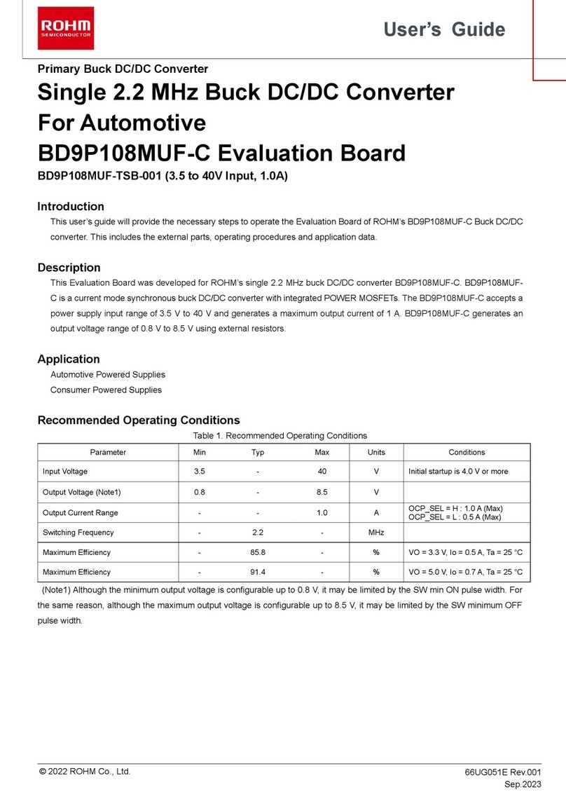
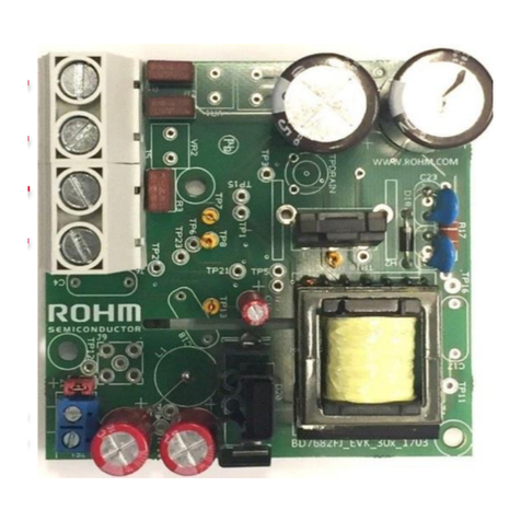
Rohm BD7682FJ-EVK-301 User manual

Rohm

Rohm BD7682FJ-EVK-301 User manual

Rohm REFLED005-EVK-002 User manual

Rohm

Rohm REFLED005-EVK-002 User manual

Rohm BD71805MWV Guide

Rohm

Rohm BD71805MWV Guide

Rohm BU1570KN Specification sheet

Rohm

Rohm BU1570KN Specification sheet

Rohm BD9P208MUF-TSB-001 User manual

Rohm

Rohm BD9P208MUF-TSB-001 User manual

Rohm PMIC BD96801 User manual

Rohm

Rohm PMIC BD96801 User manual

Rohm LAPIS Semiconductor ML62Q1739 User manual

Rohm

Rohm LAPIS Semiconductor ML62Q1739 User manual

Rohm LAPIS Semiconductor ML7404 Series Guide

Rohm

Rohm LAPIS Semiconductor ML7404 Series Guide

Rohm BD9P108MUF-TSB-001 User manual

Rohm

Rohm BD9P108MUF-TSB-001 User manual

Rohm BD16950EFV-EVK-001 User manual

Rohm

Rohm BD16950EFV-EVK-001 User manual

Rohm LAPIS Semiconductor ML22660 User manual

Rohm

Rohm LAPIS Semiconductor ML22660 User manual

Popular Computer Hardware manuals by other brands

Cooler Master RR-AM4B-H212-R1 quick start guide

Cooler Master

Cooler Master RR-AM4B-H212-R1 quick start guide

ENJOY GODFATHER user guide

ENJOY

ENJOY GODFATHER user guide

Intel E7500 user manual

Intel

Intel E7500 user manual

Fujitsu 467 manual

Fujitsu

Fujitsu 467 manual

NEC N8154-20 user guide

NEC

NEC N8154-20 user guide

Art FX-1 user guide

Art

Art FX-1 user guide

Epson S1C88 Series manual

Epson

Epson S1C88 Series manual

Cypress Semiconductor CY7C1241V18 Specification sheet

Cypress Semiconductor

Cypress Semiconductor CY7C1241V18 Specification sheet

National Instruments PXIe-8240 Getting started

National Instruments

National Instruments PXIe-8240 Getting started

Alphacool Eisblock Aurora Acryl RTX 4080 Strix with... manual

Alphacool

Alphacool Eisblock Aurora Acryl RTX 4080 Strix with... manual

Ralink RT3090 user manual

Ralink

Ralink RT3090 user manual

E-peas AEM00940 quick start guide

E-peas

E-peas AEM00940 quick start guide

OLIMEX SAM3-P256 user manual

OLIMEX

OLIMEX SAM3-P256 user manual

EK Quantum Magnitude sTRX5 user guide

EK

EK Quantum Magnitude sTRX5 user guide

NETGEAR WG511T installation guide

NETGEAR

NETGEAR WG511T installation guide

TYAN TS75-B7122 Service engineer's manual

TYAN

TYAN TS75-B7122 Service engineer's manual

Texas Instruments MSP-FET430X110 user guide

Texas Instruments

Texas Instruments MSP-FET430X110 user guide

AMD Athlon user manual

AMD

AMD Athlon user manual

manuals.online logo
manuals.online logoBrands
  • About & Mission
  • Contact us
  • Privacy Policy
  • Terms and Conditions

Copyright 2025 Manuals.Online. All Rights Reserved.