manuals.online logo
Brands
  1. Home
  2. •
  3. Brands
  4. •
  5. Roland
  6. •
  7. Power Tools
  8. •
  9. Roland RML-1 Instruction Manual

Roland RML-1 Instruction Manual

RML-1 PROGRAMING GUIDELINE
- 1 -
RML-1
PROGRAMING GUIDELINE
Ver䇭
䇭䇭
䇭1.00䇭䇭
䇭䇭䇭䇭
䇭䇭28,MAY,2002
䇭
RML-1 PROGRAMING GUIDELINE
- 2 -
INDEX
1 ; Overview of RML-1
2 ; Command Format
䇭
䇭䇭
䇭3 ; Descriptions of Commands
䇭
䇭䇭
䇭3-1;Mode –1
䇭䇭
䇭䇭䇭䇭
䇭䇭 3-2;Mode –2
䇭䇭
䇭䇭䇭䇭
䇭䇭 3-3;Commands Common to Mode-1 and Mode-2
4 ; Device Control Commands
䇭
䇭䇭
䇭4-1䋻
䋻䋻
䋻Format of Device Control Commands
4-2䋻
䋻䋻
䋻Descriptions of Device Control Commands
䇭䇭䇭
䇭䇭䇭䇭䇭䇭
䇭䇭䇭 ESCK Commands
䇭䇭䇭
䇭䇭䇭䇭䇭䇭
䇭䇭䇭 Other Device Control Commands
䇭
䇭䇭
䇭5 ; Appendix
5-1;Three-dimensional Movement
5-2䋻
䋻䋻
䋻Spindle motor
5-3䋻
䋻䋻
䋻Effects of Certain Commands on Other Commands
RML-1 PROGRAMING GUIDELINE
- 3 -
1;Overview of RML-1
1-1;Command Set
RML-1 commands are grouped as commands for mode 1, commands for mode 2, and
commands that are common to both mode 1 and mode 2.
Mode 1:Composed of one letter or symbol; based on DXY-GL.
Mode 2:Composed of two letters; based on RD-GL.
Common to mode 1 and mode 2: Composed of an "!" plus two letters.
For all three, the unit of measurement for the coordinate system is 1/100 mm.
Character codes are composed of 8-bit ASCII codes. valid letter, numerals, and symbols are
0x7f and lower. A code of 0x80 or higher results in an error even if the letter produced when
the eight bit (MSB) is zeroed is a valid command. When the communication parameters are
set for 7-bit sending, the data is converted to 8 bits, with the MSB assumed to be zero.
1-2;Supported RML Commands
Mode 1 D
F
H
I
M
R
V
W
Z
@
^
Mode 2 DF
IN
PA
PD
PR
PU
VS
Common to mode 1 and mode 2
!DW
!MC
!NR
!PZ
!RC
!VZ
!ZM
!ZO
!ZZ
!ZE
RML-1 PROGRAMING GUIDELINE
- 4 -
2;Command Format
2-1;Description
Commands are made up of letters and some symbols, and parameters are or a combination
of the two. Parameters are made up of numerals, which may be signed. Commands and
parameters are separated by delimiters and terminators.
Also, commands and parameters are eight bits, and have significance as character strings
when the most significant bit is zero. When this is not zero, the character string is neither a
command nor a parameter.
Each of these is described below.
2-2;Format for Mode 1
Format example * D ** 5000 ** [,] ** 5000 ** [terminator]
[Delimiter]
"*" indicates a character whose ASCII code is for the space or lower, or the ";"
character. One or more may be used, without restriction.
"**" indicates either the space or the tab character. One or more may be used,
without restriction.
[,] indicates the "," (comma) character. Only one may be used.
[Command]
The location shown by "D" is the command. It appears as a single letter or,
depending on the model, as "@", "!", "^", or "_". If D is preceded by a numeral or by
"+", "-", or ".", it is read and discarded with error 2. All other characters at 0x20 or
lower, and ";", are ignored.
When a single letter is recognized, a case-insensitive comparison is performed
against the list of valid commands for the model, and if the character string does not
match it is discarded with error 1. If a match is made, the corresponding command
is executed. Get parameters as required.
[Parameter]
The location shown by "5000" is the parameter. [,] is used as the delimiter for
parameters. Details are similar to parameters for mode 2.
[Terminator]
This is formally "CR + LF".
Unless specially noted otherwise, this can be omitted when followed by the next
command.
RML-1 PROGRAMING GUIDELINE
- 5 -
Special conditions are described in section 2-5.
2-3;Format for Mode 2
Format example * P ** A ** 5000 ** [,] ** 5000 ** [terminator]
[Delimiter]
"*" indicates a character whose ASCII code is for the space or lower, or the ";"
character. One or more may be used, without restriction.
"**" indicates either the space or the tab character. One or more may be used,
without restriction.
[,] indicates the "," (comma) character. Only one may be used.
[Command]
PA is the command, and is shown by two letters.
Only a space or tab may validly appear between the P and the A. There is no
restriction as to the number of space or tab characters. If a character other than
space or tab is used, it is read and discarded it with error 1. If P is preceded by a
numeral or by "+", "-", or ".", it is read and discarded with error 2. All other characters
at 0x20 or lower, and ";", are ignored.
When composed of two letters separated by a delimiter, a case-insensitive
comparison is performed against the list of valid commands for the model, and if the
character string does not match it is discarded with error 1. If a match is made, the
corresponding command is executed. Get parameters as required.
[Parameter]
This is a numeral and "+", "-", or ".". The characters that appear are not RML-1
commands.
The "+" may be omitted. The value "5000" must follow without any intervening extra
characters. If a character other than a numeral or "+", "-", and "." appears, the
character string up to that point is taken to be a single parameter.
A parameter has no E expression. They are composed only of numerals and ".", "+",
and "-". A parameter that is larger or smaller than the expected value results in error
3. Except for portions such as PU/PD that have already been executed, this portion
of the parameter is not executed.
(Valid numerical ranges of parameters:)
int type This indicates a range of -32768 to 32767. A size of two bytes is
ssumed.
long type This indicates a range of -8388608 to 8388607. A size of four
bytes is assumed.
RML-1 PROGRAMING GUIDELINE
- 6 -
float type This indicates a range of -8388608.0 to 8388607.0. A size of four
bytes and IEEE format are assumed.
Special conditions are described in section 2-5.
[Terminator]
This is ";". The [terminator] is formally ";".
Unless specially noted otherwise, this can be omitted when followed by the next
command.
It is required if not followed by the next command.
Special conditions are described in section 2-5.
2-4;Format for Commands Common to Mode 1 and Mode 2
Format example * ! ** P ** Z ** -200 ** [,] ** 100 ** [terminator]
[Delimiter]
"*" indicates a space or lower, or the ";" character. One or more may be used,
without restriction.
"**" indicates either the space or the tab character. One or more may be used,
without restriction.
[,] indicates the "," (comma) character.Only one may be used.
[Command]
Except for the addition of "!", the system is similar to mode 2.
If the "!" is preceded by a numeral or by "+", "-", or ".", it is read and discarded with
error 2.
All other characters at 0x20 or lower, and ";", are ignored.
When "!" is detected, interpretation of the following letter follows the rules for mode
2 commands, so refer to the description of mode 2 commands for the P and Z
portions.
[Parameter]
This is similar to the parameters for mode 2.
[Terminator]
The [terminator] is formally "CR + LF" for mode 1 and ";" for mode2.
Unless specially noted otherwise, this can be omitted when
followed by the next command.
2-5;Specific Examples of Special Cases Not Described Above
When a parameter contains a special character, and a "+", "-", "." (period), or
numeric string in a parameter string delimited by a command character and a
RML-1 PROGRAMING GUIDELINE
- 7 -
delimiter or terminator loses its significance as a numerical value, the
character is treated as a terminator.
(Examples)
PA100,,100; is equivalent to PA100,;,100;
PA100++100; is equivalent to PA100;++100;
PA100..100; is equivalent to PA100.;.100;
PA100,.100.0; is equivalent to PA100,0.100;.0;
PA 100 . 0, 100; is equivalent to PA100,0;0,100;
PA - 100, 100; is equivalent to PA-;100,100;
PA . 100, 100; is equivalent to PA0;100,100;
PD, is equivalent to PD;,
PD$ is equivalent to PD;$
PD< is equivalent to PD;<
PD^C is equivalent to PD;^C
PD[TAB]0,1; is equivalent to PD0,1;
PD-[CR]0,1; is equivalent to PD-;0,1;
When getting parameters, only the number of parameters that could be
obtained completely and correctly is executed.
(Specifically, cases resulting in an error are excluded.)
IP-; is executed with zero parameters.
IP 100,-; is executed with one parameter.
IP 100,100,-; is executed with two parameters.
IP 100,100,200,-; is executed with three parameters.
IP 100,100,200,200; is executed with four parameters.
IP 100,100,200,200,300; is executed with four parameters. Only the required
parameters are obtained. The final ",300" is passed to
the next command search.
PD-; is executed with zero parameters.
PD 100,-; is executed with one parameter.
Also, if the value of a parameter is out of range for its type (such as int), it is limited
to the type's maximum or minimum value.
In command processing, two letters must be obtained for mode 2 commands and
RML-1 PROGRAMING GUIDELINE
- 8 -
common commands. Even when the portion is only one letter and the determination
is made that there is no corresponding command, it is necessary to get one more
letter.
3;Descriptions of Commands
3-1;Mode 1
@ (Input Z1 & Z2 command)
<Format>
@ z1 (, z2) [terminator]
<Parameter type>
z1: long
z2: long
<Parameter range>
z1: Negative Z-axis operating range to 0
z2: 0 䌾8388607
<Description>
This sets point Z1,Z2 in the workpiece coordinate system.
Z1,Z2 specify a relative value from Z0 in the workpiece coordinate system.
When Z2 is not specified, the value already in effect is reused.
When no parameter exists, the value set using the operation panel may be
used, although this varies according to the model.
If either Z1 or Z2 (but not both) generates an error, the setting is made for
the value that did not generate an error.
<Errors>
Error3 results if Z1 is higher than zero or if Z2 is less than zero.
Error 3 similarly results when Z1 is outside the work area.
No error results when Z2 is outside the work area.
<Other Matters>
When Z2 is outside the work area, no error is generated and the setting is
made, but actual Z2 operation stop at the topmost location. (This is
because movement is physically impossible.)
D (Draw -- Line-cutting command)
<Format>
D x1, y1, x2, y2,..., xn, yn [terminator]
RML-1 PROGRAMING GUIDELINE
- 9 -
D [terminator]
<Type>
xn: float
yn: float
<Parameter Range>
-8388608.0 䌾8388607.0
<Description>
This sequentially cuts line segments between coordinates specified from
the present tool location, in the sequence x1,y1, x2,y2,..., xn,yn. The
coordinate values are all absolute coordinates. Thereafter the system is in
the absolute-coordinate mode.
<Errors>
For the parameters, a pair of values, x and y, constitute a single set, and
more than one set may be stated.
When the number of parameters is odd, each pair is sequentially
interpreted from the beginning as x and y and is executed accordingly, and
the final remaining odd value generates error 2. Execution is not
performed.
I (Relative draw -- Relative-coordinate line-cutting command)
<Format>
I dx1, dy1, dx2, dy2,..., dxn, dyn[terminator]
I [terminator]
<Type>
float
<Parameter Range>
-8388608.0 䌾8388607.0
<Description>
This performs cutting at the Z1 height from the present tool position to the
coordinates specified by the amount of change along the X axis dx1 and
the amount of change along the Y axis dy1. It next performs cutting at the
Z1 height from the position moved to, to the coordinates specified by the
amounts of change dy1, dy2 for the corresponding X and Y axes. This
sequentially performs cutting up through the final specified coordinates.
This cuts line segments between coordinates.
The coordinate values are all relative coordinates, and the system goes
into the relative-coordinate mode.
RML-1 PROGRAMING GUIDELINE
- 10 -
When the machine is at a height other than Z1 when first moving to the
amounts of change dx1, dy1, the spindle is rotated if it is in a rotatable
state, and after rotation stabilizes, movement to the Z1 height is effected at
the speed specified by !VZ or V. Thereafter movement to the coordinates
specified by dx1, dy1 is effected.
In cases where this command appears when the height is already at Z1,
the spindle is rotated if it is in a rotatable state, and after rotation stabilizes,
movement directly to the coordinates specified by dx1, dy1 is effected.
<Errors>
For the parameters, a pair of values, x and y, constitute a single set, and
more than one set may be stated.
When the number of parameters is odd, each pair is sequentially
interpreted from the beginning as x and y and is executed accordingly, and
the final remaining odd value generates error 2.Execution is not
performed.
M(Move -- Linear-movement command)
<Format>
M x1, y1, x2, y2,..., xn, yn [terminator]
M [terminator]
<Type>
float
<ParameterRange>
-8388608.0 䌾8388607.0
<Description>
This sequentially moves linearly at the Z2 height between coordinates
specified from the present tool location, in the sequence x1,y1, x2,y2,...,
xn,yn.
The coordinate values are all absolute coordinates, and the system goes
into the absolute-coordinate mode.
<Errors>
For the parameters, a pair of values, x and y, constitute a single set, and
more than one set may be stated.
When the number of parameters is odd, each pair is sequentially
interpreted from the beginning as x and y and is executed accordingly, and
the final remaining odd value generates error 2. Execution is not
performed.
RML-1 PROGRAMING GUIDELINE
- 11 -
R(Relative move -- Relative-coordinate linear-movement command)
<Format>
R dx1, dy1, dx2, dy2,..., dxn, dyn [terminator]
R [terminator]
<Type>
float
<Parameter Range>
-8388608.0 䌾8388607.0
<Description>
This performs movement at the Z2 height from the present tool position to
the coordinates specified by the amount of change along the X axis dx1
and the amount of change along the Y axis dy1.
It next performs movement at the Z2 height from the position moved to, to
the coordinates specified by the amounts of change dy1, dy2 for the
corresponding X and Y axes. This sequentially performs movement up
through the final specified coordinates.
It performs linear movement between the coordinates.
Movement is generally at the highest speed of the particular model.
The coordinate values are all relative coordinates, and the system goes
into the relative-coordinate mode.
When the machine is at a height other than Z2 when first moving to the
amounts of change dx1, dy1, the spindle is rotated if it is in a rotatable
state, and after rotation stabilizes, movement to the Z2 height is effected at
the speed specified by !VZ or V.
Thereafter movement to the coordinates specified by dx1, dy1 is effected.
In cases where this command appears when the height is already at Z2,
the spindle is rotated if it is in a rotatable state, and after rotation stabilizes,
movement directly to the coordinates specified by dx1, dy1 is effected.
<Errors>
For the parameters, a pair of values, x and y, constitute a single set, and
more than one set may be stated.
When the number of parameters is odd, each pair is sequentially
interpreted from the beginning as x and y and is executed accordingly, and
the final remaining odd value generates error 2. Execution is not
RML-1 PROGRAMING GUIDELINE
- 12 -
performed.
^(Call mode 2 -- Command for calling a mode 2 command)
<Format>
^ [mode 2 command] [parameter]...[parameter] [terminator(;)]
<Parameter Range>
This depends on the mode 2 command set.
<Description>
This calls a mode 2 command from mode 1.
For parameters, refer to the description for the called mode 2 command.
When only "^" is given, this instruction set does not end until a mode 2
command is executed or until a numeral, sign, or other such data that
results in a mode 2 error is encountered.
<Errors>
This command itself does not generate any errors.
Generation of an error by the mode 2 command is possible.
Also, if the called mode 2 command does not exist, then in principle error 2
for mode 2 is generated at that time.
H(Home -- Origin-movement command)
<Format>
H [terminator]
<Description>
This moves the tool to the uppermost position, then moves to the
workpiece-coordinate origin point on the XY plane. It then stops the
spindle motor.
If the workpiece-coordinate origin point is outside the cutting range, then
this moves, for example, to the clip location.
-> Command errors are cleared.
-> After the operation, the settings for tool-up, absolute-
coordinate mode, and coordinate values are reset.
The present position of the tool is the same as the position in the
workpiece coordinate system.
<Errors>
No error is generated.
<Other Matters>
RML-1 PROGRAMING GUIDELINE
- 13 -
There is no change before and after command execution in the XY origin
point or in the value of Z0 set using the control panel.
F (Velocity XY axis -- X- and Y-direction speed setting command)
<Format>
F tool-speed [terminator]
F [terminator]
<Type>
Basically int
float for noninteger values such as F 0.5
<Parameter Range>
-32768 䌾32767 [mm/sec]
<Description>
F without a parameter is set to the default speed.
When a parameter is present and is a settable speed, the speed is set to
the value of the parameter.
When the value of the parameter is the model's capacity or higher, the
model's Maximum speed is used.
When the value of the parameter is the model's capacity or lower, the
model's minimum speed is used.
In operation, achieving the actual given parameter value cannot be
guaranteed.
Depending on the length of the line segment, operation may be slower
than the value specified by the parameter because of an inability to
accelerate fully.
Also, even when full acceleration is possible, the specified speed may not
necessarily be accurately reached; precision may be low.
Examples for some models:
F 0 may be 0.5 mm/sec.
F 0.1 to F 1.0 may be in increments of 0.1 mm/sec.
Values of F 1.0 or higher may be in increments of 1 mm/sec.
The default value may be, for example, 2 mm/sec.
<Errors>
No error is generated.
<Other Matters>
RML-1 PROGRAMING GUIDELINE
- 14 -
Similar to VS.
V(Velocity Z axis -- Tool up/down speed setting command)
<Format>
V tool-up/down speed [terminator]
V [terminator]
<Type>
Basically int
float for noninteger values such as V 0.5
<Parameter Range>
-32768 䌾32767 [mm/sec]
<Description>
This sets the speed relationship when the tool moves along the Z axis or
when movement is performed using the three-axis simultaneous-
movement command.
V without a parameter is set to the default speed.
When a parameter is present and is a settable speed, the speed is set to
the value of the parameter.
When the parameter is not a settable value, the maximum or minimum
settable value is set automatically.
<Errors>
An out-of-range parameter results in error 3.
When the parameter is within range, no error occurs even if its value
cannot be set on the particular model.
W (dwell -- Dwell specification command)
<Format>
W dwell-time [terminator]
W [terminator]
<Type>
int
<Parameter Range>
0 to 32,767 msec
<Description>
When a parameter is given, if it is a settable value, then dwell (waiting) for
the time set by the value is performed when the cutting direction changes.
RML-1 PROGRAMING GUIDELINE
- 15 -
When W is used without a parameter, the default value is applied (0
msec).
There is no wait time when the direction of cutting changes.
When a two-dimensional command such as PD or PU is used, the dwell
operation is performed just before the PD tool-down operation or just
before moving the XY plane period parameters.
It is also performed just before changing from tool-down to tool-up with
PU.
However, it is not performed when a PU parameter manipulates the XY
plane.
In the case of a PU or PD command without parameters, it is performed
just before the tool-up or tool-down operation.
In the case of a three-dimensional movement command such as !ZZ, it is
performed just before the operation of that command is carried out.
Operations other than the command's are unaffected.
<Errors>
A value less than 0 or over 32767 results in error 3.
<Other Matters>
Z (XYZ move -- Three-axis simultaneous feed command)
<Format>
Z x1,y1,z1,... [terminator]
<Type>
float
<Parameter Range>
-8388608.0 䌾8388607.0
<Description>
This moves simultaneously along the three axes from the present
coordinates to the specified coordinate values.
The speed is as set by the V or !VZ command.
When no parameter is present, no operation is performed.
Additionally, the parameters are interpreted as absolute coordinates when
set to absolute coordinates prior to this command and are interpreted as
relative values when set to relative coordinates prior to this command.
RML-1 PROGRAMING GUIDELINE
- 16 -
<Errors>
For the parameters, three values -- x, y, and z -- make up one set, and
more than one set may be stated.
When the number of parameters is not a multiple of three, the parameters
are interpreted and executed in sequence from the start as x, y, and z, and
the final one or final two results in error 2. The final set is not executed.
<Other Matters>
Common with !ZZ.
<For Reference>
V, !VZ, ! ZZ
3-2;Mode 2
DF (Default – Default-setting command)
<Format>
DF [terminator]
<Description>
This sets some present settings to their standard values.
1. PA This is set to absolute coordinates.
2. VS Speed is set to the default value.
Theactualvalueismodel-dependent.
3. !VZ Speed is set to the default value.
The actual value is model-dependent.
4. !DW Dwell time is set to 0.
5. !MC Rotation is permitted.
6. !PZ The value is initialized. The actual value varies
according to the model.
<Errors>
No error is generated.
IN (Initialize -- Initialize-setting command)
<Format>
IN [terminator]
<Description>
This performs the same operations as the standard settings made by the
DF command, as well as making the following settings.
RML-1 PROGRAMING GUIDELINE
- 17 -
1. Move the tool to the tool-up position.
2. PU.
3. Clear errors.
4. Stop the spindle motor.
5. Reset the coordinate values. The present position of the tool is the
same as the position in the workpiece coordinate system.
<Errors>
No errors.
<Other Matters>
There is no change before and after command execution in the XY origin
point or in the value of Z0 set using the control panel.
PA (Plot Absolute -- Absolute plot command)
<Format>
PA x1, y1, (, x2, y2,....) [terminator]
PA [terminator]
<Type>
x: float
y: float
<Parameter Range>
x: -8388608.0 to 8388607.0
y: -8388608.0 to 8388607.0
<Description>
A PA command without parameters effects a change to the absolute-
coordinate mode.
When parameters are present, the command effects the absolute-
coordinate mode and performs operation for the coordinate values
specified by the parameters, without change the present state of the tool
(up or down).
<Errors>
For the parameters, a pair of values, x and y, constitute a single set, and
more than one set may be stated.
When the number of parameters is odd, each pair is sequentially
interpreted from the beginning as x and y and is executed accordingly, and
the final remaining odd value generates error 2. Execution is not
performed.
RML-1 PROGRAMING GUIDELINE
- 18 -
<Other Matters>
PU/PD (Pen Up/Down -- Tool up/down command)
<Format>
PU x1, y1, (, x2, y2,....) [terminator]
PU [terminator]
PD x1, y1, (, x2, y2,....) [terminator]
PD [terminator]
<Type>
x: float
y: float
<Parameter Range>
x: -8388608.0 to 8388607.0
y: -8388608.0 to 8388607.0
<Description>
PU or PD without parameters performs only a tool-up or tool-down
operation.
When parameters are present, the command performs the tool-up or
tool-down operation, then operates to the coordinate value specified by
the parameters.
The parameters used for operation are absolute coordinates when a PA
command has previously been given or relative coordinates when a PR
command has previously been given.
The up or down position uses the height specified using the control panel
or the !PZ or @ command.
The tool-up location is the Z2 location.
The tool-down location is the Z1 location.
When Z2 is outside the cutting range, the tool rises to the maximum height
at which the device can operate.
If X and Y movement is necessary thereafter, the movement is performed
at the maximum height.
If a PD command appears thereafter, there is no pause when moving from
outside to inside the clipping area, even if such a setting has been made.
Operation is performed without change.
RML-1 PROGRAMING GUIDELINE
- 19 -
Because Z1 cannot be set outside the device's cutting range, movement
to the set value is performed.
The operating speed for the PD command is set using the VS or F
command.
However, the speed specified by the VS or F command may not
necessarily be reached. Depending on the length of the line segment for
the operation, a slower speed than specified may be set automatically.
The specified speed is reached when the line segment is long enough to
allow sufficient acceleration.
PU operates at a particular specified speed, regardless of the VS
command.
This ordinarily the model's highest speed, but it may be set at a lower
value in some cases.
The specified speed is of course reached when the line segment is of the
required length for acceleration, but in cases where sufficient acceleration
is not possible, a slower speed is automatically used.
<Errors>
For the parameters, a pair of values, x and y, constitute a single set, and
more than one set may be stated.
When the number of parameters is odd, each pair is sequentially
interpreted from the beginning as x and y and is executed accordingly, and
the final remaining odd value generates error 2. Execution is not
performed.
<Other Matters>
Z2 can be set outside the cutting range, and its value is retained.
If Z0 is lowered so that Z2 comes within the effective range, its value is
used.
PR (Plot Relative -- Relative plot command)
<Format>
PR x1, y1, (, x2, y2,....) [terminator]
PR [terminator]
<Type>
RML-1 PROGRAMING GUIDELINE
- 20 -
x: float
y: float
<Parameter range>
x: -8388608.0 to 8388607.0
y: -8388608.0 to 8388607.0
<Description>
A PR command without parameters effects a change to the relative-
coordinate mode.
When parameters are present, the command effects the relative-
coordinate mode and performs operation for the coordinate values
specified by the parameters, without change the present state of the tool
(up or down).
<Errors>
For the parameters, a pair of values, x and y, constitute a single set, and
more than one set may be stated.
When the number of parameters is odd, each pair is sequentially
interpreted from the beginning as x and y and is executed accordingly, and
the final remaining odd value generates error 2. Execution is not
performed.
<Other Matters>
VS (velocity select -- Tool-speed setting command)
<Format>
VS tool-speed [terminator]
VS [terminator]
<Type>
Basically int
float for noninteger values such as vs 0.5
<Parameter Range>
-32768 to 32767 [mm/sec]
<Description>
VS without a parameter is set to the default speed.
When a parameter is present and is a settable speed, the speed is set to
the value of the parameter.
When the value of the parameter is the model's capacity or higher, the
model's maximum speed is used.

Other Roland Power Tools manuals

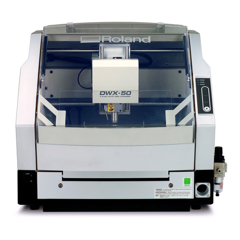
Roland DWX-50 Operating manual

Roland

Roland DWX-50 Operating manual

Roland PNC-3100 CAMM-3 User manual

Roland

Roland PNC-3100 CAMM-3 User manual
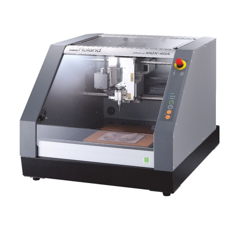
Roland MDX-40A User manual

Roland

Roland MDX-40A User manual

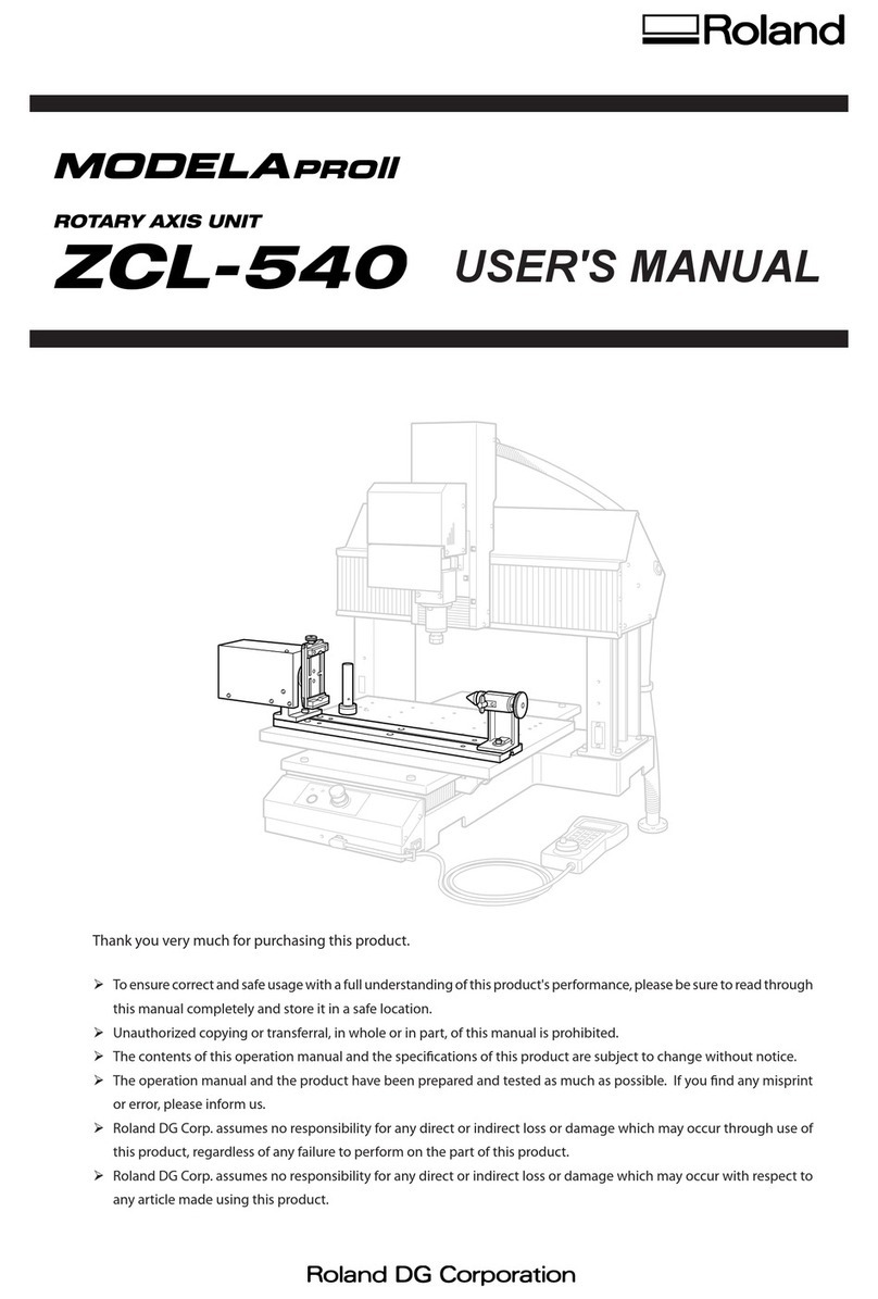
Roland MODELA Pro II ZCL-540 User manual

Roland

Roland MODELA Pro II ZCL-540 User manual

Roland MODELA MDX-50 User manual

Roland

Roland MODELA MDX-50 User manual

Roland CAMM-3 PNC-3200 User manual

Roland

Roland CAMM-3 PNC-3200 User manual

Roland MODELA Pro ZCL-650A User manual

Roland

Roland MODELA Pro ZCL-650A User manual

Roland DWX-51D User manual

Roland

Roland DWX-51D User manual

Roland MODELA PRO II series Use and care manual

Roland

Roland MODELA PRO II series Use and care manual

Roland monoFab SRM-20 User manual

Roland

Roland monoFab SRM-20 User manual

Roland ZAT-540 User manual

Roland

Roland ZAT-540 User manual

Roland iModela iM-01 User manual

Roland

Roland iModela iM-01 User manual

Roland monoFab SRM-20 User manual

Roland

Roland monoFab SRM-20 User manual

Roland DWX-51D User manual

Roland

Roland DWX-51D User manual
Roland CAMM-3 PNC-3200 Operating and maintenance manual

Roland

Roland CAMM-3 PNC-3200 Operating and maintenance manual

Roland CAMM-3 PNC-300 User manual

Roland

Roland CAMM-3 PNC-300 User manual

Roland MODELA Pro MDX-650A User manual
Roland

Roland MODELA Pro MDX-650A User manual

Roland CAMM-3 PNC-3200 User manual

Roland

Roland CAMM-3 PNC-3200 User manual
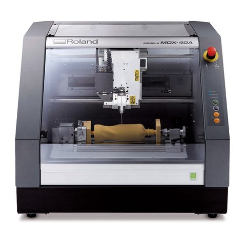
Roland MDX-40A User manual

Roland

Roland MDX-40A User manual

Popular Power Tools manuals by other brands

Skil 96VXT Operating/safety instructions

Skil

Skil 96VXT Operating/safety instructions

Mannesmann Demag RRI-50T operating manual

Mannesmann Demag

Mannesmann Demag RRI-50T operating manual

Lamello Minispot G2A operating instructions

Lamello

Lamello Minispot G2A operating instructions

Bosch GSR 18 V Original instructions

Bosch

Bosch GSR 18 V Original instructions

Milescraft Plunger 1000 quick start guide

Milescraft

Milescraft Plunger 1000 quick start guide

Sioux Tools TP9A Series Instructions-parts list

Sioux Tools

Sioux Tools TP9A Series Instructions-parts list

Makita DF330D instruction manual

Makita

Makita DF330D instruction manual

Milwaukee M18 BI manual

Milwaukee

Milwaukee M18 BI manual

Drill Master 67042 Set up and operating instructions

Drill Master

Drill Master 67042 Set up and operating instructions

stayer VAC L 18 operating instructions

stayer

stayer VAC L 18 operating instructions

Northem 999360 owner's manual

Northem

Northem 999360 owner's manual

Hitachi H 60MR Handling instructions

Hitachi

Hitachi H 60MR Handling instructions

AEG SE 2.4 Instructions for use

AEG

AEG SE 2.4 Instructions for use

Yokota TKA90 manual

Yokota

Yokota TKA90 manual

MQ Multiquip MVC82VHW Operation and parts manual

MQ Multiquip

MQ Multiquip MVC82VHW Operation and parts manual

SUHNER LBC 16-TOP Technical document

SUHNER

SUHNER LBC 16-TOP Technical document

Westfalia 84 55 16 instruction manual

Westfalia

Westfalia 84 55 16 instruction manual

Komet HSK Series operating instructions

Komet

Komet HSK Series operating instructions

manuals.online logo
manuals.online logoBrands
  • About & Mission
  • Contact us
  • Privacy Policy
  • Terms and Conditions

Copyright 2025 Manuals.Online. All Rights Reserved.