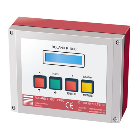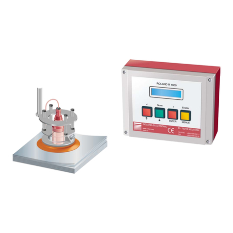
Manual
Double Sheet Detector R100-Serie A100
for single sided sensors
B0003306 / Rev. 1.0
04.07.2008 Table of Contents
ROLAND ELECTRONIC GmbH · Otto-Maurer-Str. 17 · DE 75210 Keltern · Phone +49 (0)7236-9392-0 · Fax +49 (0)7236-9392-33 3
Declaration of conformity according to EC directives ................................................................................... 5
1Safety advices .......................................................................................................................................7
1.1 General ........................................................................................................................................... 7
1.2 Safety instructions and warnings for user .......................................................................................7
2System description...............................................................................................................................9
2.1 Introduction ..................................................................................................................................... 9
2.2 Structure and measuring principle .................................................................................................. 9
2.3 Functional sequence..................................................................................................................... 10
3Technical data .....................................................................................................................................11
3.1 Control unit A100 .......................................................................................................................... 11
3.2 T sensors ...................................................................................................................................... 13
3.2.1 Sensor T04 ............................................................................................................................... 13
3.2.2 Sensor T08 / T08S.................................................................................................................... 13
3.2.3 Sensor T15 / T15S.................................................................................................................... 13
3.2.4 Sensor T30 / T30S.................................................................................................................... 13
3.2.5 Sensor T40 / T40S.................................................................................................................... 13
3.2.6 Technical drawing T sensors.................................................................................................... 14
3.2.7 Cable allocation of T-sensors and sensor cable KS ................................................................. 14
3.2.8 Cable allocation of sensor cable KTGS-G ................................................................................ 14
4Monunting............................................................................................................................................15
4.1 Mounting of the control unit........................................................................................................... 15
4.2 Mounting of the sensors................................................................................................................ 15
4.3 Cables........................................................................................................................................... 17
4.3.1 Sensor cables........................................................................................................................... 17
4.3.2 Power supply / Control cables .................................................................................................. 17
5Electrical installation ..........................................................................................................................19
5.1 Connecting diagram...................................................................................................................... 20
5.1.1 Connecting diagram for sensors T…GS via cable KTGS-G..................................................... 21
6Start-up ................................................................................................................................................23
6.1 Keys and indicators....................................................................................................................... 23
6.2 Allocation and function of keys ..................................................................................................... 24
6.3 Switching on and Powering up...................................................................................................... 24
6.4 Operational conditions .................................................................................................................. 25
6.4.1 Undisturbed operation .............................................................................................................. 25
6.4.2 Detection of 0-sheet, 1-sheet or 2-sheet .................................................................................. 25
