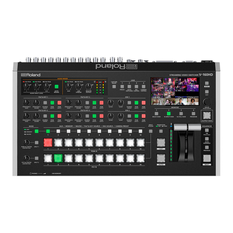
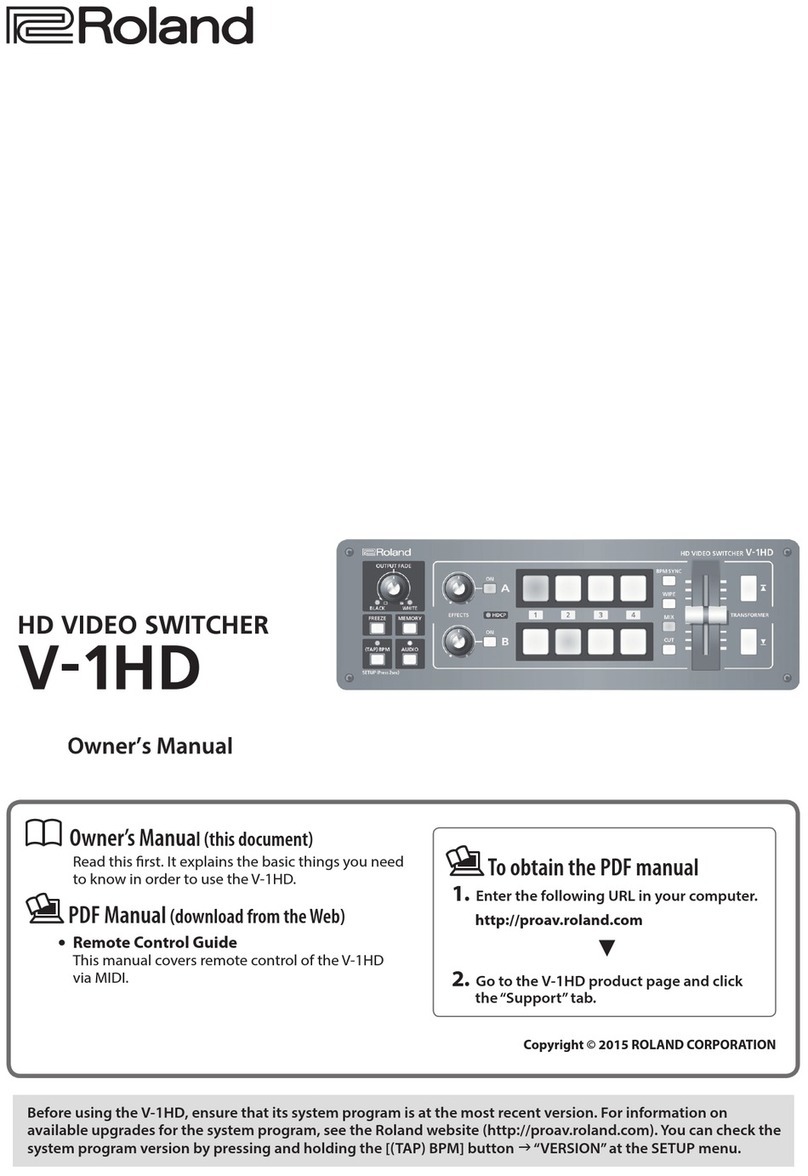
Roland V-160HD User manual

02
© 2021 Roland Corporation
Reference Manual

2
Contents
Panel Descriptions..................................... 4
ÄTop Panel ................................................ 4
ÄFront Panel .............................................. 6
ÄRear Panel ............................................... 7
ÄConnecting Bluetooth® Devices .......................... 8
ÄConnecting a Footswitch . . . . . . . . . . . . . . . . . . . . . . . . . . . . . . . . . 9
Basic Operations ....................................... 10
ÄTurning the Power On/O ................................ 10
ÄOperating the Menu ..................................... 10
ÄSwitching the Monitor View .............................. 11
Video Input/Output Settings......................... 12
ÄSetting the Video Input/Output Format . . . . . . . . . . . . . . . . . . . 12
Setting the System Format.................................. 12
Setting the Input Format for the HDMI IN 5–8 Connectors ...... 12
ÄAssigning Video Sources ................................. 13
ÄAdjusting Output Video .................................. 13
ÄAdjusting Input Video .................................... 14
ÄAssigning Video Buses to Output Connectors ............. 14
ÄSelecting the Video Sent to the AUX Bus .................. 15
ÄInputting Copy-Protected (HDCP) Video .................. 15
ÄSpecifying a Reference Clock ............................. 16
Video Operations ...................................... 17
ÄSwitching the Video...................................... 17
Setting the Operation Mode ................................ 17
Switching in the PGM/PST Mode ............................ 17
Switching in the A/B Mode ................................. 18
Changing the Mix/Wipe Pattern ............................. 19
Changing the Functions of the [CUT] and [AUTO] Buttons ...... 19
ÄSwitching the Video Automatically (Auto Switching)....... 20
About the Operation Mode ................................. 20
Turning the Auto Switching Function On/O.................. 20
Setting the Operation Mode ................................ 20
ÄLoading a Still Image..................................... 22
Loading a Still Image from a USB Flash Drive .................. 22
Capturing a Still Image from Input/Output Video .............. 23
Deleting a Still Image ...................................... 23
ÄSaving a Still Image to a USB Flash Drive .................. 24
ÄOutputting a Loaded Still Image.......................... 25
ÄFreezing the Input Video (Freeze) ......................... 25
ÄFading-In/Out the Final Output Video..................... 26
Video Composition Operations...................... 27
ÄCompositing Video with Split............................. 27
Conguring the Screen Layout .............................. 27
Compositing Using SPLIT ................................... 27
ÄCompositing Video with Picture-in-Picture (PinP).......... 28
Making Detailed Settings for the Inset Screen ................. 29
Key Compositing the Inset Screen ........................... 29
ÄCompositing Video with Downstream Keyer (DSK) ........ 30
About DSK Mode . . . . . . . . . . . . . . . . . . . . . . . . . . . . . . . . . . . . . . . . . . 30
Compositing a Caption or Image (Luminance Key)............. 31
Compositing a Subject and Background (Chroma Key) ......... 33
Compositing a Still Image with Alpha Channel ................ 35
Using an External Key ...................................... 36
Audio Operations ...................................... 37
ÄAdjusting the Input Gain (Sensitivity) ..................... 37
ÄAdjusting the Volume Balance............................ 38
ÄApplying Eects to Input Audio .......................... 39
Suppressing Echo in a Web Conference System (Echo Canceller) .. 40
Reducing Acoustic Feedback (Anti-Feedback) . . . . . . . . . . . . . . . . . 40
Changing the Character of a Voice (Voice Changer) ............ 41
Correcting a Time Dierence Between Video and Audio (Delay) ... 41
ÄApplying Eects to Output Audio......................... 42
ÄInterlinking Audio Output to Video Switching
(Audio Follow) ........................................... 43
ÄControlling the Volume Automatically (Auto Mixing) ...... 43
ÄChecking a Specic Audio Input (Solo) .................... 44
ÄSilencing Only Specic Audio (Mute)...................... 44
ÄOutputting AUX-bus Audio ............................... 45
ÄAdding Input Audio to an HDMI or SDI Video for Output... 46
Live Streaming ......................................... 47
ÄOutputting Video/Audio to a Computer for Streaming..... 47
Outputting Video and Audio to the Computer ................ 47
Using the Loopback Function ............................... 47
Other Functions ........................................ 48
ÄSaving/Recalling Settings (Preset Memory) ............... 48
Saving to a Preset Memory ................................. 48
Recalling a Preset Memory.................................. 48
Initializing a Preset Memory ................................ 49
Renaming a Preset Memory................................. 49
ÄRecording Multiple Operations to Automatically Execute
(Macros) ................................................. 50
Recording a Macro......................................... 50
Executing a Macro ......................................... 52
Copying Macro Settings .................................... 53
Swapping the Macro Settings ............................... 53
Initializing a Macro ........................................ 54
Renaming a Macro......................................... 54
Saving/Loading the Macro Settings .......................... 55
ÄCombining Preset Memories and Macros for Operations
(Sequencer).............................................. 57
Recording to the Sequencer ................................ 57
Running the Sequencer .................................... 59
Making the Sequencer Run Automatically (Auto Sequence)..... 60
Saving/Loading the Sequencer Settings ...................... 61
Initializing the Sequencer................................... 62
ÄBacking Up and Restoring the Unit’s Settings ............. 63
Backing Up ............................................... 63
Restoring................................................. 64
3
Contents
ÄFormatting a USB Flash Drive............................. 64
ÄAssigning Functions to the USER Buttons ................. 65
ÄControlling an External Recorder’s Video Record
Start/Stop from the V-160HD ............................. 65
ÄRemotely Controlling a PTZ Camera ...................... 66
Network Settings on the Camera ............................ 66
Registering Camera Settings in a Preset ...................... 66
Recalling a Preset.......................................... 67
ÄUsing a Footswitch....................................... 68
ÄUsing an Expression Pedal................................ 69
ÄControl Using the TALLY/GPIO Connector ................. 70
Specication of the TALLY/GPIO Connector ................... 70
Inputting a Control Signal .................................. 70
Outputting a Tally Signal ................................... 71
Outputting a Control Signal................................. 71
ÄUsing Smart Tally ........................................ 72
ÄPreventing Unintended Operation (Panel Lock) ........... 73
ÄReturning to the Factory Settings (Factory Reset).......... 73
ÄRemotely Controlling the V-160HD ....................... 74
Menu List................................................ 75
1: VIDEO ASSIGN ........................................... 75
2: VIDEO INPUT ............................................ 76
3: VIDEO OUTPUT .......................................... 77
4: TRANSITION TIME ........................................ 77
5: MIX/WIPE................................................ 78
6: SPLIT . . . . . . . . . . . . . . . . . . . . . . . . . . . . . . . . . . . . . . . . . . . . . . . . . . . . 78
7: PinP & KEY............................................... 79
8: DSK ..................................................... 81
9: AUDIO INPUT ............................................ 82
10: AUDIO OUTPUT......................................... 88
11: AUDIO FOLLOW ........................................ 90
12: AUDIO AUTO MIXING ................................... 90
13: PRESET MEMORY ....................................... 91
14: MACRO................................................. 92
15: SEQUENCER ............................................ 93
16: STILL IMAGE............................................ 93
17: FREEZE ................................................. 94
18: AUTO SWITCHING ...................................... 94
19: CTL/EXP ................................................ 95
20: RS-232/TALLY/GPO/GPI ................................. 97
21: LAN CONTROL.......................................... 98
22: CAMERA CONTROL ..................................... 99
23: USB MEMORY ..........................................100
24: SYSTEM ................................................100
ÄList of Shortcut Keys .....................................104
Appendix................................................105
ÄAbout Rack Mounting ....................................105
ÄMain Specications ......................................106
ÄDimensions..............................................109
ÄVideo Block Diagram .....................................110
ÄAudio Block Diagram.....................................111
¹The Bluetooth® word mark and logos are registered trademarks owned by Bluetooth SIG, Inc. and any use of such marks by Roland is under license.
¹QR Code is a registered trademark of DENSO WAVE INCORPORATED in Japan and in other countries.
¹Roland is an either registered trademark or trademark of Roland Corporation in the United States and/or other countries.
¹Company names and product names appearing in this document are registered trademarks or trademarks of their respective owners.

4
Panel Descriptions
Top Panel
1
AUDIO MIXER
SIG/PEAK indicators (1, 2, 3/4)
Shows the volume level for the AUDIO IN 1, 2, or 3/4.
Indicator Status
Red Volume is excessive (0 dB or higher)
Yellow Volume is appropriate (-20 – -1 dB).
Green Volume is insucient (-50– -21 dB).
AUDIO INPUT LEVEL [1] [2] [3/4] knobs
Adjust the volume of the AUDIO IN 1, 2, or 3/4.
[AUTO MIXING] button
Turns the auto-mixing function (used to automatically control the
volume) on/o.
SIG/PEAK indicators (AUX, USB STREAM)
Shows the volume level for the AUX bus and USB output.
[AUX] knob
Adjusts the volume of the AUX bus output.
[USB STREAM] knob
Adjusts the volume of the USB output.
[MASTER OUTPUT] knob
Adjusts the overall volume.
Level meter
Indicates the volume level of the overall output.
2
[CAPTURE IMAGE] button
Turns the still image capture mode on/o.
3
USER [1]–[4] buttons
These buttons execute pre-assigned functions.
With the factory settings, the following functions are assigned.
Button Explanation
USER [1] FREEZE
Turns the freeze function (freeze the input video) on/o.
USER [2]
AUTO SWITCHING
Turns the auto switching function (used to automatically
switch between videos) on/o.
USER [3]
REC CONTROL
Controls the recorder’s video record start/stop if a recorder
that supports REC control functionality is connected.
USER [4]
CAMERA CONTROL
Turns the camera control function on/o.
When this is on (lit), the
7
CAMERA PRESET [1]–[10]
buttons are used to recall the presets.
4
PinP & KEY 1–4
This uses PinP and KEY 1–4 layers to composite video using PinP,
or picture-in-picture (p. 28).
[POSITION H] knob
Adjusts the horizontal position of the inset screen.
By turning the knob while pressing it, you can adjusts the size of
the inset screen.
[POSITION V] knob
Adjusts the vertical position of the inset screen.
By turning the knob while pressing it, you can adjust the zoom of
the video shown in the inset screen.
[SOURCE] button
When this is on (lit), you can select the video source for the inset
screens using the
7
PinP & KEY SOURCE [1]–[10] buttons.
[PVW] button
Turns the inset screen preview output on/o.
[PGM] button
Turns PinP composition on/o.
2
11
12
15
13
16
17
19
20
21
22
10
3
1
4
5
6 7
8
9 14
18
23

5
Panel Descriptions
5
DSK 1, 2
This uses DSK layer 1 or 2 to composite video using a downstream
keyer (p. 30).
[LEVEL] knob
Adjusts the degree of extraction (transparency) for the key.
[GAIN] knob
Adjusts the degree of edge blur (semi-transmissive region) for the
key.
[SOURCE] button
When this is on (lit), you can select the DSK video source using the
7
PinP & KEY SOURCE [1]–[10] buttons.
[PVW] button
Turns the preview output of the DSK compositing result on/o.
[PGM] button
This switches DSK composition on or o.
6
[MODE] button
7
Switches the functioning of the AUX / MEMORY / MACRO [1]–
[10] buttons. An indicator located at the left of the [MODE] button
is lit to indicate the current function.
7
AUX / MEMORY / MACRO / PinP & KEY SOURCE /
DSK SOURCE / CAMERA PRESET [1]–[10] buttons
The functions of these buttons change as shown in the table
below.
When button is lit Functions of buttons [1]–[10]
[MODE]
AUX
Select the video that is sent to the AUX bus.
MEMORY
Recalls the preset memory (the video/audio
and other data that is saved). Long-press a
button to save the current settings in a preset
memory.
MACRO
Executes a macro (a series of recorded
operations).
PinP & KEY 1–4
[SOURCE]
PinP & KEY SOURCE
Select the video source for the inset screen (p.
28).
DSK 1, 2 [SOURCE] DSK SOURCE
Selects the DSK video source (p. 30).
USER [4]
(CAMERA CONTROL)
CAMERA PRESET
Recalls the registered preset (camera position,
focus settings, etc.) from the connected camera.
8
[PGM/A-CENTER] [PST/B-CENTER] knobs
Adjust the split compositing settings (p. 27).
Knob Explanation
[PGM/A-CENTER]
Adjusts the horizontal/vertical position of the
video that’s shown in the left or upper area.
Turn while pressing:
Adjusts the position of the boundary.
[PST/B-CENTER]
Adjusts the horizontal/vertical position of the
video that’s shown in the right or lower area.
Turn while pressing:
Adjusts the position of the boundary.
9
[SPLIT 1] [SPLIT 2] buttons
Turns on/o video compositing using split (p. 27).
10
PGM/A cross-point [1]–[10] buttons
Selects the video to input to bus PGM/A. The selected button
lights up.
11
PST/B cross-point [1]–[10] buttons
Selects the video to input to bus PST/B. The selected button lights
up.
12
[INPUT ASSIGN] button
Press a cross-point button while holding down the [INPUT ASSIGN]
button to change the video source for the buttons you pressed.
The video source changes in the following order each time you
press the button.
¹[INPUT ASSIGN] + PGM/A cross-point buttons
STILL 16 Ó1 ÓSDI 8 Ó1 ÓHDMI 8 Ó1
¹[INPUT ASSIGN] + PST/B cross-point buttons
HDMI 1
Ó8 ÓSDI 1
Ó8 ÓSTILL 1
Ó16
13
[TRANSITION] button
Selects the video transition eects (MIX, WIPE).
The MIX or WIPE indicator lights to show that it is selected.
14
[CUT] [AUTO] button
Automatically switch between the videos being input to bus
PGM/A and PST/B, and send them to the nal output.
Button Explanation
[CUT] The picture switches instantly.
[AUTO] A transition eect is applied and the video is switched
automatically.
15
(Bluetooth®) indicator
Shows the Bluetooth connection status.
Lit Connected Rapid blinking Now pairing
Unlit Bluetooth o Blinking Waiting for connection
You can input audio from an audio device that uses Bluetooth, or
use dedicated app on your computer or iPad to remotely control
the V-160HD.
16
Video fader
Manually switch between the videos being input to bus PGM/A
and PST/B, and send them to the nal output.
Transition indicator
The indicators light up to show the video fader position.
When the video fader is pushed all the way down, only the
topmost or bottommost transition indicator lights.
17
Monitor
Shows the input/output video, a loaded still image, or a menu.
* The same video as that shown on the monitor of this unit is output
from the HDMI OUT 3 connector.

6
Panel Descriptions
Front Panel
18
MONITOR [1]–[4] buttons
Switches between the video to monitor. Both the display from the
monitor of this unit and the output video from the HDMI OUT 3
connector switch at the same time.
Button Explanation
MONITOR [1]
MULTI-VIEW
The nal output video, preview output video and the
videos allocated to the cross-point [1]–[8] buttons
are shown in sections of the display.
MONITOR [2]
16 INPUT-VIEW
The input video from the HDMI IN connectors and
the SDI IN connectors are shown as 16 separate
sections on the screen.
MONITOR [3]
16 STILL-VIEW
Shows the loaded still images in 16 separate sections
on the screen.
MONITOR [4] PROGRAM
Shows the nal output video.
* The settings described above are the factory defaults. You can also
assign dierent video to each button.
19
[MENU] button
Switches the menu between visible and hidden.
The menu appears on the built-in monitor and the display
connected to the HDMI OUT 3 connector.
20
[EXIT] button
Returns you to the menu one level higher.
21
[VALUE] knob
Selects a menu item, or edits the value of a setting.
Press this knob to conrm the menu item you selected or the
value that you edited.
22
[OUTPUT FADE] button
The nal output video and audio fade in/out.
Lit Fade-out completed
Blinking Now fading-in/out
Unlit Normal output
23
SEQUENCER
Use this to execute operations such as macros or recalling preset
memories (sequencer function) in the order that you have
specied beforehand.
[ON] button
Long-press to turn sequencer function on/o.
[AUTO SEQUENCE] button
Turns the auto sequence function on/o.
[PREVIOUS] button
Returns to the previous operation.
[NEXT] button
Advances to the next operation. The button blinks while the
operation is executing.
1
PHONES jack
Connect headphones.
2
[PHONES] knob
Adjusts the volume of the headphones.
3
USB MEMORY port
Connect a USB ash drive. Use this to save/load the settings of this
unit, and to load/save still images.
* Never turn o the power or remove the USB ash drive while the USB
ash drive is being accessed.
1
2
3

7
Panel Descriptions
1
RS-232 connector
You can connect this to a computer equipped with an RS-232
connector, and remotely control the V-160HD.
2
TALLY/GPIO connector
Use this to connect to devices that have a tally indicator feature,
or to connect to devices that have a control signal input/output
function.
3
CTL/EXP 1, 2 jacks
Connect footswitches (sold separately: BOSS FS-6, etc.) or
expression pedals (sold separately: EV-5, etc.). This is used when
using your foot to control operations such as video switching.
* Use only the specied expression pedal (sold separately: EV-5, BOSS
FV-500L, or FV-500H). By connecting any other expression pedals, you
risk causing malfunction and/or damage to the unit.
4
REFERENCE THRU connector
Sends the synchronization signal that is inputted to the V-160HD
to an external device that is connected to this unit.
5
REFERENCE IN connector
Connect an external source device for synchronization in order to
input a sync signal.
6
HDMI OUT 1–3 connectors, SDI OUT 1–3 connectors
These connectors output video. Choose the connectors that are
appropriate for the connected devices.
For each connector, you can change the video bus that is assigned
for output from that connector. With the factory settings, the bus
assignments are as follows.
Connector Bus
SDI/HDMI OUT 1 PROGRAM (nal output video)
SDI/HDMI OUT 2 PREVIEW (preview output video)
SDI/HDMI OUT 3 MULTI-VIEW
7
HDMI IN 1–8 connectors, SDI IN 1–8 connectors
These connectors input video. Choose the connectors that are
adaptor for the connected devices.
The input format is automatically recognized.
8
Ground terminal
Connect this to an external earth or ground if necessary.
9
DC IN jack
Connect the included AC adaptor to this jack.
* Use the cord hook to secure the cord of the AC
adaptor as shown in the illustration.
If you have trouble running the cord through,
loosen the screw a little on the cord hook.
10
[POWER] button
Turns the power on/o.
11
AUDIO OUT jacks (XLR, RCA)
These jacks output audio. Choose the jacks that are appropriate
for the connected devices.
For each jack, you can change the audio bus (MASTER OUTPUT,
AUX) that is assigned for output from that jack.
12
AUDIO IN 1, 2, 3/L, 4/R jacks
These jacks input audio. Choose the jacks that are appropriate for
the connected devices.
* About phantom power
You can supply phantom power (+48 V) from the AUDIO IN 1 and 2
jacks (XLR). Turn on phantom power when you’re using a condenser
microphone that requires phantom power.
Use the [MENU] button Ó“AUDIO INPUT” Ó“AUDIO IN 1”or“AUDIO
IN 2”Óset“PHANTOM +48V”to “ON.”
13
USB STREAM port (USB Type-C®)
¹Outputs the audio and video to your computer. This is also used to
input audio played on your computer to the V-160HD.
¹Use the dedicated app to remotely control the V-160HD from a
computer or iPad that is connected.
Connecting an iPad
iPad
USB Type-C port
Lightning port Lightning to USB
camera adapter
USB Type-C cable
* If you are outputting HD video via USB, connect this to a USB 3.0 port
of your computer.
* If you connect via an extension cable or a USB hub, the computer
might not recognize this unit.
14
LAN CONTROL port
¹Lets you remotely control the V-160HD by using terminal app, etc.
¹Use the dedicated app to remotely control the V-160HD from a
computer or iPad that is connected.
¹Use the V-160HD to remotely control a camera that is connected.
¹Displays a tally on your iOS or Android device (this is the“smart
tally”function).
Cord hook
Rear Panel
* To prevent malfunction and equipment failure, always turn down the volume, and turn o all the units before making any connections.
* Do not block the cooling-fan intake and exhaust ports on the side panels. If the cooling-fan intake and exhaust ports are blocked, the internal
temperatures may rise, causing malfunctions due to excessive heat.
41
2
5
9 10 13 14
3 6 7
1211
8
Pin assignment of AUDIO OUT jacks (XLR)
2: HOT
1: GND
3: COLD
1: GND
2: HOT
3: COLD
TIP: HOT
RING: COLD
SLEEVE: GND
Pin assignment of AUDIO IN 1 and 2 jacks (XLR/TRS)
2: HOT
1: GND
3: COLD
1: GND
2: HOT
3: COLD
TIP: HOT
RING: COLD
SLEEVE: GND

8
Panel Descriptions
Connecting Bluetooth® Devices
Use the Bluetooth features of the V-160HD to connect it to your Bluetooth-compatible mobile device. This lets you do the following:
¹Input the audio signals from your Bluetooth audio device.
¹Use dedicated app“V-160HD RCS”or “V-160HD Remote”to remotely control the V-160HD from a computer or iPad (p. 74).
* For more on connecting (pairing) with a dedicated app, see the app’s Owner’s Manual.
Registering a Bluetooth Audio Device (Pairing)
To connect a Bluetooth device to this unit, you must pair (register)
the device with the unit.
Once you pair the device with this unit, there is no need to do it again.
* To connect a Bluetooth device that’s already paired, refer to
“Connecting an Already-Paired Bluetooth Device”on this page.
* See the Owner’s Manual for the Bluetooth device you want to pair
for details on the necessary operations.
1. Place the Bluetooth device nearby the V-160HD.
2. [MENU] button Ó“SYSTEM” Ó“Bluetooth” Óselect
“Bluetooth,” and press the [VALUE] knob.
3. Use the [VALUE] knob to select “ON,” and press the
[VALUE] knob.
The V-160HD’s Bluetooth function turns on.
4. Use the [VALUE] knob to select “PAIRING,” and press the
[VALUE] knob.
A conrmation message appears.
* If you decide to cancel, press the [EXIT] button.
5. Use the [VALUE] knob to select “YES,” and press the
[VALUE] knob.
Pairing begins.
6. Turn on the Bluetooth function of the Bluetooth device.
7. Display the Bluetooth device screen on your Bluetooth
device, and select“Roland V-160HD Audio.”
Once pairing is successful, the message on the V-160HD changes
to“COMPLETE.”
8. Press the [MENU] button to close the menu.
Connecting an Already-Paired Bluetooth Device
1. Turn on the Bluetooth function of the Bluetooth device.
2. Turn on the Bluetooth function of the V-160HD.
The onscreen STATUS display on the V-160HD changes to
“CONNECTED”when the connection is successful.
* If connection does not succeed, select “Roland V-160HD Audio”in
the Bluetooth device screen on your Bluetooth device.
MEMO
¹You can also check the (Bluetooth) indicator for the
connection status.
Lit Connected Rapid blinking Now pairing
Unlit Bluetooth o Blinking Waiting for connection
¹Pair again in the following cases:
– When the pairing data has been deleted from the Bluetooth
device
– When the V-160HD has been reset to its factory-set state
(p. 73).
¹To remove the Bluetooth connection, deactivate Bluetooth on
the V-160HD or on your Bluetooth device.
¹You can assign a function to a USER button for switching
Bluetooth on/o, or for pairing (p. 65).

9
Panel Descriptions
Connecting a Footswitch
NOTE
The BOSS FS-6’s A, B, and A&B jacks also act as the power switch. The power turns on when you insert a plug into the jack, and turns o when
you remove the plug.
To prevent the batteries from running down, remove the plugs from the jacks when you’re not using the BOSS FS-6.
MODE/POLARITY switch
FS-5U FS-6 FS-7
FS-5U x 2
Stereo 1/4”phone type
Ñ
Ò
1/4”phone type x 2
CTL BCTL A
TIP
RING
FS-5U x 1
CTL B
1/4”phone type
Ñ
Ò
1/4”phone type
FS-6
CTL BCTL A
Stereo 1/4”phone type
Ñ
Ò
Stereo 1/4”phone type
FS-7
Stereo 1/4”phone type
Ñ
Ò
Stereo 1/4”phone type
CTL B
CTL A

10
Basic Operations
Turning the Power On/O
* Before turning the unit on/o, always be sure to turn the volume
down. Even with the volume turned down, you might hear some
sound when switching the unit on/o. However, this is normal and
does not indicate a malfunction.
Turning the Power On
1. Make sure that all devices are powered-o.
2. Press the V-160HD’s [POWER] button to turn on the
power.
3. Turn on the power in the order of source devices Ó
output devices.
Turning the Power O
1. Turn o the power in the order of output devices Ó
source devices.
2. Press the V-160HD’s [POWER] button to turn o the
power.
Operating the Menu
Here’s how to access the menu, and make video/audio settings and
settings for this unit.
The menu is also appears on the display connected to the HDMI OUT
3 connector.
1. Press the [MENU] button to display the menu.
The menu is organized into functions.
2. Turn the [VALUE] knob to select the menu item that you
want to edit, and press the [VALUE] knob to conrm.
3. Repeat step 2 as needed.
Pressing the [EXIT] button moves you back one level higher.
4. Turn the [VALUE] knob to change the setting value, and
then press the [VALUE] knob to conrm.
¹By turning the [VALUE] knob while pressing it, you can change the
value more greatly.
¹Long-pressing the [VALUE] knob returns the current menu item
you’re setting to its default value.
5. Press the [MENU] button to quit the menu.

11
Basic Operations
Switching the MonitorView
Aside from multi-view display, you can switch between videos to monitor such as the input video or a list of still images, according to your needs.
1. Press one of the MONITOR [1], [2], [3] or [4] buttons.
The selected button is lit, and both the display from the monitor
of this unit and the output video from the HDMI OUT 3 connector
switch at the same time.
* The display from the monitor of this unit and the output from the
HDMI OUT 3 connector always switch together.
MONITOR [1] (MULTI-VIEW) button
The nal output video, preview output video and the videos
allocated to the cross-point [1]–[8] buttons are shown in sections of
the display (multi-view).
1
2
3
1
PVW (preview) section
Displays the preview output video (the video to be output next).
* The fade-in/out eect (p. 26) is not reected here.
2
PGM (program) section
Displays the nal output video.
3
Cross-point [1]–[8] button video
Displays the video assigned to each cross-point button.
The nal video output and preview output video are displayed
with tally frames (red and green).
1 2 1REC indicator
If a camera that supports the REC status
function is connected, this is shown when
the camera’s REC button is pressed.
2AUX/SOURCE indicator
This displays as follows.
Yellow PinP & KEY inset screen
Magenta DSK video source
Green AUX bus video source
MONITOR [2] (16 INPUT-VIEW) button
The input video from the HDMI IN connectors and the SDI IN
connectors are shown as 16 separate sections on the screen.
MONITOR [3] (16 STILL-VIEW) button
Shows the loaded still images in 16 separate sections on the screen.
MONITOR [4] (PROGRAM) button
Shows the nal output video.
Audio level meter indication
Red: Excessive
Yellow: Suitable
Green: Insucient
(dB)
-30
-20
-6
0
-50
¹You can set the audio level meter to show or hide. You can also
individually set where each audio level meter in the multi-view is
displayed.
Congure the settings of the following menu items from the
[MENU] button Ó“SYSTEM.”
Menu item Explanation
AUDIO LEVEL METER Sets whether to show or hide the audio level
meter.
MASTER OUTPUT
Sets the display position of the audio level meter.
When this is“OFF,”the level meter is always hidden.
AUX
USB OUT
AUDIO IN/USB/
Bluetooth
¹The following status marks are shown below the audio level meter.
MT The mute function (p. 44) is on.
A.F The audio follow function (p. 43) is on.
* This is not shown on this unit’s display.
MEMO
¹You can change the monitoring videos assigned to the
MONITOR [1]–[4] buttons.
To make this setting, use the [MENU] button Ó“SYSTEM”Ó
“MONITOR SW ASSIGN”Ó“MONITOR 1 SW”–“MONITOR 4 SW.”
¹Items shown on the monitor
You can individually set whether items like the tally frame,
label and so on are shown or hidden.
Congure the settings of the following menu items from the
[MENU] button Ó“SYSTEM.”
Menu item Explanation
TALLY FRAME Tally frame
AUX/SOURCE INDICATOR AUX/SOURCE indicator
REC INDICATOR REC indicator
AUDIO LEVEL METER Audio level meter
MULTI-VIEW LABEL Label
¹You can change the label names that are shown in the monitor.
Edit this from the [MENU] button Ó“SYSTEM”Ó“MULTI-VIEW
LABEL EDIT.”
¹For details on the cameras that support the REC status function,
refer to the Roland website.
https://proav.roland.com/

12
Video Input/Output Settings
Setting the Video Input/Output Format
Here’s how to specify the input/output format as appropriate for the device that’s connected.
Setting the System Format
On the V-160HD, the input/output format is determined according
to the system format. You set the input/output format to match the
connected equipment.
System format
Input format (*1) Output format (*2)
HDMI IN 1–4 connectors
SDI IN 1–8 connectors
HDMI OUT 1 and 2 connectors
SDI OUT 1–3 connectors
1080p 1080p, 1080i 1080p
1080i 1080p, 1080i 1080i
720p 720p 720p
(*1) You can specify separate individual input formats for the HDMI IN 5–8
connectors, regardless of the system format.
For details, refer to“Setting the Input Format for the HDMI IN 5–8
Connectors”on this page.
(*2) The output format at the HDMI OUT 3 connector is xed at“1080p.”
1. [MENU] button Ó“SYSTEM”Óselect“SYSTEM FORMAT,”
and press the [VALUE] knob.
2. Use the [VALUE] knob to select “1080p,”“1080i,” or “720p,”
and press the [VALUE] knob.
* A change in the setting is not applied until you press the [VALUE]
knob to conrm.
3. Press the [MENU] button to close the menu.
Internal processing
The V-160HD’s internal processing is progressive. Interlaced input
video is automatically converted to a progressive signal.
The video might appear jagged at this time, or the video in a PinP
inset screen or on the multi-view might waver.
This is due to progressive conversion, and is not a malfunction.
About frame rat
The frame rates“59.94 Hz,”“60 Hz,” and “50 Hz”are supported for
output video.
To make this setting, use the [MENU] button Ó“SYSTEM”Ó“FRAME
RATE.”
* You can set the frame rate for USB output from the [MENU] button
Ó“SYSTEM”ÓFRAME RATE“USB OUT.”
Setting the Input Format for the HDMI IN 5–8
Connectors
Using the factory settings, the EDID assignment for the HDMI IN 5–8
connectors is“INTERNAL” (so that EDID values of all formats that can
be input are sent).
To specify an input format of your choice, change the setting of the
EDID information being sent so that it matches the incoming video
signal.
What is EDID?
EDID is data that is transmitted from the V-160HD to the source
device when the V-160HD is connected to a source device. EDID
contains data such as the formats that can be input to the V-160HD
(resolution, color space, color depth) and audio information.
Based on the EDID information that the source device receives, it
will output the most appropriate video format to the V-160HD.
1. [MENU]
button
Ó
“VIDEO
INPUT”
Ó
“HDMI IN
5
(SCALER)”–
“HDMI IN 8 (SCALER)
Ó
select
“EDID,” and press the [VALUE]
knob.
2. Use the [VALUE] knob to set the input format (the EDID
information to send), and press the [VALUE] knob.
* A change in the setting is not applied until you press the [VALUE]
knob to conrm.
Value
INTERNAL (EDID information for all inputtable formats is sent.)
SXGA+ (1400 x 1050) UXGA (1600 x 1200)
SVGA (800 x 600) WUXGA (1920 x 1200)
XGA (1024 x 768) 720p
WXGA (1280 x 800) 1080i
FWXGA (1366 x 768) 1080p
SXGA (1280 x 1024)
3. Press the [MENU] button to close the menu.

13
Video Input/Output Settings
Assigning Video Sources
Here’s how to assign the video sources (input video and still images)
to the cross-point [1]–[10] buttons.
Using the buttons
1. Press a cross-point button while holding down the [INPUT
ASSIGN] button.
The video source changes in the following order each time you
press the button.
[INPUT ASSIGN] + PGM/A cross-point buttons
STILL 16
Ó1ÓSDI 8
Ó1ÓHDMI 8
Ó1
[INPUT ASSIGN] + PST/B cross-point buttons
HDMI 1
Ó
8ÓSDI 1
Ó
8ÓSTILL 1
Ó16
Using the menus
1. [MENU] button Ó“VIDEO ASSIGN” Óselect “INPUT 1”–
“INPUT 10,”and press the [VALUE] knob.
2. Use the [VALUE] knob to select the video source, and
press the [VALUE] knob.
3. Press the [MENU] button to close the menu.
MEMO
You can import still images by using the following methods.
Ø“Loading a Still Image from a USB Flash Drive”(p. 22)
Ø“Capturing a Still Image from Input/Output Video”(p. 23)
Adjusting Output Video
Here’s how to adjust the output image appropriately for the device
that’s receiving the V-160HD’s output.
1. [MENU] button Ó“VIDEO OUTPUT” Óselect“HDMI OUT
1–3” or “SDI OUT 1–3,” and press the [VALUE] knob.
2. Use the [VALUE] knob to select a menu item shown below,
and press the [VALUE] knob.
HDMI OUT 1–3
Value Explanation
OUTPUT STATUS Shows the format and an HDCP signal presence.
COLOR SPACE Species the color space.
DVI-D/HDMI SIGNAL Species the type of output signal.
BRIGHTNESS Adjusts the brightness.
CONTRAST Adjusts the contrast.
SATURATION Adjusts the saturation.
RED Adjusts the red level.
GREEN Adjusts the green level.
BLUE Adjusts the blue level.
SDI OUT 1–3
Value Explanation
OUTPUT STATUS Shows the format.
3G-SDI MAPPING Species the mapping structure of the 3G-SDI
output.
BRIGHTNESS Adjusts the brightness.
CONTRAST Adjusts the contrast.
SATURATION Adjusts the saturation.
3. Use the [VALUE] knob to edit the value of the setting, and
press the [VALUE] knob.
4. Press the [MENU] button to close the menu.
MEMO
You can output a test pattern, useful for adjusting the image
quality of a display.
Use the [MENU] button Ó“SYSTEM”Ó“TEST PATTERN”to specify
the test pattern.

14
Video Input/Output Settings
Adjusting Input Video
Here’s how to adjust the quality of the input video signals.
For the HDMI IN 5–8 connectors, you can also adjust the scaling.
1. [MENU] button Ó“VIDEO INPUT” Óselect“HDMI IN 1–
8 (SCALER)” or “SDI IN 1–8,” and press the [VALUE] knob.
2. Use the [VALUE] knob to select a menu item shown below,
and press the [VALUE] knob.
Menu item Explanation
INPUT STATUS Displays information about the incoming video.
FLIP H When this is“ON,” the video is input with left and
right ipped.
FLIP V When this is“ON,” the video is input with top and
bottom ipped.
BRIGHTNESS Adjusts the brightness.
CONTRAST Adjusts the contrast.
SATURATION Adjusts the saturation.
* The following parameters are only for HDMI IN 5–8 (SCALER).
FLICKER FILTER When this is“ON,” ickering is reduced.
EDID Species the input format (EDID) (p. 12).
ZOOM Adjusts the zoom ratio.
SCALING TYPE Species the scaling type.
MANUAL SIZE H Adjusts the horizontal size when scaling type is
set to“MANUAL.”
MANUAL SIZE V Adjusts the vertical size when scaling type is set
to“MANUAL.”
POSITION H Adjusts the position in the horizontal direction.
POSITION V Adjusts the position in the vertical direction.
RED Adjusts the red level.
GREEN Adjusts the green level.
BLUE Adjusts the blue level.
3. Use the [VALUE] knob to edit the value of the setting, and
press the [VALUE] knob.
4. Press the [MENU] button to close the menu.
AssigningVideo Buses to Output Connectors
The V-160HD features seven types of video buses. You can
respectively assign the video bus you like to the HDMI OUT and SDI
OUT connectors as well as the USB STREAM port.
Video bus Explanation
PROGRAM Final output video
SUB PROGRAM
Same video as the PROGRAM bus
The SUB PROGRAM bus lets you set whether to display
or hide the PinP & key layers and the DSK layers,
separately from the PROGRAM bus.
You can edit the layer settings to output a dierent
video from that of the PROGRAM bus.
PREVIEW Preview output video (the video to be output next)
* The fade-in/out eect (p. 26) is not reected here.
AUX
Video of your choice sent to the AUX bus (p. 15)
This lets you allocate a separate output that is
independent of the nal output, such as when you
want a specic input video to be a xed output.
MULTI-VIEW
The nal output video, preview output video and the
videos allocated to the cross-point [1]–[8] buttons
(multi-view)
16 INPUT-VIEW The input video from the HDMI IN and SDI IN connectors
(shown as 16 separate sections on the screen)
16 STILL-VIEW Still images loaded into the unit (shown as 16 separate
sections on the screen)
1. [MENU] button Ó“VIDEO ASSIGN”Óselect “HDMI OUT 1–3,”
“SDI OUT 1–3,” or “USB OUT,” and press the [VALUE] knob.
2. Use the [VALUE] knob to select the video bus that you
want to assign, and press the [VALUE] knob.
3. Press the [MENU] button to close the menu.
MEMO
¹The tally frame, audio level meter, label and so on are shown
only for the output from the HDMI OUT 3 connector.
¹When you change the video bus assigned to the HDMI OUT 3
connector, the display on the monitor of this unit changes as well.
About audio outputs assigned to video buses
You can also assign the desired audio buses (MASTER OUTPUT, AUX)
for each jack, apart from the video bus (p. 45).
ÁAudio output from the HDMI OUT and SDI OUT connectors
The audio bus assignments automatically change according to the
video bus as shown below with the factory settings.
Video bus Audio bus
Others besides AUX MASTER OUTPUT
AUX AUX

15
Video Input/Output Settings
Selecting the Video Sent to the AUX Bus
Here’s how to send the video of your choice to the AUX bus. This
lets you allocate a separate output that is independent of the nal
output, such as when you want a specic input video to be a xed
output.
1. Press the [MODE] button several times to select “AUX”
Lit green
2. Press a AUX [1]–[10] buttons to select the video that is
sent to the AUX bus.
Green: AUX bus video
White: Video input available
Unlit: Video input unavailable
The video is switched for the output connector to which the AUX
bus is assigned.
* When selecting a video not assigned to INPUT 1–10, set this from
the [MENU] button Ó“VIDEO ASSIGN” Ó“AUX SOURCE.”
MEMO
¹With the default factory settings, the audio is automatically sent
to the AUX bus (audio bus) in tandem with the video selection.
You can adjust how much audio is sent to the AUX bus.
¹Sending the same video as the nal output to the AUX bus
(AUX link)
You can use the AUX link function to send the same video as the
nal output video to the AUX bus. The video sent to the AUX bus
automatically switches in tandem with the video transitions.
From the [MENU] button Ó“SYSTEM,” set the “AUX LINKED
PGM”to“AUTO LINK”or “MANUAL LINK” (p. 101).
Inputting Copy-Protected (HDCP)Video
If you want to input HDCP-protected video from a BD player or other
device, you can enable HDCP input.
* If you want to output copy-protected (HDCP) video or audio,
connect a device that supports HDCP.
What’s HDCP?
HDCP is copyright-protection technology that prevents unlawful
copying of content by encoding the path when sending digital
signals from a video playback device to a display monitor or
other display equipment.
1. [MENU] button Ó“SYSTEM”Óselect “HDCP,” and press the
[VALUE] knob.
2. Use the [VALUE] knob to select “ON,” and press the
[VALUE] knob.
Value Explanation
ON
Copy-protected (HDCP) video can be input. HDCP is also
added to the video that is output.
* Video/audio from the SDI OUT connectors and the USB
STREAM port are not outputted.
OFF Copy-protected (HDCP) video cannot be input.
* A change in the setting is not applied until you press the [VALUE]
knob to conrm.
3. Press the [MENU] button to close the menu.
Checking for HDCP-capable devices
Source devices
You can check the HDCP support status of the source device from the
menu.
Use the [MENU] button Ó“VIDEO INPUT”Ó“HDMI IN 1–8 (SCALER)”
Ó“INPUT STATUS”to display the HDCP status.
When inputting copy-protected (HDCP) video,“DETECT”is displayed.
Output devices
If a device that supports HDCP is connected,“HDCP” is displayed
when you press the [MENU] button and select“VIDEO OUTPUT”Ó
“HDMI OUT 1–3”Ó“OUTPUT STATUS.”

16
Video Input/Output Settings
Specifying a Reference Clock
You can specify a clock to which operation of the V-160HD is
referenced (a reference clock).
1. [MENU] button Ó“SYSTEM”Óselect“REFERENCE,” and
press the [VALUE] knob.
2. Use the [VALUE] knob to specify the reference clock, and
press the [VALUE] knob.
Value Explanation
INTERNAL The V-160HD’s internal clock is used as the
reference clock.
EXTERNAL
A synchronizing signal input via the REFERENCE IN
connector is used as the reference clock.
Black-burst (frame synchronization), bi-level, and
tri-level synchronizing signals are supported.
SDI 1–8
A signal input via one of the SDI IN 1–8 connectors
is used as the reference clock.
The VSYNC (vertical synchronizing) signal output
from the V-160HD is synchronized to the VSYNC
signal input via SDI.
¹When set to“EXTERNAL” or “SDI 1–8”
Adjust the following menu items as needed.
Menu item Explanation
CLOCK ADJUST
This adjusts the phase horizontally.
Adjust this when output is horizontally out of sync
with the operation of other devices using the same
clock.
LINE ADJUST
This adjusts the phase vertically.
Adjust this when output is vertically out of sync
with or eld-shifted from the operation of other
devices using the same clock.
3. Press the [MENU] button to close the menu.

17
Video Operations
Switching the Video
You can switch between the videos of the PGM/A bus and PST/B bus to specify the nal output.
Setting the Operation Mode
There are two operation modes for switching the video: the“PGM/
PST mode”and the “A/B mode.”
Video on the PGM/A bus
Video on the PST/B bus
PGM/PST mode (factory settings)
The video on the PGM/A bus is always the nal output. The video on
the PST/B bus is preview output video (the video to be output next).
Operating the video fader or the [CUT] or [AUTO] button makes the
nal video output and the preview output video change places.
A/B mode
When you operate the video fader, the video of the bus toward which
the video fader is ipped always becomes the nal output. The video
of the other bus becomes the preview output video (the video that is
output next).
When the [CUT] or [AUTO] button is operated, the video on the
PGM/A bus and the video on the PST/B bus become the nal output
in alternation.
1. Press the [MENU] button Ó“SYSTEM” Óselect “PANEL
OPERATION,” and press the [VALUE] knob.
2. Use the [VALUE] knob to select “A/B”or “PGM/PST,” and
press the [VALUE] knob.
3. Press the [MENU] button to close the menu.
Switching in the PGM/PST Mode
Here are the steps when selecting“PGM/PST mode”in the operation
mode settings.
1. Flip the video fader all the way upward or downward.
The video on the PGM/A bus is the nal output.
When the video fader is pushed all the way
down, only the topmost or bottommost
transition indicator lights.
2. Press a PST/B cross-point [1]–[10] button to select the
preview output video (the video to be output next).
You can check the preview output video in the PVW section of the
multi-view.
Lit red: Final output video
Lit Green: Preview output video (the video to be output next)
3. Press the [TRANSITION] button to select the transition
eect (MIX, WIPE).
Mix
The two videos are mixed as the transition occurs.
Wipe
The next video moves across to replace the
original video.
Using the buttons to switch
4. Press the [AUTO] or [CUT] button.
Button Explanation
[CUT] The picture switches instantly.
[AUTO]
The video is switched automatically. The [AUTO] button
ashes while the video transition is in progress.
To specify the video transition time, use the [MENU] button
Ó“TRANSITION TIME”Ó“MIX/WIPE TIME.”

18
Video Operations
Using the fader to switch
4. Move the video fader in the direction opposite to the
direction in step 1.
The video is switched according to the movement of the video fader.
MEMO
¹You can change the transition pattern used for a wipe or mix
transition.
Ø“Changing the Mix/Wipe Pattern” (p. 19)
¹When you use the [AUTO] or [CUT] button to switch video, the
actual output might come to dier from the position of the
video fader.
If you operate the video fader in this state, the output does
not change until the position of the video fader matches the
actual output.
Switching in the A/B Mode
Here are the steps when selecting“A/B mode”(p. 17) in the
operation mode settings.
1. Flip the video fader all the way upward or downward.
The video of the bus toward which you pull
down the video fader becomes the nal output.
2. Press a cross-point [1]–[10] button at the end to which
the video fader is not ipped to select the preview output
video (the video to output next).
Lit red: Final output video
Lit Green: Preview output video (the video to be output next)
3. Press the [TRANSITION] button to select the transition
eect (MIX, WIPE).
Using the buttons to switch
4. Press the [AUTO] or [CUT] button.
Button Explanation
[CUT] The picture switches instantly.
[AUTO]
The video is switched automatically. The [AUTO] button
ashes while the video transition is in progress.
To specify the video transition time, use the [MENU] button
Ó“TRANSITION TIME”Ó“MIX/WIPE TIME.”
Using the fader to switch
4. Move the video fader in the direction opposite to the
direction in step 1.
The video is switched according to the movement of the video fader.
MEMO
¹You can change the transition pattern used for a wipe or mix
transition.
Ø“Changing the Mix/Wipe Pattern” (p. 19)
¹You can change what happens when you press the [CUT] and
[AUTO] buttons.
Ø“Changing the Functions of the [CUT] and [AUTO] Buttons”
(p. 19)
¹When you use the [AUTO] or [CUT] button to switch video, the
actual output might come to dier from the position of the
video fader.
If you operate the video fader in this state, the output does
not change until the position of the video fader matches the
actual output.

19
Video Operations
Changing the Mix/Wipe Pattern
You can change the transition pattern by which the mix/wipe occurs
and the direction of the wipe.
1. [MENU] button Óselect“MIX/WIPE,” and press the [VALUE]
knob.
2. Use the [VALUE] knob to select a menu item shown below,
and press the [VALUE] knob.
Menu item Explanation
MIX TYPE Species the transition pattern for mix.
WIPE TYPE Species the transition pattern for wipe.
WIPE DIRECTION Species the direction of wipe.
WIPE BORDER COLOR Species the color of the border added to
the edge of the wipe area.
WIPE BORDER WIDTH Species the width of the border added to
the edge of the wipe area.
3. Use the [VALUE] knob to change the value of the setting,
and press the [VALUE] knob.
4. Press the [MENU] button to close the menu.
MEMO
You can change the settings of the MIX/WIPE menu by holding
down the [TRANSITION] button and turning the [PGM/A-CENTER]
or [PST/B-CENTER] knob.
When mix is selected
Operation Explanation
[TRANSITION] + [PGM/A-CENTER] MIX TYPE
When wipe is selected
Operation Explanation
[TRANSITION] + [PGM/A-CENTER] WIPE TYPE
[TRANSITION] + [PST/B-CENTER] WIPE DIRECTION
[TRANSITION] + [PGM/A-CENTER]
(Turn while pressing) WIPE BORDER COLOR
[TRANSITION] + [PST/B-CENTER]
(Turn while pressing) WIPE BORDER WIDTH
Changing the Functions of the [CUT] and
[AUTO] Buttons
You can change what happens when you press the [CUT] and [AUTO]
buttons.
* In PGM/PST mode (p. 17), the functions of the [CUT] and [AUTO]
buttons are xed.
1. [MENU] button Ó“SYSTEM” Óselect“CUT SW ASSIGN” or
“AUTO SW ASSIGN,” and press the [VALUE] knob.
2. Use the [VALUE] knob to select a function of the button,
and press the [VALUE] knob.
Value Explanation
CUT SW ASSIGN
ÇAUTO TAKE When the video of the PST/B bus is selected, switches
to the video of the PGM/A bus.
ÇAUTO TAKEÉSwitches the video between PGM/A bus and PST/B bus.
ÇCUT When the video of the PST/B bus is selected, switches
to the video of the PGM/A bus as a cut.
ÇCUTÉSwitches the video between PGM/A bus and PST/B
bus as a cut.
ÇTRANSFORM
When the video of the PST/B bus is selected,
switches to the video of the PGM/A bus as a cut only
while you’re holding down the button.
AUTO SW ASSIGN
AUTO TAKEÉWhen the video of the PGM/A bus is selected,
switches to the video of the PST/B bus.
ÇAUTO TAKEÉSwitches the video between PGM/A bus and PST/B bus.
CUTÉWhen the video of the PGM/A bus is selected,
switches to the video of the PST/B bus as a cut.
ÇCUTÉSwitches the video between PGM/A bus and PST/B
bus as a cut.
TRANSFORMÉ
When the video of the PGM/A bus is selected,
switches to the video of the PST/B bus as a cut only
while you’re holding down the button.
3. Press the [MENU] button to close the menu.

20
Video Operations
Switching the Video Automatically (Auto Switching)
The video of INPUT 1–10 or of preset memories (p. 48) can be switched automatically (the auto switching function).
You can make operation easier by letting the video switch automatically.
About the Operation Mode
Auto switching provides three operation modes that you can select
as appropriate for your situation:“input scan,”“preset memory scan,”
and“BPM sync.”
Switching at a specied interval (Input scan)
This automatically switches the INPUT 1–10 video when a specied
length of time elapses. You can change the duration that each video
is shown, and also switch randomly between videos.
This is convenient when you want to switch between video signals
of multiple cameras, for example when live-streaming a singer-
instrumentalist.
* If there is no video input, this is skipped.
Switching preset memories (Preset memory scan)
This automatically recalls between preset memories 1–30. The video
and audio are switched according to the settings that are saved in
each preset memory.
* Preset memories in which no settings have been saved are skipped.
Switching in synchronization with the BPM (BPM sync)
This automatically switches the video at specied BPM intervals.
This lets you create video transitions that are synchronized with
the music, for example when live-streaming a DJ performance or a
musical performance.
Turning the Auto Switching Function On/O
1. [MENU] button Ó“AUTO SWITCHING” Óselect “AUTO
SWITCHING,” and press the [VALUE] knob.
2. Use the [VALUE] knob to select “ON” or “OFF.”
3. Press the [MENU] button to close the menu.
MEMO
You can assign the function to a USER button and turn auto
switching on/o (p. 65).
The on/o function for auto-switching is assigned to the USER [2]
button by factory default.
Setting the Operation Mode
Input scan
1. [MENU] button Ó“AUTO SWITCHING” Óselect “TYPE,”
and press the [VALUE] knob.
2. Use the [VALUE] knob to select “INPUT SCAN,” and press
the [VALUE] knob.
3. Use the [VALUE] knob to select a menu item shown below,
and press the [VALUE] knob.
Menu item Explanation
SCAN SEQUENCE
Species the order in which video signals
are shown.
NORMAL:
Switches in the order of INPUT 1Ó10.
REVERSE:
Switches in the order of INPUT 10Ó1.
RANDOM:
Switches randomly.
SCAN TARGET
Sets the video to which auto switching is
applied.
PGM/A & PST/B:
Final output video and preview video
PinP & KEY 1–4:
PinP and key layer (inset screen) video
SCAN TRANSITION TIME Species the video transition time.
INPUT 1–10 TIME Species the time that the video is shown.
Turn this“OFF” to skip.
4. Use the [VALUE] knob to change the value of the setting.
5. Press the [MENU] button to close the menu.
Other manuals for V-160HD
2
Table of contents
Other Roland Switch manuals

Roland
Roland V-8HD User manual

Roland
Roland V-44SW User manual

Roland
Roland V-1SDI User manual

Roland
Roland V-60HD User manual

Roland
Roland V-8HD User manual

Roland
Roland V-44SW Quick start guide

Roland
Roland XS-62S User manual

Roland
Roland V-1600HD User manual

Roland
Roland FS-1-WL Instruction Manual

Roland
Roland CG-8 Manual

Roland
Roland V-160HD User guide

Roland
Roland V-1SDI User manual

Roland
Roland R-09HR User manual

Roland
Roland V-40HD User manual

Roland
Roland XS-1HD User manual

Roland
Roland v-1hd User manual

Roland
Roland V-60HD User manual

Roland
Roland V-1600HD User manual

Roland
Roland V-600UHD User manual

Roland
Roland V-1HD+ User guide