M
O
N
T
U
E
W
E
D
T
H
U
F
R
I
S
A
T
S
U
N
15
60
30
45
23
30
10
20
10 1
2
3
4
5
6
7
8
9
M
O
N
T
U
E
W
E
D
T
H
U
F
R
I
S
A
T
S
U
N
15
60
30
45
23
30
10
20
10 1
2
3
4
5
6
7
8
9
M
O
N
T
U
E
W
E
D
T
H
U
F
R
I
S
A
T
S
U
N
15
60
30
45
23
30
10
20
10 1
2
3
4
5
6
7
8
9
M
O
N
T
U
E
W
E
D
T
H
U
F
R
I
S
A
T
S
U
N
15
60
30
45
23
30
10
20
10 1
2
3
4
5
6
7
8
9
M
O
N
T
U
E
W
E
D
T
H
U
F
R
I
S
A
T
S
U
N
15
60
30
45
23
30
10
20
10 1
2
3
4
5
6
7
8
9
M
O
N
T
U
E
W
E
D
T
H
U
F
R
I
S
A
T
S
U
N
15
60
30
45
23
30
10
20
10 1
2
3
4
5
6
7
8
9
M
O
N
T
U
E
W
E
D
T
H
U
F
R
I
S
A
T
S
U
N
15
60
30
45
23
30
10
20
10 1
2
3
4
5
6
7
8
9
III III
M
O
N
T
U
E
W
E
D
T
H
U
F
R
I
S
A
T
S
U
N
15
60
30
45
23
30
10
20
10 1
2
3
4
5
6
7
8
9
III
M
O
N
T
U
E
W
E
D
T
H
U
F
R
I
S
A
T
S
U
N
15
60
30
45
23
30
10
20
10 1
2
3
4
5
6
7
8
9
III III
M
O
N
T
U
E
W
E
D
T
H
U
F
R
I
S
A
T
S
U
N
15
60
30
45
23
30
10
20
10 1
2
3
4
5
6
7
8
9
III
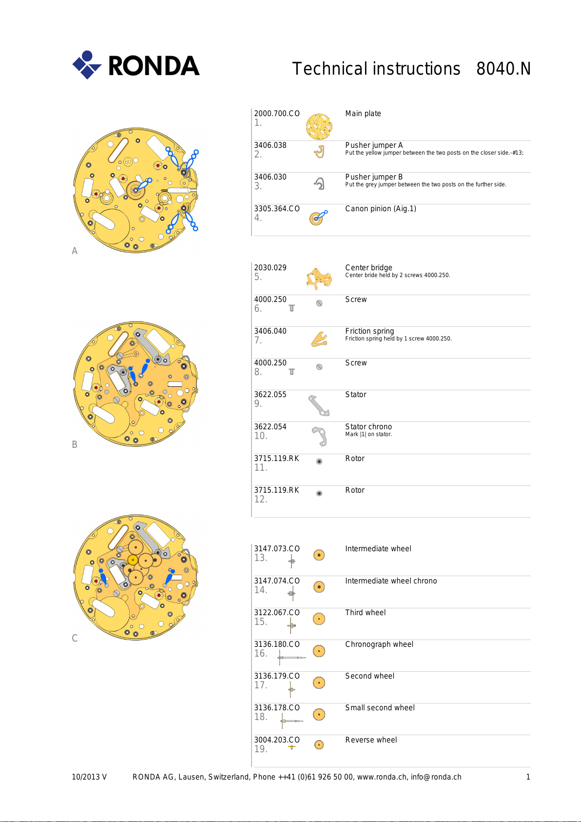
65,5% = 40mm Druchmesser
III
65,5% = 40mm Druchmesser
III
65,5% = 40mm Druchmesser
III
65,5% = 40mm Druchmesser
III
65,5% = 40mm Druchmesser
III
A
M
O
N
T
U
E
W
E
D
T
H
U
F
R
I
S
A
T
S
U
N
15
60
30
45
23
30
10
20
10 1
2
3
4
5
6
7
8
9
III III
M
O
N
T
U
E
W
E
D
T
H
U
F
R
I
S
A
T
S
U
N
15
60
30
45
23
30
10
20
10 1
2
3
4
5
6
7
8
9
III
M
O
N
T
U
E
W
E
D
T
H
U
F
R
I
S
A
T
S
U
N
15
60
30
45
17
30
10
20
10 1
2
3
4
5
6
7
8
9
II III
I
M
O
N
T
U
E
W
E
D
T
H
U
F
R
I
S
A
T
S
U
N
15
60
30
45
22
30
10
20
10 1
2
3
4
5
6
7
8
9
III
M
O
N
T
U
E
W
E
D
T
H
U
F
R
I
S
A
T
S
U
N
15
60
30
45
01
30
10
20
10 1
2
3
4
5
6
7
8
9
I
M
O
N
T
U
E
W
E
D
T
H
U
F
R
I
S
A
T
S
U
N
15
60
30
45
31
30
10
20
10 1
2
3
4
5
6
7
8
9
III
M
O
N
T
U
E
W
E
D
T
H
U
F
R
I
S
A
T
S
U
N
15
60
30
45
23
30
10
20
10 1
2
3
4
5
6
7
8
9
15
60
30
45
23
30
10
20
10 1
2
3
4
5
6
7
8
9
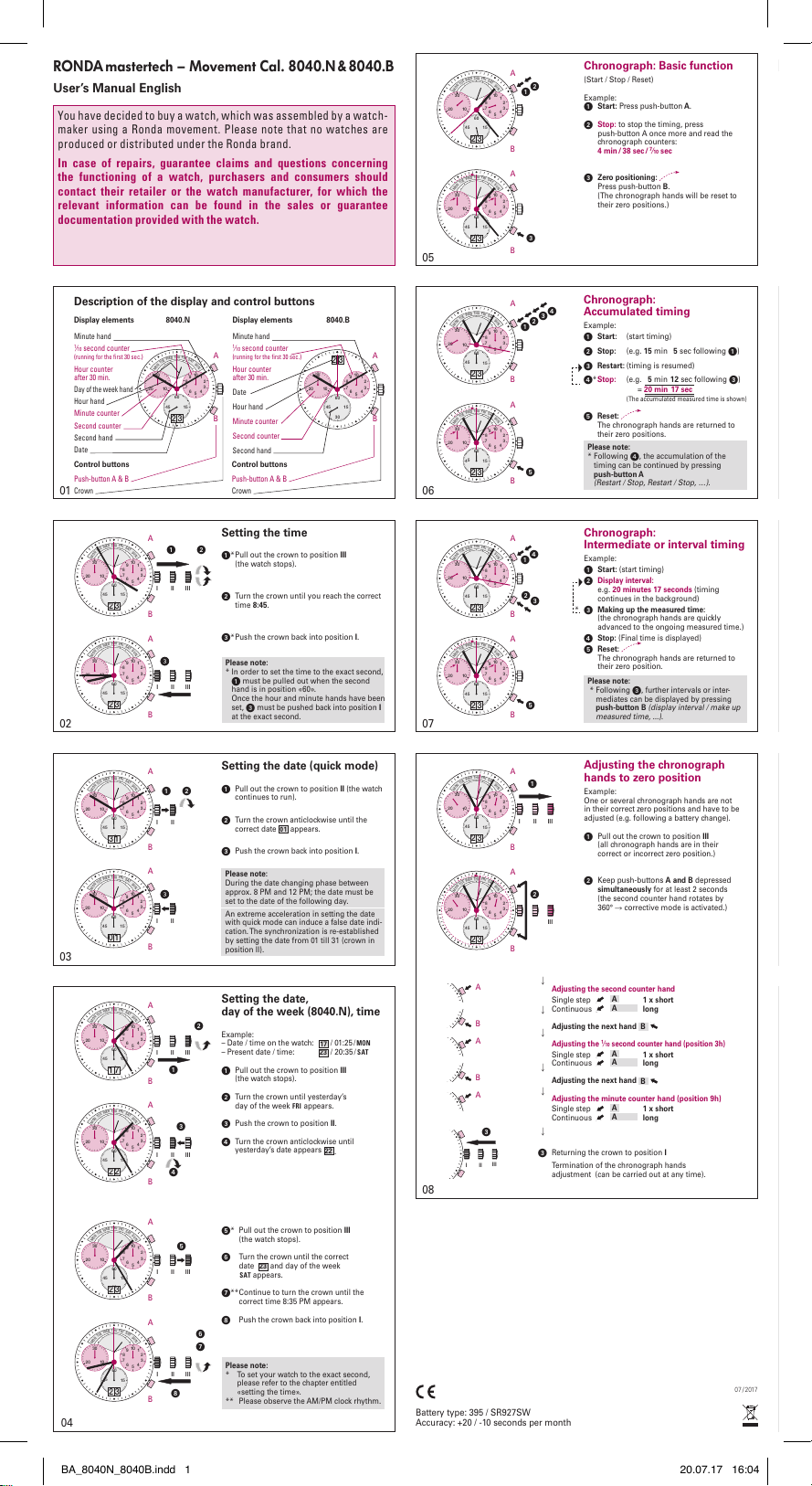
Display elements 8040.N
Minute hand
1⁄10 second counter
(running for the first 30 sec.)
Hour counter
after 30 min.
Day of the week hand
Hour hand
Minute counter
Second counter
Second hand
Date
Chronograph: Basic function
(Start / Stop / Reset)
Example:
Start: Press push-button A.
Stop: to stop the timing, press
push-button A once more and read the
chronograph counters:
4 min/38 sec/7⁄10 sec
Zero positioning:
Press push-button B.
(The chronograph hands will be reset to
their zero positions.)
Chronograph:
Accumulated timing
Example:
Start: (start timing)
Stop: (e.g. 15 min 5sec following
)
Restart: (timing is resumed)
*Stop: (e.g. 5min 12 sec following
)
= 20 min 17 sec
(The accumulated measured time is shown)
Reset:
The chronograph hands are returned to
their zero positions.
Please note:
* Following
, the accumulation of the
timing can be continued by pressing
push-button A
(Restart / Stop, Restart / Stop, …).
Chronograph:
Intermediate or interval timing
Example:
Start: (start timing)
Display interval:
e.g. 20 minutes 17 seconds (timing
continues in the background)
Making up the measured time:
(the chronograph hands are quickly
advanced to the ongoing measured time.)
Stop: (Final time is displayed)
Reset:
The chronograph hands are returned to
their zero position.
Please note:
* Following
, further intervals or inter-
mediates can be displayed by pressing
push-button B (display interval / make up
measured time, ...).
*
Adjusting the chronograph
hands to zero position
Example:
One or several chronograph hands are not
in their correct zero positions and have to be
adjusted (e.g. following a battery change).
Pull out the crown to position III
(all chronograph hands are in their
correct or incorrect zero position.)
Keep push-buttons A and B depressed
simultaneously for at least 2 seconds
(the second counter hand rotates by
360° corrective mode is activated.)
Adjusting the second counter hand
Single step
65,5% = 40mm Druchmesser
III
65,5% = 40mm Druchmesser
III
Along
Adjusting the next hand B
65,5% = 40mm Druchmesser
III
Adjusting the
1⁄10 second counter hand (position 3h)
Single step
65,5% = 40mm Druchmesser
III
65,5% = 40mm Druchmesser
III
Along
Adjusting the next hand B
65,5% = 40mm Druchmesser
III
Adjusting the minute counter hand (position 9h)
Single step
65,5% = 40mm Druchmesser
III
65,5% = 40mm Druchmesser
III
Along
Returning the crown to position I
Termination of the chronograph hands
adjustment (can be carried out at any time).
Setting the time
*
Pull out the crown to position III
(the watch stops).
Turn the crown until you reach the correct
time 8:45.
*Push the crown back into position I.
Please note:
* In order to set the time to the exact second,
must be pulled out when the second
hand is in position «60».
Once the hour and minute hands have been
set,
must be pushed back into position I
at the exact second.
Setting the date (quick mode)
Pull out the crown to position II (the watch
continues to run).
Turn the crown anticlockwise until the
correct date 01 appears.
Push the crown back into position I.
Please note:
During the date changing phase between
approx. 8 PM and 12 PM; the date must be
set to the date of the following day.
An extreme acceleration in setting the date
with quick mode can induce a false date indi-
cation.The synchronization is re-established
by setting the date from 01 till 31 (crown in
position II).
Setting the date,
day of the week (8040.N), time
Example:
– Date / time on the watch: 17 / 01:25 / MON
– Present date / time: 23 / 20:35 / SAT
Pull out the crown to position III
(the watch stops).
Turn the crown until yesterday’s
day of the week FRI appears.
Push the crown to position II.
Turn the crown anticlockwise until
yesterday’s date appears 22 .
* Pull out the crown to position III
(the watch stops).
Turn the crown until the correct
date 23 and day of the week
SAT appears.
**Continue to turn the crown until the
correct time 8:35 PM appears.
Push the crown back into position I.
Please note:
* To set your watch to the exact second,
please refer to the chapter entitled
«setting the time».
** Please observe the AM/PM clock rhythm.
User’s Manual English
RONDAmastertech – Movement Cal. 8040.N& 8040.B
07/ 2017
Battery type: 395 / SR927SW
Accuracy: +20 / -10 seconds per month
Display elements 8040.B
Minute hand
1⁄10 second counter
(running for the first 30 sec.)
Hour counter
after 30 min.
Date
Hour hand
Minute counter
Second counter
Second hand
Description of the display and control buttons
RONDAmastertech – Uhrwerk Kal. 8040.N&8040.B
Control buttons
Push-button A & B
Crown
Control buttons
Push-button A & B
Crown
B B
A A
You have decided to buy a watch, which was assembled by a watch-
maker using a Ronda movement. Please note that no watches are
produced or distributed under the Ronda brand.
In case of repairs, guarantee claims and questions concerning
the functioning of a watch, purchasers and consumers should
contact their retailer or the watch manufacturer, for which the
relevant information can be found in the sales or guarantee
documentation provided with the watch.
B
B
B
B
B
B
B
B
B
B
B
B
B
B
B
B
A
A
A
A
A
A
A
A
A
A
A
A
A
A
A
A
01
05
02
06
03
07
04
08
BA_8040N_8040B.indd 1 20.07.17 16:04