manuals.online logo
Brands
  1. Home
  2. •
  3. Brands
  4. •
  5. Ronstan
  6. •
  7. Winch
  8. •
  9. Ronstan Andersen Compact Motor 46ST User manual

Ronstan Andersen Compact Motor 46ST User manual

PRODUCT MANUAL
Compact Motor™
Below Deck
Electric Winch
46/50ST
FOR USE WITH:
Compact Motor™ Electric Winches
RA2046014100 RA2050014100
RA2046014200 RA2050014200
Compact Motor™ Conversion Kits
RA2046214100 RA2050214100
RA2046214200 RA2050214200
Winch Versions:
46ST (≥V.4.0) 50ST (≥V.1.0)
Your Winch Version No. ____________________________________
Your Motor Serial No. ________________________________________
710203 Rev.2
PRODUCT MANUAL
46/50ST Below Deck Compact Motor™
3
PRODUCT MANUAL
46/50ST Below Deck Compact Motor™
2
ANDERSEN Stainless Steel Winches®
Your Andersen winch is made with the care and craftsmanship that
come from more than sixty years of experience. Andersen winches
are built to last, to retain their exceptional nish and to deliver
season after season of reliable performance and sailing pleasure to
their owners through the years.
Compact Motor™ functionality
The Andersen Compact Motor™ is a brushless DC motor, carefully
matched to a low prole planetary gearbox, which requires less
space for installation and draws considerably less current than
traditional motor/gearbox congurations. Simplied electrical
installation requires no external control box.
The Compact Motor™ includes a dedicated circuit breaker with
integral controller and two illuminated “intelligent” push buttons
which regulate speed and power in the low and high speed ranges
of operation, in proportion to the pressure applied.
Manual operation is possible at any time using a normal winch
handle.
Monitoring and protection
The integrated controller will cause the motor to stop without
tripping the circuit breaker if one of the following conditions is
detected:
• Maximum pulling load exceeded. The motor will cut out if
the pre-set maximum pulling load of the winch for electrical
operation is exceeded. Operation can resume within a few
seconds when the load returns below the limit.
• Overheating. The motor will cut out if the temperature of the
motor circuit reaches 60˚C (140˚F). Operation can resume when
the temperature returns to normal.
• Maximum continuous run time exceeded. The motor will cut
out after running continuously for 4 minutes and 15 seconds.
Operation can resume after releasing the push button to pause
operation for at least 30 seconds.
In these cases, the illuminated push button will ash, indicating that
the controller will reset automatically when operating conditions
return to normal.
Read All Safety Notices and Product Manuals
Do not install or operate this winch before reading and fully understanding the contents of this Safety Notice Sheet and the
Product Manual.
Stay Alert When Operating
Andersen winches are very powerful and have the potential to cause signicant damage and/or serious injury if used
improperly or without due caution and vigilance.
Operators Must be Trained
Help prevent signicant damage and/or serious injury by ensuring any person operating a winch has a thorough
understanding of its proper operation and is aware of the potential hazards involved. As a minimum, all winch operators
must read and understand this Safety Notice Sheet and the Product Manual.
Particular attention is drawn to the following points:
• Children and others not qualied to operate an electric winch must be kept at a safe distance from the winch and any
rigging or ttings that are under load.
• Long hair and/or loose clothing must be tied back to avoid being caught in the winch.
• In the event of a rope override or other fault, stop the winch and turn o power before attempting to resolve the
problem.
Avoid Accidental Operation
Always turn o power to the winch at the circuit breaker and remove winch handles when not in use to help avoid
unsupervised or unintentional operation. Failure to do so could result in signicant damage and/or serious injury.
Maintenance
Turn o power to the winch before performing any maintenance or service tasks. Failure to do so could result in signicant
damage and/or serious injury.
Lifting Operations
The winch must not be operated with the rope in the self tailer when used in any kind of lifting operation. Any lifting
operations should be conducted by two persons in order to maintain constant visual contact with the object being lifted.
Furthermore the self tailer must not be used as a cleat for a rope used to lift or suspend any object. The rope must be
secured properly by tying o, or leading to a suitable tting such as a cleat or bollard.
Failure to observe these precautions could result in serious injury
or death.
DO NOT DISCARD
SAFETY NOTICES
Contents
PAGE
2Functionality
3 Safety notices
4Exploded view of assembly
and items included
5Parts list
6-10 Installation instructions –
motor and push button
11 Important notes - electrical installation
12 Wiring diagram
13-16 Electrical installation
17 Winch installation
18-19 Troubleshooting
20 LED status codes / diagnostics
21 Service and maintenance
22 Contact and warranty information
PRODUCT MANUAL
46/50ST Below Deck Compact Motor™
5
PRODUCT MANUAL
46/50ST Below Deck Compact Motor™
4
Push Button - E1, Two Speed & Three Speed Electric Winches
Scale 1:1
Page size A4 (210mmW x 297mmH)
Product No’s RA582000, RA582010, RA582020
Method A
Blue shaded areas of template
Drill a Ø19mm (3/4”) hole at the centre of the push button
location, and a Ø5mm (3/16”) hole immediately beside for
the breather tube (as indicated on the template).
Method B
Red shaded areas of template
Drill a Ø25mm (1”) hole at a 2mm (1/16”) o set to the centre
of the push button location (as indicated on the template).
RON-MDT/PBE1-Rev.2. 01-05-18
HOLE
Ø5mm
(3/16’’)
for breather
tube
12mm
(1/2’’)
20mm
(3/4’’)
HOLE
Ø19mm (3/4’’)
ON CENTRE
50mm
(1 15/16’’)
Cover in open position
50mm
(1 15/16’’)
2mm
(1/16’’)
37mm
(1 7/16’’)
3 HOLES
Ø3mm (1/8’’) TYP
25mm
(1’’)
50mm
(1 15/16’’)
HOLE
Ø25mm (1’’)
OFFSET 2mm from
centre of switch
9mm
(3/8’’)
Mounting Dimension Template
Andersen Winches™
ITEM NO. QTY DESCRIPTION PART NO.
1 1 Motor Compact BD, 12V for 46ST, 50ST RD825300
1 1 Motor Compact BD, 24V for 46ST, 50ST RD825500
2 1 Circlip RD829670
3 1 Gearwheel 584601
41 Grub screw DIN916-A4-M5x8
51 Clamping ring 584510
A1 1 Push button with plastic cover RA866000
A2 1 Push button gasket 735050
A3 1 Drilling template for 46ST, 50ST Compact BD
A3 1 Drilling template for RA866000 push button
A4 1 Hex keys, metric
A5 1 Eye bolt M6 RD100896
A6 1 Pin spanner, Ø5mm pins RD738000
A7 1 Push button labels RD100029
A8 3 Screw M4x20mm, self tapping RD100025
A9 1 Product Manual
A10 2 Control cable, 1000mm (39”) RD877610
A11 1 Circuit breaker with integral controller 877750
A12 1 Drain tube RD877408
A13 1 Compact BD Seal Service Kit RA710022
OPTIONAL ACCESSORIES:
Push button, stainless steel cover RA866010
Push button, stainless steel cover with hole RA866020
Control cable extension, 1000mm (39”) RD877610
Control cable extension, 4000mm (157”) RD877611
Drive Shaft & Housing Extension Kits Contact Dealer
A4
A8
A1
A2
A5
A6
A12A10
A11
A7 A13 A9A3 A3
PRODUCT MANUAL
Compact Motor™
Below Deck
Electric Winch
46/50ST
FOR USE WITH:
Compact Motor™ Electric Winches
RA2046014100 RA2050014100
RA2046014200 RA2050014200
Compact Motor™ Conversion Kits
RA2046214100 RA2050214100
RA2046214200 RA2050214200
Winch Versions:
46ST (≥V.4.0) 50ST (≥V.1.0)
Your Winch VersionNo. ____________________________________
Your Motor Serial No. ________________________________________
710203-Rev.1
Mounting Dimension Template
Andersen Winches
E1 & Compact Motor™Below Deck
Electric Self Tailing Winches, Size 58 & 62
230mm
91/16"
WINCHBASE
10.50mm[13/32"] x 6 EQUALLY
SPACEDON A 200mm [7 7/8"] P.C.D.
39.74mm
19/16"
29.00mm
11/8"
70mm
23/4"
CUTOUTFOR
ELECTRICMOTOR
60°
TYP
SELF-TAILINGARM CAN
BEREPOSITIONED IN
45DEGREE INCREMENTS
AFTERINSTALLATION
Scale 1:1
Page size A3
Product No. RA2058011300 RA2058011400 RA2058014100 RA2058014200
RA2062011300 RA2062011400 RA2062014100 RA2062014200
IMPORTANT
This template document has been created at 1:1 scale. It is critical that
it is printed at 1:1 scale. Check any printed/reproduced copies match
the dimensions indicated at 1:1 scale prior to use.
ART No: RD100214
MountingDimensionTemplate Part No. RD100214 - Rev.2
Exploded View
46/50ST Below Deck Compact Motor™ 12V/24V
Parts List
3
4
5
1
2
PRODUCT MANUAL
46/50ST Below Deck Compact Motor™
7
PRODUCT MANUAL
46/50ST Below Deck Compact Motor™
6
Required for installation
• Hex keys, metric (included)
• Pin spanner, 5mm pins (included)
• Cross head screwdrivers
• Drill bit Ø8.5mm for M8 mounting bolts (or drill bit 11/32” for 5/16” bolts)
• Drill bit Ø3mm (1/8’’)
• Ø70mm (2 3/4’’) hole saw, or jigsaw
• Ø25mm (1’’) hole saw
• 5x M8 (5/16’’) CSK mounting bolts and locking nuts (length as required for deck thickness)
• 5x M8 (5/16”) ID large washers, or backing plate to match drilling template
• Spanners: 13mm for motor and circuit breaker terminals, 10mm (1/2”) for winch mounting nuts
• Sealant / bedding compound
• Wire crimping tool/pliers
• Marine grade electrical power cables with lugs to suit your battery terminals and the M8 motor
and circuit breaker terminals
Before Installation
Before installation, record the version number of your winch and
the serial number of your motor in the space provided on the front
cover of this manual for future reference.
These details can be found as shown below.
Winch production year and month [YY-MM] followed by
version number are stamped on winch base between
the mounting bolt holes.
Installation Instructions
STEP 1
Determine the position of the winch and motor unit
1.1 Magnetic elds in the motor may aect compasses even
when the motor is not in use. Install the motor at least
1m (3ft) away from any compass, and always have your
compass recalibrated after installation.
1.2 The winch should be positioned with the recommended
line entry angle of 3-8° from horizontal.
1.3 Refer to the Winch Data Sheet for your winch model for
clearance/space requirements for the motor unit below deck.
You may choose to drill a small pilot hole to indicate the
position of the centre of the drive shaft, to assist with this.
1.4 Note the location of the drain port in the base of the motor.
If the mounting surface is not horizontal due to deck camber
or other factors, plan the installation such that the drain port
is situated at the lowest point in relation to the slope of the
mounting surface. The drain tube [A12] will be attached to
this port to allow any moisture from condensation to escape
and drain to the bilge.
Recommended line entry angle
Serial number engraved on bottom of motor.
3-8 degrees
PRODUCT MANUAL
46/50ST Below Deck Compact Motor™
9
PRODUCT MANUAL
46/50ST Below Deck Compact Motor™
8
STEP 2
Install the deck plate
2.1 Refer to the product manual for your 46 or 50ST winch.
Disassemble the winch and base cover to access the deck plate
for installation. Remove the plug in the base plate to expose the
octagonal hole where the motor drive unit will be connected.
2.2 The drilling template [A3] can be used to identify the locations on
deck for the mounting holes and deck cut-outs. The self-tailing
arm of the winch can be adjusted after installation into one of
eight dierent positions as indicated on the drilling template.
2.3 Use the drilling template as a guide for preparing the deck.
Ensure that the mounting surface is at and there is adequate
space and clearance on deck for the winch base and below
deck for the motor. With the drilling template in the desired
orientation, drill or cut the Ø70mm (2 3/4’’) hole for the motor
drive shaft housing.
2.4 Drill the Ø8.5mm holes for the M8 deck plate mounting bolts
(11/32” holes for 5/16” bolts).
2.5 Clean any wood or breglass splinters from the holes, and clean
the deck thoroughly to ensure deck sealant can adhere properly.
2.6 Apply sealant to the deck where the deck plate will be xed. For
aluminium boats use a galvanic isolating ring/gasket.
2.7 Fit the deck plate to the deck using appropriate length M8 or
5/16” countersunk head bolts, large washers or backing plate,
and locking nuts.
STEP 3
Fit the motor unit to the deck plate
Correct alignment of the motor during assembly is essential. Improper
alignment can cause excessive noise and vibration and lead to
premature wear of bearings and gears. For best results the following
steps should be carried out by two persons.
3.1 Refer to the exploded diagram and remove the circlip [2],
gearwheel [3] to expose the clamping ring [5].
3.2 Back out the locking grub screw [4] and use the pin spanner
[A6] to remove the clamping ring from the top of the drive shaft
housing, taking care that the O-ring underneath remains in place.
3.3 Screw the M6 eye bolt [A5] into the threaded hole in the top of
the drive shaft. Attach a strong rope or use a lifting device to raise
the motor unit into position so that the drive shaft protrudes
through the large octagonal hole in the deck plate.
3.4 Align the motor unit so that the protruding octagonal detail at the
top of the drive shaft housing mates snugly with the octagonal
recess in the deck plate, for a uniform ush t.
3.5 Fit and securely tighten the clamping ring using the pin spanner,
then insert and tighten the locking grub screw. Watertight
assembly is ensured by the O-ring under the deck plate; no
additional sealant is required.
3.6 After securing the clamping ring, reassemble the gearwheel and
circlip on the shaft.
3.7 Refer to the diagrams below to check for correct clearance and
alignment.
Octagonal detail on drive shaft housing
mates with recess in deck plate.
Correct mating of
drive shaft housing top ange
with underside of winch base
Incorrect mating of
drive shaft housing top ange
with underside of winch base
90°
Clamping Ring
Grub Screw
Clamping Ring
Grub Screw
Motor ange
Non-aligned hole in
deck preventing correct
motor alignment
Inadequate underdeck
clearance preventing
correct motor alignment
Deck Plate Deck Plate
Grub screw
protruding too
far
Clamping ring
not parallel to
deck plate
Typical self-tailing arm positions
2.
4.
Clamping ring
Grub screw
Drive shaft
Deck plate
O-ring
Eye bolt
Deck plate
Drive shaft housing
3.
Base plate plug removal
Drilling template use
5. Locking
grub
screw
PRODUCT MANUAL
46/50ST Below Deck Compact Motor™
11
PRODUCT MANUAL
46/50ST Below Deck Compact Motor™
10
STEP 4
Fit drain tube
4.1 Remove the plastic plug from the drain port tting and push the
drain tube [A12] into the tting until it stops. Lead the drain tube
below deck to a low point in the boat where it can drain to the
bilge, then cut o any excess length. At most there should only
ever be a drop or two of water from condensation that will pass
through the tube.
Warning!
The positive cable (+RED) must be connected to the positive (+RED) terminal of the motor. Incorrect polarity will cause
permanent damage to the motor.
Battery compatibility
Andersen Compact Motors™ produced from 2011 onward are compatible with wet cell, AGM and gel batteries. Furthermore
they may be used with Lithium-ion batteries supplied by Super B™, MasterVolt®and Victron®. These batteries have been
tested for compatibility and have built-in protection to prevent damage to the motor, battery and other elements of the
system. Other brands of Lithium-ion batteries are NOT approved for use with Andersen Compact Motors™.
Super B™ is a trademark of Super B International B.V.
MasterVolt®is a registered trademark of MasterVolt International B.V.
Victron®is a registered trademark of Victron Energy B.V.
Operation
The Andersen Compact Motor™ electric winch uses a brushless DC motor. Brushless DC motors draw current from the
battery when operating, and can send current back to the battery when spinning down unloaded. Avoid operating the
winch using the motor at high speed with no load on the drum, as spinning down an unloaded motor from high speed
can stress the motor and battery and could result in reduced service life or damage to the motor, battery or other elements
of the system.
Further Considerations
• Always disconnect power when not in use, and before performing any service or maintenance work on an
electric winch.
• Use only an original Andersen control cable to connect the push button to the Compact Motor™.
Extension cables may be ordered separately.
• Use only the Andersen circuit breaker supplied with your Compact Motor™; do not use it with other devices.
• Supply power to the motor only from the battery; never from an external power supply.
• Refer to the wiring diagram and cable size recommendations in the Andersen Winch Data Sheet for the model
and voltage corresponding to your Andersen Compact Motor™ Electric Winch.
• Never use solvents for cleaning control cables or wires – use only alcohol for this purpose.
Failure to observe these notices will invalidate the warranty.
Important Notes - Electrical Installation
Incorrect electrical installation will result in permanent damage
to the motor and invalidation of the warranty.
STEP 5
Install push button
The push button requires 50mm (2”) clearance depth below the
mounting surface. It is supplied with a short 190mm (7 1/2”) long
cable lead; this is connected below deck to the 1000mm (39”) long
control cable [A10] and then to the short cable leads from the motor.
Extension cables are available and may be ordered separately if
necessary.
5.1 Select the desired location. For safety reasons it is
recommended that the push button [A1] is located in close
proximity to the winch, preferably within reach.
5.2 Determine the preferred orientation of the hinged cover (on
vertical surfaces it should open upwards). Then using the
drilling template or the rubber gasket [A2] as a guide, drill a
Ø25mm (1”) hole.
5.3 Drill a Ø3mm (1/8”) hole in each of the three mounting screw
locations.
5.4 Fit gasket and push button in place. Secure the push button unit
with the 3x M4x20mm self tapping screws [A8], using a small
amount of sealant at each hole.
5.5 Ensure that the breather channel on the side of the through-deck
tube of the push button is clear and free of dirt or sealant.
Plastic plug
removed from
drain port
Drain port tting
Breather
channel
Drilling
template
Mounting
screws
Hinged
cover
Push
button
Rubber
gasket
Push button installation
PRODUCT MANUAL
46/50ST Below Deck Compact Motor™
13
PRODUCT MANUAL
46/50ST Below Deck Compact Motor™
12
The positive cable (+RED) must be
connected to positive terminal of
the motor.
INCORRECT POLARITY WILL
CAUSE PERMANENT DAMAGE TO
THE MOTOR AND INVALIDATE
THE WARRANTY!
WARNING
PUSH
BUTTON
[A1]
CONTROL
CABLE
[A10]
WINCH
MOTOR
[1]
THERMAL
SENSOR
WIRES
CIRCUIT BREAKER
CONTROLLER
[A11]
BATTERY
Wiring Diagram
Negative (
-
)
Terminal BLACK
M8 Thread
Positive (+)
Terminal RED
M8 Thread
Control cable
(connection to push button)
Thermal sensor wires
Drain port tting
with drain tube
Motor Detail
PRODUCT MANUAL
46/50ST Below Deck Compact Motor™
15
PRODUCT MANUAL
46/50ST Below Deck Compact Motor™
14
STEP 6
Prepare the power cables
6.1 Choose the shortest and most direct route possible for the cables, in order to minimise voltage drop between the
battery and the motor.
6.2 Measure the distance from the battery to the motor, and back again via the circuit breaker, to determine the necessary
total cable length.
6.3 Consult the table in the Winch Data Sheet for the model and voltage corresponding to your Andersen Compact Motor™
Electric Winch, to determine the minimum wire size for your cables according to the total cable length required for your
installation. If in doubt, consider choosing a thicker cable as this will help to minimise voltage drop.
6.4 Make up the cables with lugs to suit the terminals of your battery and the M8 terminals of the motor and circuit
breaker. The circuit breaker can accept cable lug size for max. wire size 50mm2.
STEP 7
Install the circuit breaker
7.1 Choose a suitable location for the circuit breaker [A11] in
an easily accessible position as close as possible to the
battery.
7.2 Connect the two thermal sensor wires from the motor to
the terminals marked “TER. SW” on the back of the circuit
breaker.
7.3 Use a 0.75mm2wire to connect the terminal marked
“MINUS” on the back of the circuit breaker to the
NEGATIVE (–) terminal of the battery.
Ensure that the circuit breaker is switched
to the “OFF” position before making any
wiring connections.
STEP 8
Connect power and push button cables
8.1 NEGATIVE (–) BLACK connection from motor to battery:
Connect the NEGATIVE (–) BLACK terminal of the motor to the
NEGATIVE (–) BLACK terminal of the battery using the (-) BLACK
power cable prepared in Step 6. Tighten the nut on the motor
terminal to a maximum torque of 12Nm (9 ft lb).
8.2 POSITIVE (+) RED connection from motor to circuit breaker:
Connect the POSITIVE (+) RED terminal of the motor to the
terminal marked “+ MOTOR” on the circuit breaker using the
(+) RED power cable prepared in Step 6. Tighten the nut on the
motor terminal to a maximum of 12Nm (9 ft lb). Ensure that the
cable lug is not touching the printed circuit board, and tighten
the nut on the circuit breaker terminal to a maximum torque of
5Nm (4 ft lb).
8.3 POSITIVE (+) RED connection from circuit breaker to battery:
With the circuit breaker switched to the “OFF” position, connect
the terminal on the circuit breaker marked “+ BATTERY” to
the POSITIVE (+) RED terminal of the battery using the (+) RED
power cable prepared in Step 6. Ensure that the cable lug is not
touching the printed circuit board, then tighten the nut on the
circuit breaker terminal to a maximum torque of 5Nm (4 ft lb).
8.4 Connect the push button control cables [A10] to the short cable
leads at the push button and the motor.
Connect thermal sensor
wires from motor
Connect cable from Negative (-)
terminal of the battery
Circuit breaker wiring connections
Motor (-)
Circuit Breaker,
marked “+ MOTOR”
Battery (+)
Battery (-)
Motor (+)
Circuit Breaker,
marked “+ BATTERY”
PRODUCT MANUAL
46/50ST Below Deck Compact Motor™
17
PRODUCT MANUAL
46/50ST Below Deck Compact Motor™
16
STEP 10
Winch Installation
10.1 Use a hex key to remove the screws at the top of the winch,
then lift o the self-tailing arm and the drum to expose the
centre stem and gears, and remove the base cover ring. Position
the centre stem of the winch on the deck plate with mounting
holes aligned, and secure it to the deck plate. Then secure the
base cover ring and t the drum.
STEP 9
Check installation
9.1 The PCB at the rear of the circuit breaker is tted with 3 LED
indicators, located along its edge as indicated in the photo.
Yellow LED
The yellow LED may signal a status code by emitting a
sequence of ashes once every 20 seconds. Count the
number of ashes and refer to the Troubleshooting
section of this manual.
Red LED
The red LED ashes when a fault has been detected.
Refer to the Troubleshooting section of this manual.
Green LED
In normal operation the green LED illuminates
continuously for the rst 5 minutes after switching to
“ON”, and ashes once every 20 seconds thereafter.
It will stop ashing a few seconds after switching the
circuit breaker to “OFF”.
Fault Possible Causes Action
Green LED does not illuminate. Circuit breaker is OFF, or there is a poor
connection of MINUS wire from the circuit
breaker to NEGATIVE (-) battery terminal.
Verify the connection of the MINUS
wire, see step 7. Then check that the
circuit breaker is ON.
Green LED remains illuminated
continuously for more than a
few seconds after switching
circuit breaker to OFF.
Cables on the circuit breaker terminals
labelled MOTOR and BATTERY have been
inverted.
With the circuit breaker OFF, swap the
cable connections to these terminals on
the circuit breaker and then try again.
Red LED ashes 4 times,
followed by Green and Yellow
both ashing.
No MINUS wire connected, or incorrect/
faulty connections to the PCB terminals.
Review details of steps 7 and 8, check all
connections to the circuit breaker.
RED
Positive (+)
to Motor (+)
RED
Positive (+)
to Battery (+)
Thermal sensor
wires to Motor
Pre-wired
at factory
“Minus” (-) wire to
Battery Negative (-)
LED Status
Indicators
LED status indicators
9.2 Switch the circuit breaker to “ON”. The green LED on the PCB at the rear of the circuit breaker should illuminate. Switch
the circuit breaker back to “OFF”. The green LED should go o after a few seconds. If this is not the case, refer to the
table below.
9.3 Verify that the push buttons are illuminated. If not, check connection of push button control cables.
9.4 With the circuit breaker switched to “ON”, test the motor by pressing one of the push buttons. Bring the motor
gradually up to half speed, and then gradually release pressure on the button until it slows to a stop. The motor and
gearbox operation should be smooth and quiet.
1.
3.
2.
4.
Winch installation
10.2 Test the winch by rotating the drum by hand and operating the winch manually with handle. The winch should operate
smoothly in both gears. Then remove the handle and test electrical operation by pressing the push button.
PRODUCT MANUAL
46/50ST Below Deck Compact Motor™
19
PRODUCT MANUAL
46/50ST Below Deck Compact Motor™
18
Troubleshooting
Compact Motor™ electric winches have built-in monitoring and protection features to enhance safety and avoid permanent
damage to the electronic and mechanical components of the motor and winch.
Automatic cut-out and reset
The integrated controller will cause the motor to stop without tripping the circuit breaker if one of the following conditions is
detected:
• Maximum pulling load exceeded. The motor will cut out if the pre-set maximum pulling load of the winch for electrical
operation is exceeded. Operation can resume within a few seconds when the load returns below the limit.
• Overheating. The motor will cut out if the temperature of the motor circuit reaches 60˚C (140˚F). Operation can resume
when the temperature returns to normal, which may take some time.
• Maximum continuous run time exceeded. The motor will cut out after running continuously for 4 minutes and 15
seconds. Operation can resume after releasing the push button for a pause of at least 30 seconds.
In these cases, the illuminated push button will ash, indicating that the controller will reset automatically when operating
conditions return to normal.
Fault detection and identication
If a fault occurs that requires investigation or intervention, the LED indicators on the circuit breaker can assist with
troubleshooting and diagnostics. These indicators are located along the edge of the PCB, at the rear of the circuit breaker as
shown in step 9 of this manual.
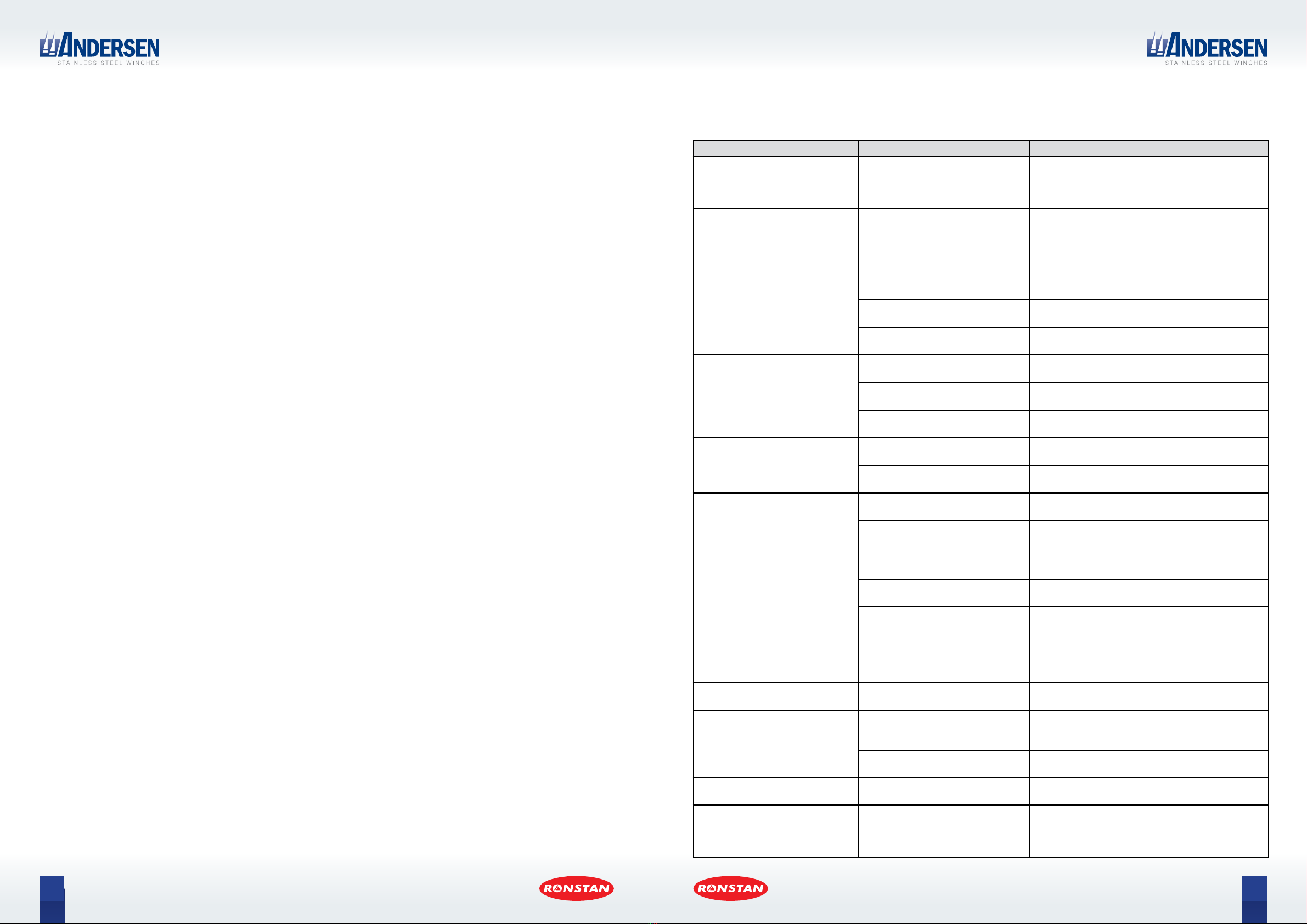
FAULT POSSIBLE CAUSE ACTION
Excessive vibration or noise
from motor/gearbox unit.
Drive shaft housing not mating
properly with octagonal recess
in deck plate, clamping ring not
tightened properly.
Ensure proper assembly with deck plate, and
sucient clearance with through-deck hole – see
step 3. Ensure clamping ring is fully tightened
before inserting and tightening locking grub screw.
Motor stops;
push button LED ashes
The motor has cut out after
reaching the pre-set maximum load
for electrical operation of the winch.
Release the push button and run the winch with
reduced load.
Motor circuit overheated;
temperature above 60˚C (140˚F).
When the motor has cooled down suciently (this
may take some time), status will automatically
reset to normal and the winch will be ready for use.
Ensure adequate ventilation around the motor.
Running time has exceeded +/- 4
minutes.
Release the push button and start again after
30 seconds.
Damaged control cable (push
button to motor). Replace cable if necessary.
Motor will not start; push button
LED not illuminated.
Circuit breaker and/or battery
switch may be “OFF”. Check and switch to “ON”.
No power supply to motor. Check power cables are properly connected to the
battery and circuit breaker.
Push button disconnected. Check control cables for push button and motor
are connected.
Motor will not start; push button
LED is illuminated.
Incorrect or insucient voltage in
power supply to motor. Restore normal voltage to power supply.
Damaged control cable (push
button to motor). Replace cable if necessary.
Circuit breaker trips and switches
to OFF after being reset.
Refer to LED Status Code table in
this section of the manual.
Address fault identied in LED Status Code table
and reset the circuit breaker.
Incorrect or insucient voltage in
power supply to motor.
Charge or change battery.
Check terminal connections.
Restore normal voltage to power supply and reset
the circuit breaker.
Thermal sensor wires disconnected
or damaged.
Re-connect thermal sensor wiring or replace if
damaged.
Motor circuit severely overheated;
temperature above 70°C (158˚F)
trips circuit breaker to OFF.
When the motor has cooled down suciently (this
may take some time), status will automatically
reset to normal and the winch will be ready for use.
Ensure adequate ventilation around the motor.
If problem persists or re-occurs contact your
Andersen dealer.
Circuit breaker trips and switches
to OFF while operating the winch.
Refer to Status Code Table in this
section of the manual.
Address fault identied in LED Status Code table
and reset the circuit breaker.
Green LED on circuit breaker does
not illuminate when circuit breaker
switched to ON, or ashes every
20 seconds in normal use.
MINUS wire from circuit breaker to
battery terminal is disconnected or
damaged.
Check cable and terminal connections at circuit
breaker and battery.
PCB or its terminals may be
damaged.
Contact your Andersen dealer, replace PCB if
necessary.
Circuit breaker trips, switches to
OFF and no status code ashes.
Current draw exceeds maximum
rating of circuit breaker.
Check electrical installation and ensure connections
to circuit breaker are correct.
Water drips from drain holes near
the base of drive shaft housing,
just above the motor/gearbox
unit.
May indicate water ingress through
drive shaft lip seal.
Follow the instructions in the service kit for lip
seal replacement provided with your Compact
Motor™, or contact your Andersen dealer for
assistance.
Troubleshooting Guide
PRODUCT MANUAL
46/50ST Below Deck Compact Motor™
21
PRODUCT MANUAL
46/50ST Below Deck Compact Motor™
20
GREEN
In normal operation the green LED illuminates continuously for the rst 5 minutes after
switching the circuit breaker to ON, ashes once every 20 seconds thereafter
and goes o a few seconds after switching the circuit breaker to OFF.
CONTINUOUS
with circuit breaker ON
In normal operation the green LED illuminates continuously for the rst 5 minutes after
switching to the circuit breaker to ON, and ashes once every 20 seconds thereafter.
CONTINUOUS
with circuit breaker OFF
Circuit breaker wired incorrectly; positive (+) cable connections to terminals labelled MOTOR
and BATTERY have been inverted.
FLASHING In normal operation, 5 minutes after switching the circuit breaker to ON the green LED will
switch from continuous illumination to ashing once every 20 seconds.
NOT ILLUMINATED
circuit breaker ON
Circuit breaker wired incorrectly; positive (+) cable connections to terminals labelled MOTOR
and BATTERY have been inverted.
NOT ILLUMINATED
circuit breaker OFF
In normal operation the green LED will go o a few seconds after switching the circuit
breaker to OFF.
RED The red LED will illuminate if a fault is detected. If a status code is available
it will be indicated by the ashing yellow LED.
NOT ILLUMINATED In normal operation the red LED will not be illuminated.
FLASHING 4 times, then yellow
LED starts ashing Check Yellow LED status codes below.
FLASHING
yellow LED not ashing
The circuit breaker can not be tripped by signal from PCB. Thermal sensor wires
disconnected, or incorrect connection of positive (+) cables between motor, circuit breaker
and battery.
FLASHING 4 times, then green
and yellow LED start ashing
MINUS wire from circuit breaker to negative (-) battery terminal not connected,
or incorrect/faulty connections to the PCB terminals.
YELLOW The yellow LED signals a status code by emitting a sequence of ashes once
every 20 seconds.
3 ashes High system voltage detected when power supply rst connected. Exceeds pre-set limit for
power up; check battery and any battery charging devices.
4 ashes High current draw detected when power supply rst connected. Exceeds pre-set limit for
power up; may indicate motor failure or incorrect wiring.
5 ashes Extremely low system voltage detected; check battery, charging devices and electrical
installation.
6 ashes Low system voltage detected; check battery, charging devices and electrical installation.
7 ashes Continuous low current consumption (≥ 15 minutes), check electric installation.
8 ashes Continuous low current consumption (≥ 8 minutes), check electric installation.
9 ashes High system voltage detected during operation; check battery and any battery charging
devices.
10 ashes Constant high system voltage detected; check battery and any battery charging devices.
11 ashes Status code not assigned.
12 ashes Status code not assigned.
13 ashes Motor overheated above 70°C (158˚F), or damaged thermal sensor wiring.
14 ashes Circuit breaker wired incorrectly; positive (+) cable connections to terminals labelled MOTOR
and BATTERY on the circuit breaker have been inverted.
LED Status Codes / Diagnostics
Periodic lubrication of the
motor drive shaft lip seal:
Lubrication of the motor drive shaft lip seal is recommended
once a year to condition the lip seal and avoid water ingress.
To access the seal for lubrication, remove the winch from
the deck plate.
Liberally apply a high quality bearing grease such as Klüber
Isoex® TOPAS NB52. Andersen Winch Grease may also be
used for annual lubrication.
Isoex® is a registered trademark of Klüber Lubrication München SE & Co. KG
Periodic replacement of the motor drive shaft lip seal
Replacement of the motor drive shaft lip seal is recommended every 3 to 5 years, depending on usage, in order to avoid
water ingress and ensure a long and trouble-free service life. In practice every 5 years will be sucient for most users, while
the shorter interval is advisable for winches that see more constant usage or are installed in more exposed installations.
A service kit is provided with your new Compact Motor™ for the rst lip seal replacement. It includes step-by-step
instructions for the procedure and all necessary spare parts.
Winch inspection & service
Inspection and service of your Andersen winch is recommended at two year intervals. For information consult the separate
product manual for your winch model which contains instructions, assembly diagrams and information about spare parts.
Product manuals are available for download from the Andersen website.
Service and Maintenance
Proper care and maintenance of your Andersen products will ensure many years of reliable service. For your Compact
Motor™ unit it is essential that the following service procedures are carried out at the recommended intervals.
Safety First! Always disconnect power before performing any service
or maintenance work on an electric winch.
Liberally apply a high quality bearing grease
Contact
Andersen Stainless Steel Winches®are manufactured by Ronstan Denmark ApS.
Jægervænget 36,
7100 Vejle
Denmark
[email protected]
WORLDWIDE DISTRIBUTION & SERVICE
Visit www.andersenwinches.com
WARRANTY
Visit www.andersenwinches.com
Andersen Stainless Steel Winches®is a registered trademark of Ronstan Denmark ApS

This manual suits for next models

9

Other Ronstan Winch manuals

Ronstan BB Orbit Block 20 Series User manual

Ronstan

Ronstan BB Orbit Block 20 Series User manual

Ronstan Andersen 34ST User manual

Ronstan

Ronstan Andersen 34ST User manual

Ronstan Andersen 18ST FS User manual

Ronstan

Ronstan Andersen 18ST FS User manual

Ronstan ORBIT WINCH 40QT User manual

Ronstan

Ronstan ORBIT WINCH 40QT User manual

Ronstan ORBIT WINCH 30QT User manual

Ronstan

Ronstan ORBIT WINCH 30QT User manual

Ronstan ORBITBLOCKS User manual

Ronstan

Ronstan ORBITBLOCKS User manual

Ronstan ANDERSEN Compact Motor 58ST User manual

Ronstan

Ronstan ANDERSEN Compact Motor 58ST User manual

Ronstan ORBIT Series User manual

Ronstan

Ronstan ORBIT Series User manual

Ronstan Andersen 28ST FS User manual

Ronstan

Ronstan Andersen 28ST FS User manual

Ronstan ANDERSEN Classic 10 User manual

Ronstan

Ronstan ANDERSEN Classic 10 User manual

Ronstan Andersen 28ST User manual

Ronstan

Ronstan Andersen 28ST User manual

Ronstan ORBIT WINCH RA6402 40QT User manual

Ronstan

Ronstan ORBIT WINCH RA6402 40QT User manual

Ronstan ORBIT WINCH 20ST User manual

Ronstan

Ronstan ORBIT WINCH 20ST User manual

Ronstan Compact Motor 68/72ST User manual

Ronstan

Ronstan Compact Motor 68/72ST User manual

Ronstan Andersen 40ST User manual

Ronstan

Ronstan Andersen 40ST User manual

Ronstan Andersen 12ST User manual

Ronstan

Ronstan Andersen 12ST User manual

Ronstan Andersen Compact Motor 52ST User manual

Ronstan

Ronstan Andersen Compact Motor 52ST User manual

Ronstan Andersen Compact Motor 68ST User manual

Ronstan

Ronstan Andersen Compact Motor 68ST User manual

Popular Winch manuals by other brands

Comeup CWL-200 manual

Comeup

Comeup CWL-200 manual

Comeup Seal Gen2 9.5 quick start guide

Comeup

Comeup Seal Gen2 9.5 quick start guide

Fransgard V-4000 manual

Fransgard

Fransgard V-4000 manual

TJM 947TJMTQ95SAA Fitting instructions

TJM

TJM 947TJMTQ95SAA Fitting instructions

Antal XT44/AL Installation and maintenance manual

Antal

Antal XT44/AL Installation and maintenance manual

Paccar BRADEN HP125B Installation maintenance and service manual

Paccar

Paccar BRADEN HP125B Installation maintenance and service manual

Runva 750CCA quick start guide

Runva

Runva 750CCA quick start guide

haacon 1524.0,5 operating instructions

haacon

haacon 1524.0,5 operating instructions

MayPole MP1420 Insructions

MayPole

MayPole MP1420 Insructions

AL-KO 351 Instructions for use

AL-KO

AL-KO 351 Instructions for use

Warn Zeon Control Pack Relocation Kit installation guide

Warn

Warn Zeon Control Pack Relocation Kit installation guide

Cequent FULTON instructions

Cequent

Cequent FULTON instructions

Good F850 Stealth Series Owner's Manual & Installation Instructions

Good

Good F850 Stealth Series Owner's Manual & Installation Instructions

Andersen 58/62 STE SE manual

Andersen

Andersen 58/62 STE SE manual

RAM 1550-8 AK1G Instructions, parts and maintenance manual

RAM

RAM 1550-8 AK1G Instructions, parts and maintenance manual

Superwinch ATV1800 owner's manual

Superwinch

Superwinch ATV1800 owner's manual

Parkside PSZ 250 B2 Operation and safety notes

Parkside

Parkside PSZ 250 B2 Operation and safety notes

haacon TANGO WV 300 operating instructions

haacon

haacon TANGO WV 300 operating instructions

manuals.online logo
manuals.online logoBrands
  • About & Mission
  • Contact us
  • Privacy Policy
  • Terms and Conditions

Copyright 2025 Manuals.Online. All Rights Reserved.