Rosco BSSK1000 Instruction Manual

Wireless Ultrasonic Parking Sensor
Systems for Commercial Vehicles
BSSK1000 &BSSK1001
INSTALLATION / USER'S MANUAL
BSSK1000:
Under Mount Backup Sensor System
BSSK1001:
Flush Mount Backup Sensor System

BSSK1000/1001 - INSTALLATION MANUAL BSSK1000/1001 - INSTALLATION MANUAL
Rosco ultrasonic wireless backup sensor systems provide safety advantages that protect drivers, vehicles
and business profits. These systems are ideal for school buses, work trucks, RVs and other commercial
vehicles. The wireless backup sensor system is automatically activated when the driver shifts into reverse
gear. Small flush or surface mount sensors are installed at the rear of the vehicle. The sensors send and
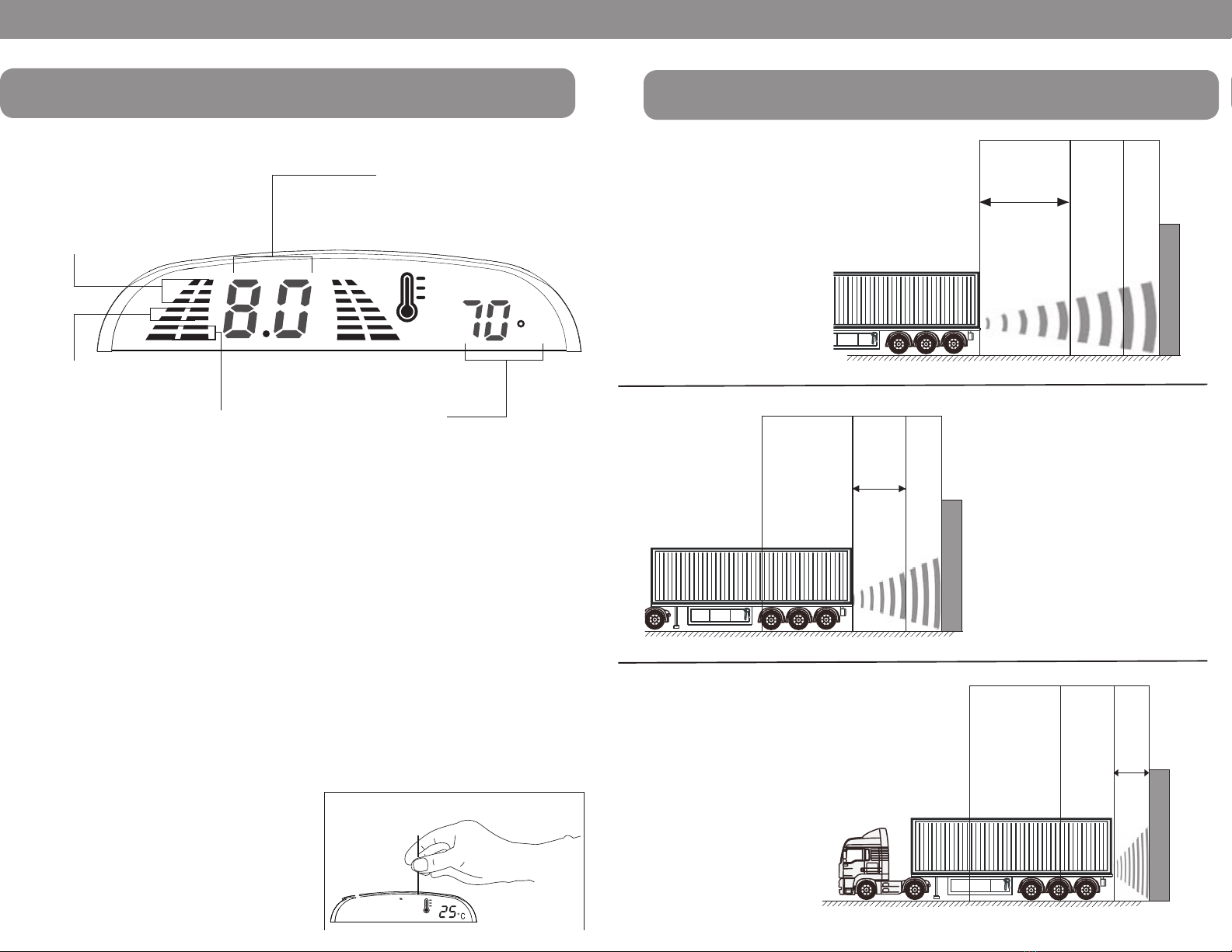
receive ultrasonic waves that reflect off obstructions and alert the driver to their presence. There is an
audible alarm that gradually increases in frequency as you approach the obstacle, and an LCD screen
displays the distance to the obstruction. A continuous "beep" and red distance indicator alerts the
driver when the vehicle is within one (1) foot of the obstruction.
Technical Specifications:
Operating range: DC9 ~ 32V
Operating current: 20-150mA @ 12V
Detection distance: 8.0 ~ 0.0 ft
Ultrasonic frequency: 40KHz
Working temperature: -22 ~ 158°F
Display size: 3.7 x 1.9 x 0.8 inches
Sensing resolution 0.5 ft
Installation Tools:
How To Read Display.................................................................................... 3
Sensor Detection Range & Warning Method ............................................. 4
Sensor Installation..........................................................................................5
Control Box Installation................................................................................. 6
Wiring Diagram.............................................................................................. 7
Display Installation...........................................................................................7
Testing & Maintenance....................................................................................8 8
2
1. Wire Tester 4. Wire Stripper 7. Drill
2. Phillips Screwdriver 5. Pencil 8. Tape
3. Tape Measure 6. Hole Saw
1.
2.
3.
4.
5.
6.
7.
8.
WIRELESS BACKUP SENSOR KIT WITH ULTRASONIC TECHNOLOGY
CONTENTS BSSK1000 UNDER MOUNT BACKUP SENSOR SYSTEM COMPONENT LIST:
Components: P/N Qty.
LED Display w/Double Sided Tape BSSKD200 1
Control Box BSSKT300 1
Under Mount Sensors (Set of 4) w/Hardware Kit BSSKS100 1
Hardware Kit Group 1: Foam Wedges 8
Hardware Kit Group 2: Screws and Washers 12
Hardware Kit Group 3: Tie Wraps 15
BSSK1001 FLUSH MOUNT BACKUP SENSOR SYSTEM COMPONENT LIST:
Components: P/N Qty.
LED Display w/Double Sided Tape BSSKD200 1
Control Box BSSKT300 1
Flush Mount Sensors (Set of 4) w/Hardware Kit BSSKS101 1
Hardware Kit Group 1: Washers 8
Hardware Kit Group 2: Screws 4
Hardware Kit Group 3: Tie Wraps 15
BSSKS100 BSSKS101
BSSKT300
BSSKD200
• Please read this manual carefully before using the product.
• This system is intended as an aid to safe reverse operation. Drivers must always use extreme
caution when operating a vehicle
• Sensors are to be used as parking aides for fixed objects such as vehicles and buildings.
They are not to be used for pedestrian detection.
WARNING
12

BSSK1000/1001 - INSTALLATION MANUAL BSSK1000/1001 - INSTALLATION MANUAL
Both the Flush and Under Mount backup sensor
systems are automatically activated when the
driver shifts into reverse gear.
There are three (3) volume options. They are
HIGH, LOW and OFF. The adjustment switch is
on the back cover of the display unit.
UNIQUE ID
Each control box has a unique ID to ensure
secure data transmission from control box to the
display. The display has the capability to pair
with a new control box. This allows the customer
to replace the display or control box if necessary.
F
Green Lights
Safe Zone
(8.0 ft to 3.5 ft)
Yellow Lights
Caution Zone
(3.0 ft to 1.0 ft)
Distance (ft)
Red Lights
Danger Zone
(1.0 ft to 0.0 ft)
Cabin Temperature
Press the button
How To Reprogram The Display:
1. Turn ignition on (DO NOT START).
2. Put the car in reverse.
3. Press the button on back of display
one time for about 5 seconds. (See Below)
4. Display will store the unique
ID of the nearest control box automatically.
HOW TO READ DISPLAY
OBSTRUCTION
3.0 ft
to
1.0 ft
Caution
Zone
8.0 ft to 3.5 ft
Safe
Zone
OBSTRUCTION
1. Safe Zone
Distance Display:
8.0 to 3.5 ft.
Alarm Sound:
8.0 to 5.5 ft. - None
5.0 to 3.5 ft. - Slow "Beep"
LED Lights:
Green
2. Caution Zone
Distance Display:
3.0 to 1.0 ft.
Alarm Sound:
Fast "Beep"
LED Lights:
Yellow
3. Danger Zone
Distance Display:
1.0 to 0.0 ft.
Alarm Sound:
Continuous "Beep"
LED Lights:
Red
OBSTRUCTION
1.0 ft
to
0.0 ft
Danger
Zone
SENSOR DETECTION RANGE & WARNING METHOD
34

BSSK1000/1001 - INSTALLATION MANUAL BSSK1000/1001 - INSTALLATION MANUAL
6
Figure. 1
IMPORTANT:
The sensor installation steps are applicable
to BOTH the Flush Mount and Under Mount
Backup Sensor Systems.
The individual sensors are labeled A, B, C, and
D. The sensors should be installed in the
following order:
Sensor A: Outer Driver Side
Sensor B: Inner Driver Side
Sensor C: Inner Passenger Side
Sensor D: Outer Passenger Side
It is highly recommended to install all four (4)
sensors. The system however, will work with
less than four if the vehicle configuration cannot
accommodate all the sensors.
1. For all setups, installer MUST
make certain that sensors are
centered both horizontally
and vertically.
2. Installation height for sensors
should be between 1 to 4 ft.
above ground.
3. Sensors A & D should be located
6 to 9 inches from outer edge of vehicle.
4. When installing sensors, make
certain that no part of vehicle (hitch,
etc.) is within 90° of the sensing range.
5. When installing sensors be certain
the sensor is level, not at a angle.
Place provided washers and
wedges if necessary.
6. Surface to install sensors must be
vertical and flat.
2-2.5ft
1-4ft
6” - 9” 1’ - 1.5’
1-1.5ft
6-9’
ABCD
AD
ABCD
2-2.5ft
1-4ft
6” - 9” 1’ - 1.5’
1-1.5ft
6-9’
ABCD
AD
ABCD
Figure. 2
Figure. 3
5
Control box
Figure. 1
Control box
Figure. 2
Control box
Figure. 3
SENSOR INSTALLATION SENSOR INSTALLATION
IMPORTANT:
The marked sensor cables (A,B,C,D) must be
connected to the corresponding marked inputs on
the control box. See page 7.
1. Control Box MUST be installed in
the cargo area or other protected area.
2. After choosing a suitable control box position in
the vehicle, drill the required holes to route the
sensor cables to vehicle interior.
3. Pull sensor cables through drilled
hole to vehicle interior.
4. Connect sensors cables to the control box.
5. Connect power and ground wires to
the reverse light circuit.

BSSK1000/1001 - INSTALLATION MANUAL BSSK1000/1001 - INSTALLATION MANUAL
IMPORTANT: The marked sensor cables (A,B,C,D) must be connected to the matching marked
inputs on the control box.
1. Select an area easily visible to the
driver and mount display firmly.
Clean surface with alcohol and use
the included double sided tape to
mount. (Figure 1)
2. Connect RED wire from display
unit to ignition/switch power source.
3. Connect BLACK wire to vehicle ground.
4. Locate optional temperature sensor as desired.
5. Power up and test.
Control box
Sensors
A.
B.
C.
D.
A.
B.
C.
D.
To Termination/Chassis Ground
To Positive 12V Wire on the Reverse Light Circuit
Red 12V Wire
Black Ground Wire
30"
7" 8'
8'
8'
8'
7"
7"
7"
DISPLAY INSTALLATION
WIRING DIAGRAM
5.0ft
1. Apply the parking brakes.
2. Turn Ignition on (DO NOT START).
3. Place the shift gear to reverse position.
4. From behind the vehicle proceed to check the system by placing an item back
and forth in front of each sensor.
Maintenance:
Always keep sensor clear from dirt, snow, and mud. Clean sensors with a soft towel and
low pressure water.
Trouble Shooting:
Problem Cause Solution
No power to display. Bad power connections. Check power
connections.
Display on, but no
reading while reversing.
Display not synchronized with
control box.
Press button on back of display
for five (5)
seconds to sync with control
box.
Orientation of sensors
do not match.
Sensor cables installed to
wrong control box ports.
Check and change the sensor
cables to correct ports on
control box.
System always detects the
same distance.
Sensor may be detecting
ground or debris
(mud, snow, etc).
Check and adjust the vertical
angle on the
sensor. Clean sensor of any
debris.
HOW TO TEST
7 8

NOTES
NOTES
9 10

Lit. P/N: MO071615
A CENTURY OF AUTOMOTIVE VISION SAFETY
90-21 144th Place, Jamaica, New York 11435
TEL (800) 227-2095 • FAX (718) 297-0323
This manual suits for next models
1
Table of contents
Other Rosco Automobile Accessories manuals

Rosco
Rosco STSK453X Series Instruction Manual

Rosco
Rosco Dual-Vision XC4 User manual

Rosco
Rosco STSW1001 Series Instruction Manual

Rosco
Rosco STSK4532 Instruction Manual

Rosco
Rosco SAFE -T-SCOPE Instruction Manual

Rosco
Rosco STSK4531R Instruction Manual

Rosco
Rosco SAFE -T-SCOPE STSK7165 Instruction Manual

Rosco
Rosco DMG DASH User manual

Rosco
Rosco Safe-T-Scope STSK7565 Instruction Manual

Rosco
Rosco STSK453X Series Instruction Manual