STSK7165 USER MANUAL STSK7165 USER MANUAL
56
INSTALLATION INSTRUCTIONS
Note: The following instructions are for typical rearview application.
STSC101 CAMERA
1. Attach camera bracket close to rear marker lights, centered on vehicle (see Fig.1.)
Attachment point must be sturdy enough to support camera and bracket.
2. We do not recommend mounting the camera near the lower area of the
vehicle (e.g. bumper). This reduces the view of the camera and increases
the chance of physical damage to the camera.
3. Attach camera to bracket using screws provided. Adjust angle as indicated
in Fig. 2. (Use rear bumper and back of vehicle as a reference point.)
4. Wind deflector may be installed. This deflector is designed to reduce the
buildup of dust, dirt and moisture on the camera lens. (See Fig.3)
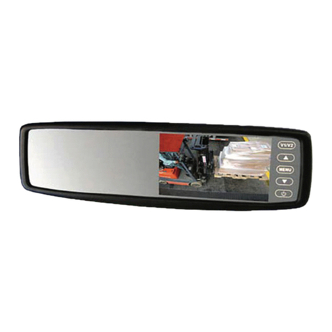
STSM205 MONITOR
1. Attach monitor inside vehicle in a location convenient to the driver (e.g.
center of dash, overhead, or flush-mounted in dash).
2. Attach “U” or “duckfoot“ bracket to the dashboard or to the headliner
using self-tapping screws and/or adhesive pad. (See Fig. 4.)
3. Fasten monitor to bracket and adjust mounting angle to allow optimum driver
viewing comfort.
CABLE
1. The camera to cable connection is waterproof. Be sure to position the cable
properly. The male end attaches to the camera. The female end attaches to the
power/video/audio distribution harness, typically located under the dashboard.
(See Fig. 5.)
IMPORTANT: For typical rear-view installation, the rear
camera MUST be connected to the distribution harness at
the connector marked “CA3”
2. Do not run the cable over sharp edges or corners. Do not kink the cable.
Keep the cable away from hot and rotating parts.
3. Fasten all cable runs, and secure all excess cable.
WIRING CAMERA AND MONITOR
1. See wiring diagram for connections to ignition, ground and “backup lights” circuit.
(See Fig. 5.)
2. Before drilling, be sure no cable or wire is on the other side. Be sure to drill a 20mm
(0.8in) diameter hole only.
3. Feed as much cable as possible into vehicle and clamp securely. This reduces
the possibility of it being hooked or snagged.
4. Keep all cables away from HOT, ROTATING and ELECTRICALLY NOISY components.
5. Camera: Drill a 20mm (0.75in) diameter hole into vehicle body near the camera
and bracket. Insert camera cable into vehicle (be careful not to kink cable) and fit
grommet into hole. Apply sealant around grommet to increase resistance to water
penetration. Connect camera to the camera extension cable which runs inside
the vehicle.
6. Monitor: The monitor terminates in a 13-pin male connector, which should be
connected to the mating 13-pin receptacle end of the power/video/audio distribution
harness.
7. For typical rear-view installation, connect the camera extension cable from the
rear-view camera to the harness’s connector marked CA3.
8. For multi-camera installations using cameras CA1 and/or CA2, be sure to mark each
extension cable properly and connect to the appropriate harness connector
marked CA1 or CA2. Bundle excess cable together using a cable tie or electrical tape.
9. Connect the red wire to an ignition power source, and connect the black wire to
chassis ground. The brown wire is the trigger wire. In typical rear-view installations,
connecting this wire to the vehicle’s backup light circuit will activate the rear-view
image whenever the vehicle shifts into reverse.
10. FUEL TANKERS & OTHER SPECIALTY VEHICLES: All electrical equipment fitted
to petroleum vehicles must be connected via battery master switch and must be
isolated from the battery while the vehicle are loading and unloading. For other
specialty vehicles, please check applicable code and regulations prior to installation.
11. Always consult your dealer when fitting any electrical or electronic equipment to a
vehicle fitted with a CAN-bus or multiplex system.
IMPORTANT: For installations requiring multiple cameras, or for installations not
requiring typical rear-view images, please refer to the wiring diagram (Fig.5) and the
particularvehicle’s electrical schematic for selection of proper power and trigger
connection points.
