Toro 04238 User manual

FormNo.3415-600RevB
TransportFrame
TransPro™80Tow-BehindTrailer
ModelNo.04238—SerialNo.230000801andUp
ModelNo.04244
ModelNo.04245
ModelNo.04247
InstallationInstructions
Safety
SafetyandInstructionalDecals
Safetydecalsandinstructionsareeasilyvisibletotheoperatorandarelocatednearanyarea
ofpotentialdanger.Replaceanydecalthatisdamagedormissing.
decal98-8687
98-8687
1.Thetrailertiresshouldbeinatedto0.35bar(5psi);read
theOperator’sManual.
decal106-4669
106-4669
1.Warning—donotcarrypassengers;donottowdownslopes
greaterthan15°;donotexceed24km/h(15mph);drive
inastraightlinewhenmovingfast;adjustyourspeed
accordingtogroundconditions.
©2018—TheToro®Company
8111LyndaleAvenueSouth
Bloomington,MN55420
Registeratwww.T oro.com.OriginalInstructions(EN)
PrintedintheUSA
AllRightsReserved*3415-600*B

Installation
TheTranspro80isintendedforusewithGreensmaster
800,1000,1010,1600,1610,2000,2600,aswellas
Flex18,21,1800,1820,2100,2120andeFlex1800,
1820,2100,2120WalkGreensmasters.
MountingtheTongue
Assembly
1.Insertthetongueassemblyintotheframe
assemblywhilealigningtherearmountingholes
(Figure1).
2.Securethetongueassemblyintotheframe
assemblywithaclevispin,2washersand2
cotterpins(Figure1).
g215365
Figure1
1.Tongueassembly4.Cotterpin
2.Frameassembly5.Washer
3.Clevispin
MountingtheAxleand
Ramp(Model04245)orRail
(Models04244and04247)
Assemblies
1.RefertoFigure2todeterminewhichmounting
holesthatyoushouldusetotthewidthofyour
Greensmower.
g014662
Figure2
1.Greensmaster1600,
Greensmaster1000
withgroomer,2000with
groomer,or2600
3.Greensmaster1000,Flex
21,2000,Flex2100,2120
andeFlex2100,2120
2.Greensmaster800,Flex
18,Flex1800,1820,and
eFlex1800,1820
Important:IfyourGreensmasterhas
agroomerattached,itwillbemounted
differentlythanabove;refertothefollowing
list:
•Greensmaster1000/2000or2100with
groomer:Theleftsideshouldbesetto
position#3andtherightsideshouldbeset
to#1.
•Greensmaster1800/eFlex1800with
groomer:Theleftsideshouldbesetto
position#2andtherightsideshouldbeset
to#3.
2.Mounttheaxleassemblyandarampassembly
(Figure3)orrailassembly(Figure4)toeach
endoftheframewith2bolts(3/8x3inches),
4washersand2nuts.
2

g215364
Figure3
1.Axleassembly4.Washer
2.Rightrampassembly5.Nut
3.Bolt(3/8x3inches)
g215363
Figure4
1.Axleassembly4.Washer
2.Rightrailassembly5.Nut
3.Bolt(3/8x3inches)
MountingtheWheel
Assemblies
1.Mountawheelassemblytoeachaxlehubwith
4lugnuts(Figure5).Tightenthenutsto108
N⋅m(80ft-lbs).
2.Adjustthetirepressureto5psi(34kPa).
g014665
Figure5
1.Axle2.Wheelassembly
Important:Highertirepressuremay
damagethemachine.
MountingandAdjustingthe
HitchStraps
Thehitchstrapsareshippedmountedinthestandard
position(Figure6).
Important:Thetrailertonguemustbeparallelto
thegroundwhenitisalignedwiththetowvehicle
hitch.
g014666
Figure6
Standardposition
3

UsingoneofthecongurationsshowninFigure7or
Figure8,adjustandsecurethehitchstrapstothe
trailertongue.
g014667
Figure7
Lowhitchposition
g014668
Figure8
Highhitchposition
MountingtheGreensmower
WheelAssemblies
(Models04244and04247only)
Note:OntheGreensmaster1000,1010,and2000
whenequippedwithagroomer,youmustremovethe
wheelshaftonthegroomerendandpurchaseand
installanewwheelshaft(PartNo.106–5385).Also,
youmustmounttherailassemblyonthegroomer
endtoGreensmaster1600and1610holelocations
(Figure2).
Note:OntheGreensmaster1800,1820,2100,
and2120whenequippedwithagroomer,you
mustremovethewheelshaftonthegroomerend
andpurchaseandinstallanewwheelshaft(Part
No.136–7287).
1.Removetheexistingstandardtransportwheels
fromthewheelshaftsontheGreensmower(if
equipped).
2.OntheGreensmasterFlex18or21only,
proceedasfollows:
A.Removetherightsidedrumcoverfromthe
machine(Figure9).
g017122
Figure9
1.Rightsidedrumdrive
cover
3.Rubbergrommet
2.Feltseal
B.Removeanddiscardtherubbergrommet
fromtheaxleholeinthedrumcover(Figure
9).
C.Afxthefeltsealtotheinsideofthecover
positioningitaroundtheaxlehole(Figure
9).
D.Installthecovertothemachine.
4

3.Insertawheelontoeachshaftandsecurewitha
wheelclip(Figure10).
Note:TheFlex1800,1820,and2100,2120
seriesrequiresadifferentwheeloffsetthanall
otherT oroGreensmowers.Readandfollowthe
mountinginstructionsmoldedintothesidesof
thewheels.
g014669
Figure10
Leftsideshown
1.Wheelshaft3.Wheelclip
2.Wheel
LoadingtheTrailer
1.Whilemaintainingcontrolofthetrailerbedand
holdingontothehandle,pressdownonthelatch
assemblyandthelifthandle(Figure11).Lower
thetrailerbedtotheground.
g014670
Figure11
1.Latchassembly2.Handle
2.Onatramps,pivotthewheelrodsupward
(Figure13)andonrailramps,rotatethewheel
rodsparallel(open)totheramp(Figure14).
3.Removethebasketfromthegreensmower,
disengagethereeldriveandmovethethrottle
totheslowestposition.Slowlydrivethegreens
mowerontothetraileruntilthewheelstopsare
contacted(Figure12).
4.Iftherailwheelsarenotcenteredontherails,
loosenthefastenerssecuringtherailstothe
trailerandadjusttherailpositionsotherail
wheelsarecentered,thentightenthefasteners.
5.Shutofftheengineandengagetheparking
brake.
6.Engagethewheelrodsasfollows:
5

•Onatramps,rotatethewheelrods
downwardoverthegreensmowertransport
wheels(Figure13).
•Onrailramps,liftthewheelrodandrotateit
behindthegreensmowertransportwheels
(Figure14).
g214902
Figure12
GreensMasterloadedonaTransPro80withRailKit
g014671
Figure13
1.Wheelrod(showninpivoteddownposition)
g014672
Figure14
1.Wheelrod(shownintheclosedposition)
7.Pushdownonthehandleuntilthetrailer
assemblylocksintothelatchassembly(Figure
11).
8.ForFlexGreensMastermachines,securethe
frontofthemachinebyhookingthebungee
strapstothebaskethoop.
Forxed-headGreensMastermachines,secure
thefrontofthemachinebyhookingthebungee
strapstothebaskethorns.
9.Storethebasketinthetowvehicle.
6

Operation
OperatingTips
1.TheTranspro80isintendedforusewith
Greensmaster800,1000,1600,2000,2600,
Flex18,21,1800,1820,2100,2120andeFlex
1800,1820,2100,2120WalkGreensmasters.
Thetowingofotherproductsmaydamagethe
axlesandtransmissionsthatcontinuetorotate
whentowed.
2.Useonlyavehiclewiththepropertowrating.
TheTranspro80and1greensmowerweigh
approximately400lb(182kg).Ensurethatthe
towvehiclehasadequatebrakingandhandling
capacitybycheckingtherecommendationsof
thevehiclemanufacturer.
3.Ensurethatthetrailerisproperlyconnectedto
thetowvehiclebeforeloadingorunloadingthe
greensmowertopreventsuddenunintended
tonguemovementoripup.Usearetention
deviceonthehitchpintosecuretheconnection.
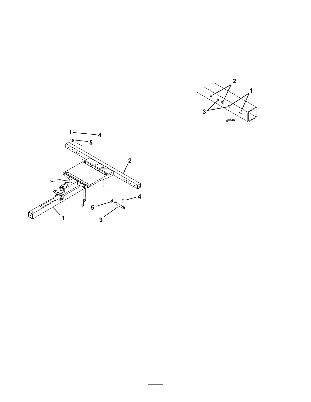
Important:Thetrailertongueshouldbe
paralleltothegroundwhenyoualignitwith
thetowvehiclehitch.
4.Duringtransport,usethebungeestraptosecure
thegreensmowertothetrailer(Figure15).You
canmovethebungeestraptodifferentmounting
holestoaccommodatedifferentmowers.
Note:Securethebungeestraptothegrass
baskethornsortothegrassbasketlooponthe
eFlex/Flex1800/2100models.
g014673
Figure15
1.Bungeestrap
5.TheTranspro80addsextratowingweighttothe
vehicle.Drivethevehiclesafely.
•Donotdriveonhighwayorpublicroads.
•Alwaysslowthetowvehiclewhen
approachingandwhilemakingaturn.
•Alwaysslowthetowvehiclewhendrivingin
unfamiliarareasoroverroughterrain.
•Alwaysslowthetowvehiclegraduallywhen
changingdirectionoftravelorpreparingto
stop.
•Whenturningordrivingonslopes,always
slowthetowvehicle,thenturntoprevent
lossofcontrolandpossibleupset.
•Donotmakesuddenorsharpturns.Donot
suddenlychangedirectionoftravelonan
incline,ramp,grade,slopeorsimilarsurface.
•Themaximumtowingspeedis15mph(24
kmh).Alwaysadjustthetowvehiclespeed
toallowforexistinggroundconditions,such
aswetslicksurfaces,loosesandorgravel
and/orlowvisibilityconditions,suchasdim
orbrightlighting,fog,mistorrain.
•Beespeciallycarefulwhendrivingaheavily
loadedvehicledownaninclineorslope.
Drivethevehicleupanddownthefaceof
theslopes,inclinesorgradeswhenever
possible.Donotdriveacrossthefaceifat
allpossible.Thereisariskofupsettingthe
vehicle,whichcanresultinseriousinjuryor
death.
6.Beforebackingup,looktotherearandensure
thatnooneisbehindyou.Backupslowlyand
watchthetrailermovementclosely.
7.Useextremecautionandslowspeedwhen
backingupthetrailerandtowvehicle.
8.Watchoutfortrafcwhennearorcrossingroads.
Alwaysyieldtherightofwaytopedestriansand
othervehicles
9.Ifthetrailerbeginstovibrateabnormally,stop
immediately.Shutoffthetowvehicleengine.
Repairalldamagebeforetowing.
10.Beforeservicingormakinganyadjustmentsto
thetrailer
•Stopthetowvehicleandsettheparking
brake.
•Shutoffthetowvehicleengineandremove
thekey.
11.Keepallnuts,boltsandotherfastenerstightened
securely.Replaceanypartsremovedduring
servicingoradjustments.
12.Toensureoptimumperformanceandcontinued
safetyofthisproduct,alwaysusegenuineToro
replacementparts.Replacementpartsand
accessoriesmadebyothermanufacturersmay
affecttheproduct’soperation,performanceor
durability.Suchusecouldalsovoidthewarranty
ofTheToroCompany.
7

Maintenance
RecommendedMaintenanceSchedule(s)
MaintenanceService
IntervalMaintenanceProcedure
Aftertherst10hours•Checkthetorqueofthewheellugnuts.
Yearly•Servicethewheelhubandinspectfordamage.
•Lubricatethewheelhubassembly.
ServicingtheWheelHub
ServiceInterval:Yearly
1.Raisethetraileronjackstands.
2.Removethe4lugnutssecuringthewheeltothe
wheelhubandremovethewheel.
3.Removethedustcapfromthewheelhub(Figure
16).
4.Removethecotterpinandretainerlocknut
(Figure16).
5.Removethehubnut,spindlewasherandhub
assemblyfromtheaxle(Figure16).
6.Inspectallofthehubassemblyparts,including
thebearings,bearingcups,andoilseal.
Replaceanydamagedparts.
g265352
Figure16
1.Dustcap6.Bearingcup
2.Retainerlocknut7.Hubassembly
3.Hubnut8.Oilseal
4.Spindlewasher9.Cotterpin
5.Rollerbearing10.Axleassembly
LubricatingtheWheelHub
Assembly
ServiceInterval:Yearly
1.Wipeawaytheexistinggreasefromthe
bearings,bearingcups,andhubassemblywith
aclean,dryrag.
2.Packthebearingcupsandinteriorsurfacesof
thehubassemblywithhigh-temperaturegrease
sothatthebearingsrollerfacesarecompletely
coated.
3.Installthebearingcupsandbearingstothehub
assemblyasshowninFigure16.
4.Cleanupanyexcessgreasefromtheoutsideof
thehubassembly.
InstallingtheWheelHubAssembly
1.Installtheoilseal,hubassembly,andspindle
washerasshowninFigure16.
2.Tightenthehubnutwhileturningthewheelhub
assemblytoseatthebearingsandremoveall
endplay.
3.Whileturningthewheelhubassembly,torque
thehubnutto8.5to20.3N⋅m(75to180in-lbs).
4.Loosenthehubnutuntilitdoesnotcontactthe
washerandthehubhasendplay.
5.Tightenthehubnutto1.7to2.3N⋅m(15to20
in-lbs)whilerotatingthehub.
6.Placetheretainerlocknutoverthehubnutso
thatthecotterpinholeisalignedwithasloton
theretainerlocknut.
7.Installanewcotterpinthroughtheslotinthe
retainerlocknutandtheaxleandbendbothlegs
tosecurethepin.
8.Securethehubcap.
8

CheckingtheTorqueofthe
WheelLugNuts
ServiceInterval:Aftertherst10hours
Checkthetorqueofthewheellugnutseachtime
youinstallthewheelsandaftertherst10hoursof
operation.
WARNING
Failuretomaintainpropertorquecouldresult
infailureorlossofwheelandcouldresultin
personalinjury.
Torquewheellugnutsto108N⋅ ⋅
⋅m(80ft-lbs).
9

Notes:

Notes:

This manual suits for next models
2
Table of contents
Other Toro Automobile Accessories manuals