STSK453X Installation/User’s Manual
CONTENTS
Rearview Mirror/Monitor Combo Backup Camera System ................................. 2
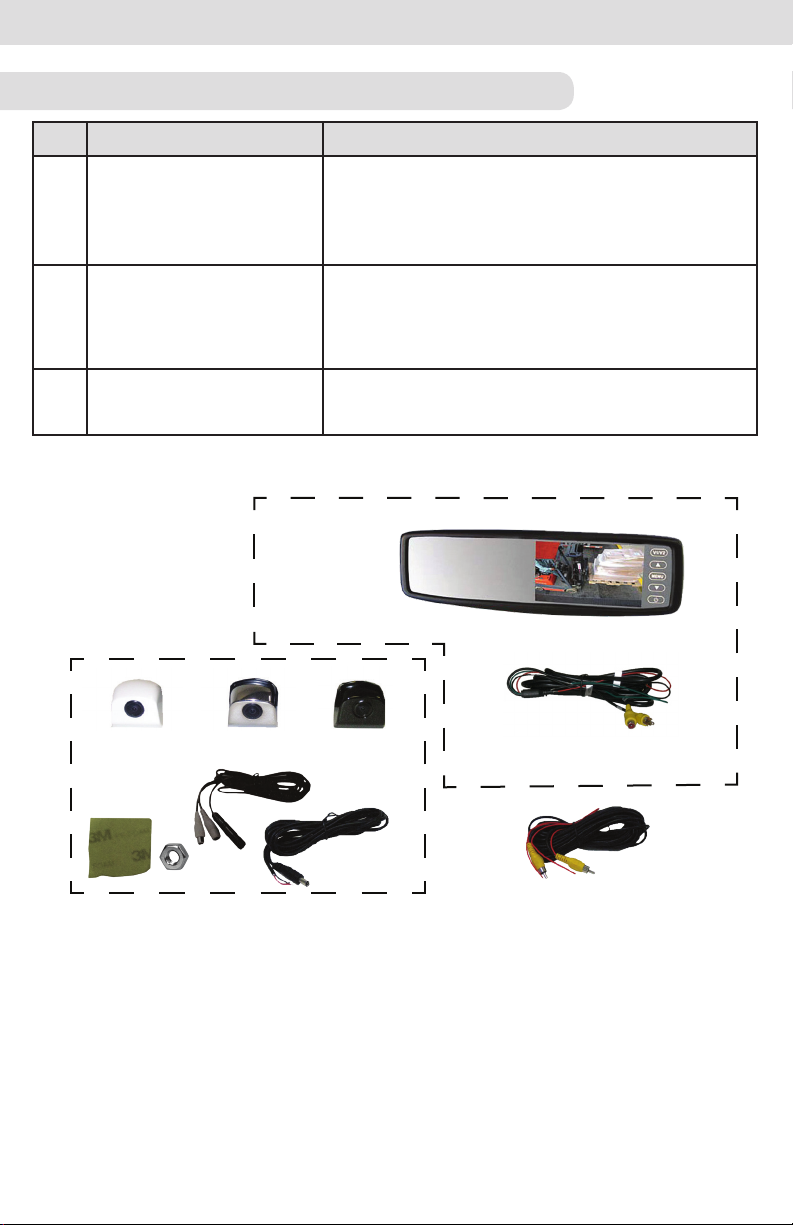
Component List ........................................................................................................3-4
How To Operate Display ..........................................................................................5
Wiring Diagram ........................................................................................................ 6-7
Camera Specifications ............................................................................................. 8
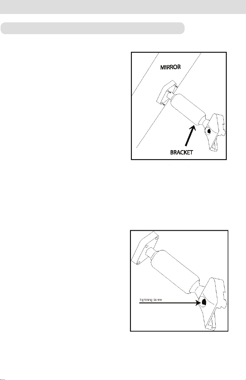
Rearview Mirror Installation ..................................................................................... 9
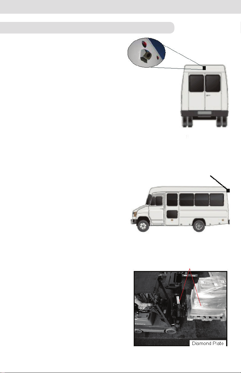
Camera Installation .................................................................................................. 10
Testing .......................................................................................................................11
Rosco Vision Systems introduces a revolutionary new backup camera system
for small to medium vehicles. MOR-VisionTM utilizes an interior rearview mirror
to display a 4.3” LCD monitor when the vehicle shifts into reverse. This monitor
allows the driver to see behind the vehicle for added convenience and safety.
The camera has an advanced CMOS lens sensor able to process excellent
images under dark and light conditions. The camera has a 170° diagonal field of
vision giving superb coverage behind the vehicle and complies with the latest
NHTSA 49 CFR Parts 571 and 585 (RIN 2127-AK43).
MOR-VISION™ REARVIEW MIRROR/MONITOR COMBO BACKUP CAMERA SYSTEM
General Technical Specifications:
Power Supply: 12VDC
Power Consumption: 1 Watt
Current Draw: <2000 mA
Video Input: composite video; 1 Vp-p@75 impedance
Operating Temp: -5°F to 150°F(-20°C to 65°C)
Monitor Dimensions: 11” W x 3” H x 1.5” D
1. Wire Tester 4. Wire Stripper 7. Drill
2. Phillips Screwdriver 5. Pencil 8. Tape
3. Tape Measure 6. Drill Bits
2