Wireless Kit For Backup Camera Systems STSW1001
NOTE!
Video and sound are sent from the transmitter module to the
receiver module. To ensure proper functioning, it is important
to check whether the wireless transmission is stable before final
installation.
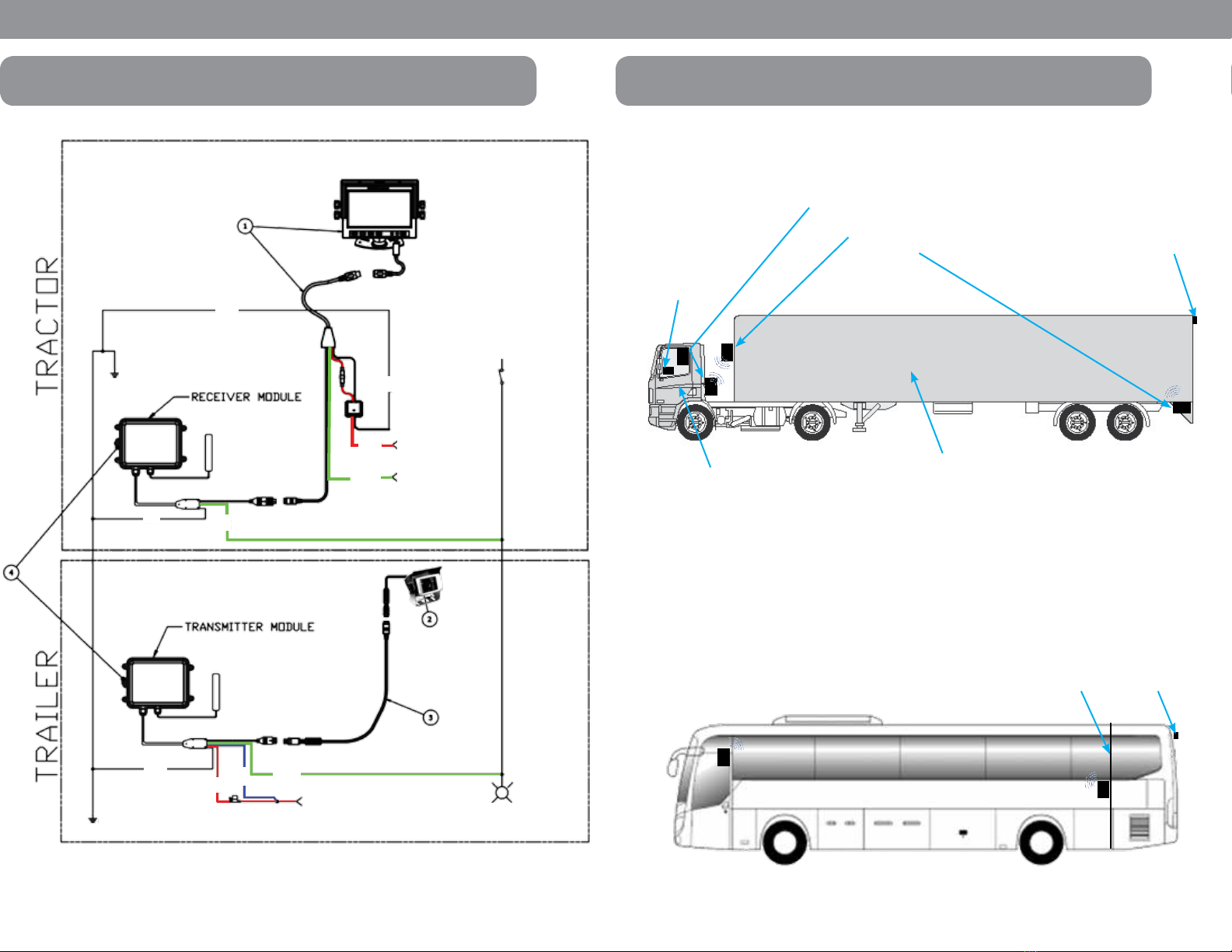
• Attach the modules temporarily to the planned installation location.
• Install the rear view video system if you have not already done so.
• Start up the rear view video system.
To do this, proceed as follows for each module:
Hold the module at the chosen location and mark the four points for
drill holes. Drill holes with a diameter of 5/32in (#21) at each of the
points you just marked. Screw the module on with #10-32 self-tapping
screws.
If the camera image transmission is stable (two or three reception bars at
the top right of the monitor), you can complete final installation of the two
modules. If faults occur (only one reception bar or a yellow warning triangle
on the top right of the monitor) turn or move the transmitter or receiver
module slightly and conduct further tests.
Fixing the antennas
NOTE!
Always align the antennas in the same direction, for example, both
vertically. This improves the transmission performance.
• You can glue the antenna on the corresponding module.
i
i
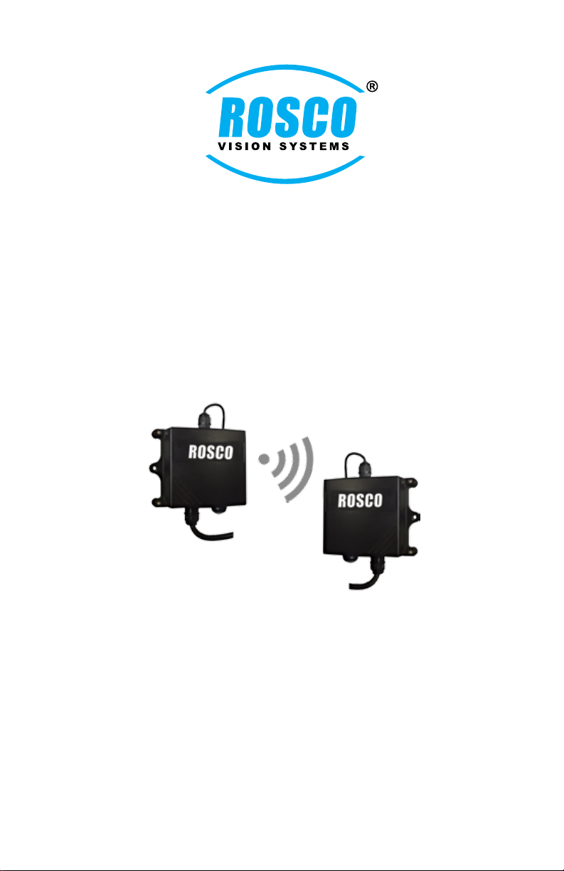
INSTALLATION
Attaching the modules
. . . . . . . . . . . . . . . . . . . . . . . . . . . . . . . . . . . . . . . . . . . . . . . . . . . . . . . . .
To test the installation, proceed as follows:
8
PAIRING - 3 OPTIONS
OPTION 1: Trailer with no reverse lights
This option is designated for a trailer source where no reverse lights are
present for connection of the Green wire.
Connect the red and blue wire from the transmitter module to constant
power (positive) and the green cable of both modules to the same switched
circuit; such as trailer lights/running lights. Connect both black wires to ground.
Switch on the monitor. Activate the required channel. Engage and disengage the
light switch three times within ten seconds (approx. two seconds between each
“on position”).
The LED on the transmitter module and the LED on the receiver module
flash red. The modules synchronize themselves with each other (takes about
3 - 5 seconds)
OPTION 2: Pairing the system with reverse gear
Connect the red and blue wire from the transmitter module to constant power
(positive) and the green cable of both modules on the reversing light circuit.
Connect both black wires to ground.
• Switch on the monitor.
• Activate the required channel.
• Engage and disengage the reverse gear three times within 10 s.
The LED on the transmitter module and the LED on the receiver module
flash red. The modules synchronize themselves with each other (takes about
3 to 5 seconds).
OPTION 3: Pairing the system manually with the pairing button
Connect the red and blue wire from the transmitter module to constant power
(positive) Connect black wire to chassis ground.
Connect black wire of reciever to ground. DO NOT CONNECT ANY GREEN
WIRES. Press the pairing button on the receiver module three times within 10s
(press the button approx. 1 time per second). The LED on the receiver module
flashes red. The monitor displays the message “Pairing Start” and a counter that
counts down 50s. You need to perform the pairing of the transmitter module
within 50s. Press the pairing button on the transmitter module three times within
10s (press the button approx. 1 time per second). The LED on the transmitter
module flashes red. The modules synchronize themselves with each other (takes
about 3 - 5 seconds).
The transmitter module and the receiver module have to be paired
with each other so that the monitor can display the camera images.
This is conducted at the factory.
NOTE!
. . . . . . . . . . . . . . . . . . . . . . . . . . . . . . . . . . . . . . . . . . . . . . . . . . . . . . . .
. . . . . . . . . . . . . . . . . . . . . . . . . . . . . . . . . . . . . . . . . . . . . . . . . . . . . . . .
9
i