MacDon M105 User manual

M105. M155, and M205 Drive Wheel Nut Installation For SPN D61, SPN E03 SPN E04, or E06
Safety Product Modification
1. Remove decal MD #166472 (220 ft-lbs) from the right
hand window of the windrower.
Figure 1 –Windrower R/H Window Decal
2. Apply decal MD #166575 (170 ft-lbs) in the same
location. Refer to the approximate dimensions in
Figure 2.
- 60 mm to the right of the R/H window hinge 160 mm
up from the R/H window hinge
Figure 2 –R/H Window Decal
Revision A Page 1of 4
Form 169

3. Place decal MD #166584 (170 ft-lbs) directly on top
of decal MD #166472 (220 ft-lbs) on both left hand
and right hand drive tires on both the inside and
outside of the rims.
Figure 3 –Drive Wheel Decal Location
Figure 4 –Old Drive Wheel Decal
4. Place decal MD #166454 to the right of each MD
#166584 decal as shown in Figure 5.
Figure 5 – New Drive Wheel Decal
MD #166584 And READ MANUAL
Decal MD #166454
Revision A Pa
g
e 2 of 4
Form 169

5. It is critical to ensure that the hardware is L9.
Verify as follows:
- Verify nut is L9 by ensuring it has 9 marks on one
side (See Figure 6)
- Verify washer is L9 by ensuring it has “L9” stamped
on one side (see Figure 6)
6. Mark each wheel stud at the 12 o’clock position.
Remove the old nuts ONE AT A TIME and replace
with new washer and nut as per Step 7 and 8 ONE
AT A TIME in the numbered sequence shown on the
new drive wheel decal (Figure 7).
Check to see if the mark on the stud moves when the
nut is being removed. If the mark and stud are
moving, replace the wheel bolt.
7. Inspect the threads on each stud for damage. Spin on
nut only, by hand to check entire thread length to the
wheel rim. Remove nut, If thread damage is evident,
replace the wheel bolt.
For Auburn Gear drive wheels, use MD #49880
Wheel Bolt 5/8”NF x 60LG.
8. Inspect wheel bolt hole on the rim (that hole is
concentric around bolt) to see if there is any
elongation or wallowing out or other obvious damage.
If there is no damage replace old nut with the new
hardened washer and L9 nut. Thread the nut on using
hand tools only until they meet the washer. Nut
should be installed dry. Do not lubricate threads
with oil or products such as Never Seez®.
Tighten to 170 ft-lbs (230 Nm).
9. After inspecting wheel bolt holes, if multiple holes are
damaged this is an indication wheel bolt clamping
force was compromised. Replace the wheel rim and
all 8 wheel bolts. When (if) replacing wheel bolts, add
a couple of drops of a retaining compound such as
Loctite® 609TM to the knurled shoulder only, of the
new wheel bolt. Insert bolt till knurled shoulder
engages power wheel bolt hole engaging previous
knurling marks. Tap bolt in to seat head flush with
hub.
10. Along with new L9 hardware, it is important to adhere
to the new torque procedure as shown on the new
decal in Figure 7.
After all nuts are replaced, re-torque the new nuts to
170 ft-lbs (230 Nm) in the numbered sequence
shown on the decal.
DO NOT OVERTORQUE. Doing so may cause
damage to the stud.
Figure 6 –Nut And Washer Identification
Figure 7 – New Drive Wheel Decal With New
Torque Specification
Figure 8 – New L9 Nut And Washer
Form 169847 Revision A Pa
g
e 3 of 4

166590 MD KIT ENGLISH
PART NO DESCRIPTION QTY
136632 NUT - HEX L9 5/8-18-L9-ZP 16
136633 WASHER - FLAT HARDENED 5/8 IN. NOMINAL (L9) 16
169847 INSTRUCTION - SPM D61 SB1361 WHEEL NUTS & WASHERS 1
169570 INSTRUCTION - QUICK CARD M105 1
169565 INSTRUCTION - QUICK CARD M155 1
169475 INSTRUCTION - QUICK CARD M205 1
166575 DECAL - BOLT TORQUE 1
166584 DECAL - BOLT TORQUE 4
166454 DECAL - READ MANUAL 4
Inserting Supplemental Pages Into Customer’s Existing Manuals
Remove printed package from shrink wrap.
The package has information for M105, M155 and M205.
Depending on which unit you are working on, pull the appropriate model-specific information from
the package and discard the rest.
The information consists of:
- Pages destined for the Op Manual
- Pages destined for the Parts Catalog
Insert the new pages into the existing Op Manual and Parts Catalog.
Trim page to fit book and tape or glue over existing page.
NOTE: At the beginning of each section is a page reference table to help find the appropriate
section in the books for the new pages.
Quick Card
Each Model Windrower has a specific Quick Card for it. Leave the appropriate model Quick Card
in the cab for quick reference. Discard Quick Card that does not apply to the unit you are
updating.
NOTE: This form contains pages intended to be cut out and inserted into
customers existing manuals as noted above.
Revision A Pa
g
e 4 of 4
Form 169

M105
Self-Propelled Windrowe
r
Supplement to Operator’s Manual
L
169552_SUPPLEMENT Rev.
D


MAINTENANCE AND SERVICING
169552_Supplement Revision D Page 3 of 8
7.4.2 Break-In Inspections
ITEM SEE SECTION
1 Hour Check Drive Wheel Nut Torque - 170 ft·lbf (230 N·m).
Repeat Checks Every Hour Until Torque Stabilizes. 7.12.1.2
At
5 Hours
Check A/C Belt Tension. 7.8.10.1
Check Caster Wheel Nut Torque - 120 ft·lbf (163 N·m). 7.12.2.3
Check Caster Wheel Anti-Shimmy Dampener Bolt Torque.
Inboard Bolts - 100 ft·lbf (135 N·m).
Outboard Bolts - 85 ft·lbf (115 N·m).
7.12.2.6
Check Walking Beam Width Adjustment Bolts Torque - 330 ft·lbf (448 N·m). 6.3.6
At
10 Hours
Check Walking Beam Width Adjustment Bolts Torque - 330 ft·lbf (448 N·m). 6.3.6
Check NEUTRAL Adjustment. See Dealer.
At
50 Hours
Check Hose Clamps - Air Intake / Radiator / Heater / Hydraulic.
Hand-tighten unless otherwise noted. Various
Check Walking Beam Width Adjustment Bolts Torque - 330 ft·lbf (448 N·m). 6.3.6
Check Caster Wheel Anti-Shimmy Dampener Bolt Torque.
Inboard Bolts - 100 ft·lbf (135 N·m).
Outboard Bolts - 85 ft·lbf (115 N·m).
7.12.2.6
Change Drive Wheel Lubricant. 7.12.1.3
Change Hydraulic Oil Filters. 7.11.3
Use this table instead of the one provided
on page 122 in the original manual.
Replaces Page 122 in M105 Op Manual
122

MAINTENANCE AND SERVICING
169552 / 169554 184 Revision D
7.12 WHEELS AND TIRES
7.12.1 Drive Wheels
7.12.1.1 Tire Inflation
a. Visually check daily that tires have not lost
pressure. Under-inflation of drive tires can cause
side wall cracks.
DANGER
To avoid severe personal injury or death
caused by machine runaway, shut off
engine, and remove key before performing
any of the following checks and/or
adjustments.
b. Measure tire pressure annually with a gauge.
Maintain the pressure as follows:
1. Determine tire size and type that is installed
on your machine.
2. See Section 4.2 SPECIFICATIONS to
determine recommended tire pressure.
3. Adjust tire pressure as required.
DANGER
•NEVER install a tube in a cracked wheel
rim.
•NEVER weld a wheel rim.
•Make sure all the air is removed from a
tire before removing the tire from the rim.
•NEVER use force on an inflated or
partially inflated tire. Make sure the tire is
correctly seated before inflating to
operating pressure.
•Do NOT remove, install or make repairs
to a tire on a rim unless you have the
proper equipment and experience to
perform the job. Take the tire and rim to a
qualified tire repair shop.
•If the tire is not correctly located on the
rim, or if too full of air, the tire bead can
loosen on one side, causing air to leak at
high speed and with great force. An air
leak of this nature can thrust the tire in
any direction, endangering anyone in the
area.
•Do NOT exceed maximum inflation
pressure as per label on tire.
•Use a safety cage if available.
•Do NOT stand over tire. Use a clip-on
chuck and extension hose.
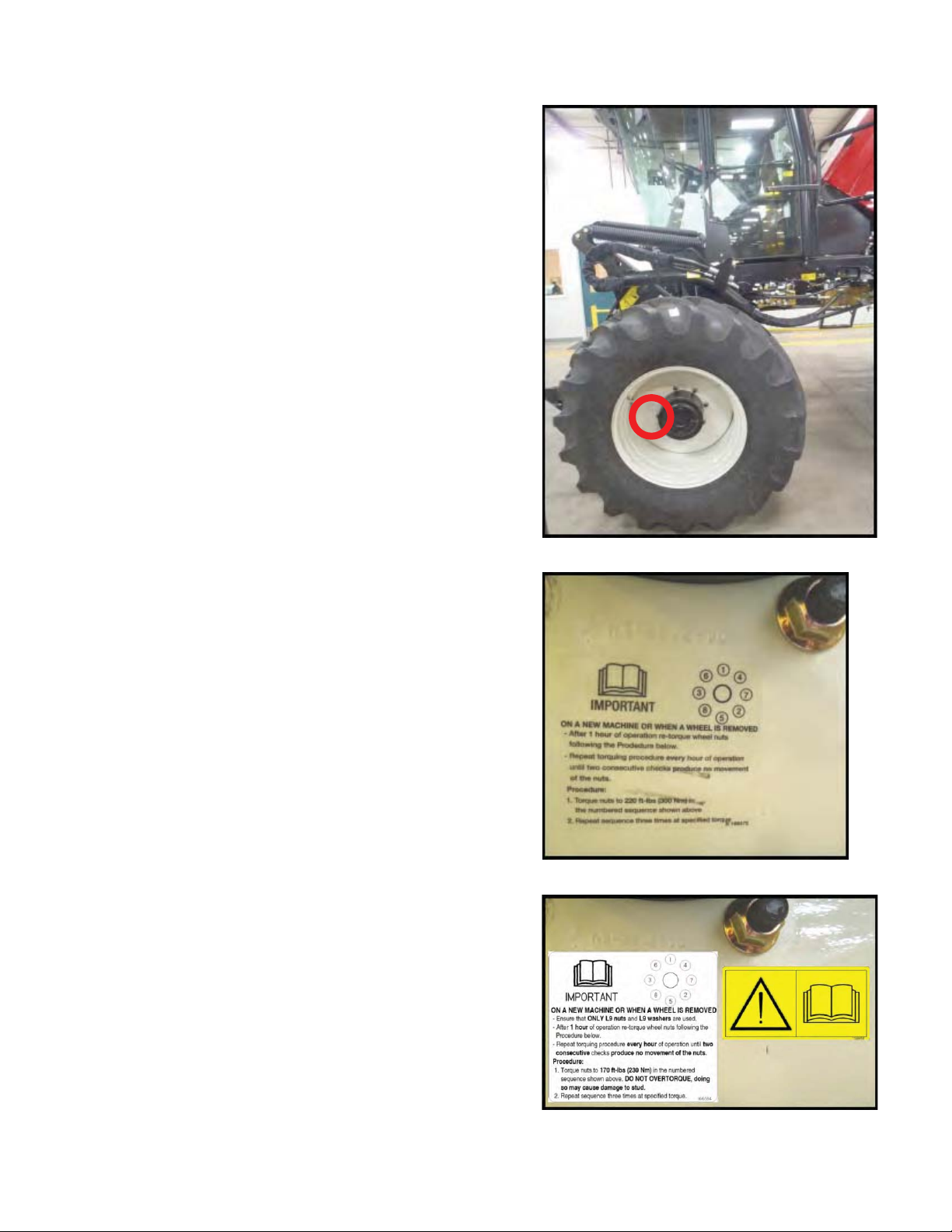
7.12.1.2 Wheel Nut Torque
At first use, or when a wheel is removed, re-
torque drive wheel nut torque after one hour of
operation.
Continue with torquing procedure at one hour
intervals of operation until two consecutive
checks produce no movement of the nuts.
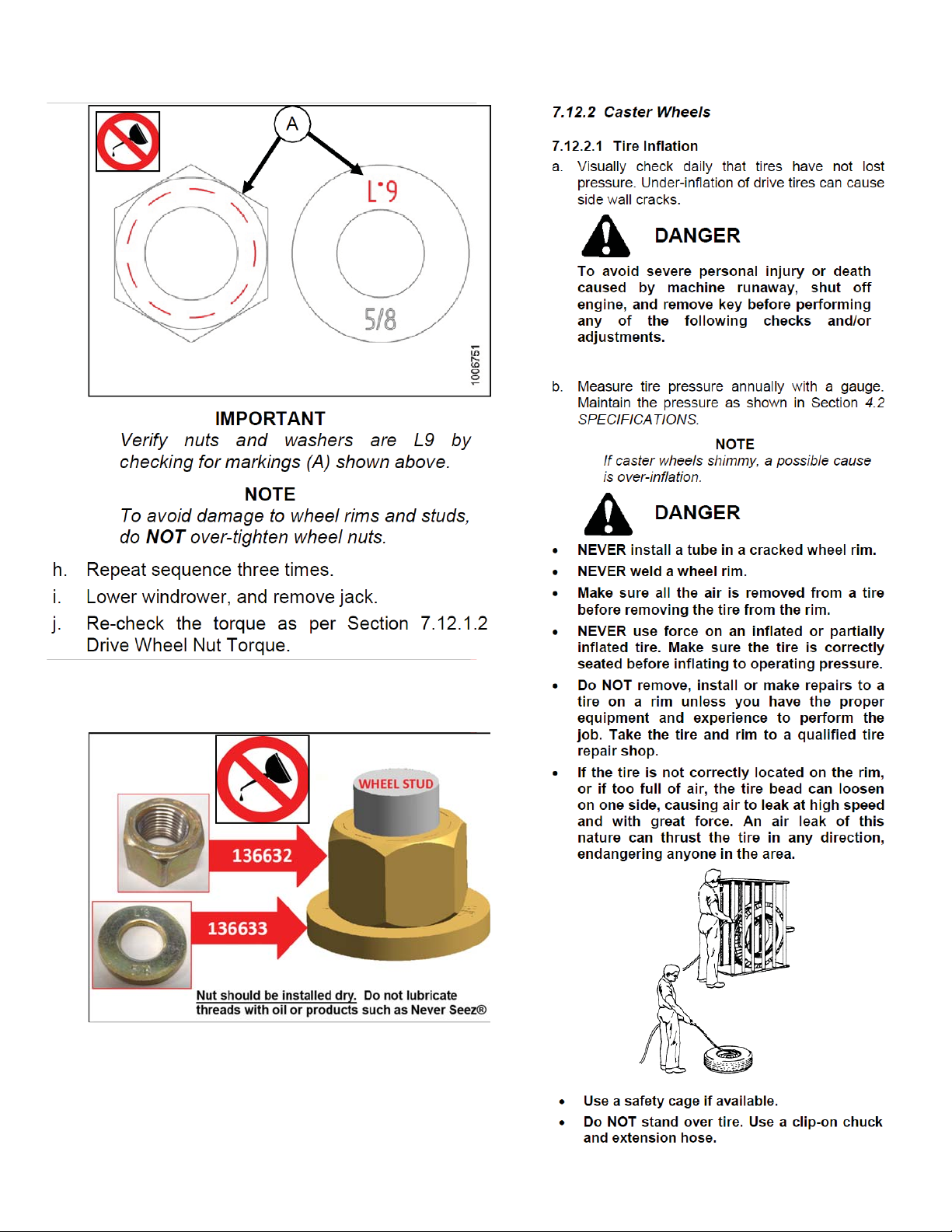
a. Tighten nuts to 220 lbf·ft (300 N·m) using the
tightening sequence as shown above.
NOTE
To avoid damage to wheel rims, do NOT
over-tighten wheel nuts.
b. Repeat sequence three times.
1
5
3
7
8
2
4
6
•
Replaces Page 184 in M105 Op Manual

MAINTENANCE AND SERVICING
169552_Supplement Revision D Page 7 of 8
7.12.1.4 Drive Wheel Removal/Installation
DANGER
To avoid severe personal injury or death
caused by machine runaway, shut off
engine, and remove key before performing
any of the following checks and/or
adjustments.
CAUTION
Header MUST be remove
d, and NO weight
box installed. Use a hydr
aulic jack with
minimum lifting capacity of 5000 lb
(2268 kg) to provide adequate support fo
r
the machine.
a. Remove header.
b. Park windrower on level ground, and block all
wheels.
c. Place Ground Speed Lever (GSL) in N-
DETENT, shut down engine, and remove key.
d. Jack up windrower under leg jack point, and
raise windrower wheel slightly off ground.
e. Undo wheel nuts, and remove wheel.
NOTE
To install new tire, ensure that air valves
are on the outside, and tire tread points
forward.
NOTE
For Turf tires (diamond tread), be sure
arrow on sidewall points in forward
rotation.
f. Place wheel on hub.
(continued next page)
Follow this procedure instead of the one
provided on page 186 in the original
manual.
186
Replaces Page 186 in M105 Op Manual

MAINTENANCE AND SERVICING
Page 8 of 8
g. Install L9 nuts and L9 washers, and tighten to
170 ft·lbf (230 N·m) using the tightening
sequence as shown above.
IMPORTANT
Verify nuts and washers are L9 by
checking for markings (A) shown above.
NOTE
To avoid damage to wheel rims and studs,
do NOT over-tighten wheel nuts.
h. Repeat sequence three times.
i. Lower windrower, and remove jack.
j. Re-check the torque as per Section 7.12.1.2
Drive Wheel Nut Torque.
A
/VUTTIPVMECFJOTUBMMFEESZ
187
Replaces Page 187 in M105 Op Manual 187
Replaces Page 187 in M105 Op Manual

M105
Self-
Propelled Windrower
PARTS CATALOG
Part #169549 Rev. D
Original Instruction
SUPPLEMENT
_

Form # 169549/ 169550/ 169551 Revision D
22
DRIVE WHEELS AND TIRES
SUPPLEMENT

Form # 169549/ 169550/ 169551 Revision D
23
DRIVE WHEELS AND TIRES
REF PART
NUMBER DESCRIPTION QTY SERIAL
NUMBER
B4632 Kit - Drive Tires - TURF 23.1-26 ........................................................... See note 1
1 111699 WHEEL 26DW-20L C/W DECALS........................................................ 2
2 111695 TIRE 23.1 X 26 R3 10 PLY................................................................... 2
3 112475 STEM.................................................................................................... 2
4 135611 PLUG – VALVE STEM ......................................................................... 2
B4944 Kit - Drive Tires - BAR 600-65 R28....................................................... See note 1
1 162019 WHEEL - 28 X 18 C/W DECALS .......................................................... 2
2 162022 TIRE – 600-65 R28 BAR TREAD.......................................................... 2
3 112475 STEM-VALVE (METAL)........................................................................ 2
B4634 Kit - Drive Tires - TURF 18.4-26 ........................................................... See note 1
1 162295 WHEEL 26DW-16L C/W DECALS & VALVE STEMS (reversible)....... 2
2 163601 TIRE-18.4 X 26 R3, TURF.................................................................... 2
3 112475 STEM-VALVE (METAL)........................................................................ 2
4 135611 PLUG – VALVE STEM.......................................................................... 2
5 162435 SPUD – WHEEL ................................................................................... 2
B4633 Kit - Drive Tires – BAR 18.4-26............................................................ See note 1
1 162295 WHEEL 26DW-16L C/W DECALS & VALVE STEMS (reversible)....... 2
2 111694 TIRE 18.4 X 26 R1 - BAR .................................................................... 2
3 112475 STEM-VALVE (METAL)........................................................................ 2
4 135611 PLUG – VALVE STEM.......................................................................... 2
5 162435 SPUD – WHEEL ................................................................................... 2
B5506 Kit - Drive Tires - TURF 580-70R26...................................................... See note 1
1 111699 WHEEL 26DW-20L C/W DECALS........................................................ 2
2 162431 TIRE - 580-70R26, TURF RADIAL ....................................................... 2
3 112475 STEM-VALVE (METAL)........................................................................ 2
4 135611 PLUG – VALVE STEM ......................................................................... 2
A 136632 NUT - HEX L9 5/8–18–L9–ZP
B 136633 WASHER - FLAT HARDENED 5/8/IN. NOMINAL (L9)
NOTE: 1. Kits available through Whole Goods only.
SUPPLEMENT

Form # 169549/ 169550/ 169551 Revision D
84
DRIVE WHEEL MOTOR ASSEMBLY – BOLTED FRAME
SUPPLEMENT

Form # 169549/ 169550/ 169551 Revision D
85
DRIVE WHEEL MOTOR ASSEMBLY – BOLTED FRAME
REF PART
NUMBER DESCRIPTION QTY SERIAL
NUMBER
1 162241 MOTOR-WITH SPEED SENSOR......................................................... 1
162230 MOTOR WITHOUT SPEED SENSOR ................................................. 1
2 162237 GUARD-SENSOR................................................................................. 1
3 112184 FITTING - ADAPTER HYD ................................................................... 2
4 111693 HOSE-HYDRAULIC.............................................................................. 2
5 162236 DRIVE- WHEEL AUBURN 41.42:1....................................................... 2
6 111266 PLATE - WHEEL DRIVE....................................................................... 2
8 30970 FITTING - ELBOW 90° HYD................................................................. 4
9 30045 O-RING................................................................................................. 2
10 135641 FITTING - ELBOW 90° HYD................................................................. 2
11 30282 FITTING - ELBOW 90° HYD................................................................. 4
12 162085 HOSE-HYD........................................................................................... 4
13 112939 SLEEVE- TRACTION HOSE ................................................................ 4
14 49227 FASTENER-CABLE TIE GREEN ......................................................... 5
15 40701 FASTENER-CABLE TIE-YELLOW (located at pump).......................... 3
16 21763 FASTENER - CABLE TIE BLACK ....................................................... 1
17 40702 FASTENER-CABLE TIE RED (located at pump).................................. 3
18 49232 FASTENER-CABLE TIE WHITE (located at pump).............................. 3
19 135266 FASTENER - CABLE TIE LIGHT BLUE............................................... 2
A 112128 BOLT - HEX HD .750-1L UNF X 2.75
B 18638 WASHER - REG. LOCK 1/2 IN. NOM. ID ZP
C 21575 BOLT - HH 1/2 NC X 1.0 LG GR 5 ZP
E 21582 BOLT - HH 5/8 NC X 1.75 LG GR5 ZP
F 112130 WASHER - HARDENED
G 18666 NUT-HEX LOCK DT 5/8-11 UNC ZP
H 136632 NUT - HEX L9 5/8–18–L9–ZP
J 136016 BOLT-HEX HD 3/4-10UNC X 2.25 IN. LG
K 18689 NUT - HEX LOCK DT .750-10UNC
L 136027 WASHER- HARDENED
M 135376 BOLT - SKT HD 1/2 NC X 2.00 LG GR. 8
N 136633 WASHER - FLAT HARDENED 5/8/IN. NOMINAL (L9)
SUPPLEMENT

Form # 169549/ 169550/ 169551 Revision D
116
INFORMATION DECALS & REFLECTORS
SUPPLEMENT

Form # 169549/ 169550/ 169551 Revision D
117
INFORMATION DECALS & REFLECTORS
PAINT
135148 PAINT - black, spray can (55 – 65 Gloss Level) (was 25990)
25991 PAINT - black, 1 litre (55 – 65 Gloss Level)
23950 PAINT - red, spray can (To be used for small touch ups only)
49832 PAINT – red, 1 US Quart. See note (1).
49833 ACTIVATOR – for paint, 1 US Pint.
49834 REDUCER – for paint, 1 US Quart.
49835 ACCELERATOR – for paint, 1 US Pint. See note (2).
32879 PAINT - white, spray can
23957 PAINT-white, 1 litre
NOTES: 1. When ordering 49832 red paint, also order part numbers 49833 and 49834. These three parts (Paint, Activator and
Reducer) must be premixed at a ratio of 2:1:1 respectively. This paint when mixed provides 2 sprayable quarts,
which is approximately enough for one engine hood. Further instructions supplied with paint.
2. Part 49835 is a paint accelerator. Adding approximately ½ to1 oz. of accelerator per sprayable quart will speed up
dry time. If paint accelerator is not added, there will be no change to paint, other than length of dry time.
REF PART
NUMBER DESCRIPTION QTY SERIAL
NUMBER
1 23165 DECAL – 50 HR LUBE
2 109842 DECAL – IMPORTANT
3 109205 DECAL – AUXILIARY POWER
5 160369 DECAL - LIGHTS
6 160320 DECAL-GROUND SPEED
7 160321 DECAL-SWITCH PANEL
8 166281 DECAL – HYDRAULIC OIL
11 109206 DECAL – JACK HERE
12 109207 DECAL – TIE DOWN
13 32070 DECAL - PATENTS
14 166575 DECAL – BOLT TORQUE
15 111221 DECAL – TIRE PRESSURE
16 134069 DECAL – COOLANT SYSTEM
17 183336 DECAL – FUSE BLOCK
18 160108 DECAL - CONTROL
19 110987 DECAL - REFRIGERANT/OIL
20 110988 DECAL - ENGINE OIL
21 24769 DECAL – DIESEL FUEL ONLY
22 160332 DECAL-IGNITION
23 115147 REFLECTOR-RED.
115145 REFLECTOR - FLRSCNT RED-ORANGE
115146 REFLECTOR - amber
25 101375 DECAL – torque wheel bolts (10x16 casters only)
26 166273 DECAL – battery master disconnect
27 139723 DECAL – latch handle
28 166576 DECAL-BOLT TORQUE
29 166509 DECAL-AIR COND DYE
30 166454 DECAL – READ MANUAL
Note: For Russian language decals, see pages 136, 137
SUPPLEMENT

THIS PAGE INTENTIONALLY BLANK

The harvesting specialists worldwide.
M155
Self-Propelled Windrower
Supplement to Operator’s Manual
169563_SUPPLEMENT Rev. D
Original Instruction

1 Supplement to Operator's Manual
Issued November 28, 2013
This supplement contains important updates to the information in your M155 Self-Propelled Windrower Operator’s
Manual. It is vital that you are aware of and use this new information.
Insert the attached pages into the manual as follows:
Topic title Page reference in original manual
Tightening Drive Wheel Nuts 367
Installing Drive Wheel 369–370
Lowering Drive Wheel 370
Break-in Inspections 380
169563_SUPPLEMENT 1Rev. D
Other manuals for M105
4
This manual suits for next models
2
Table of contents
Other MacDon Farm Equipment manuals

MacDon
MacDon D1X Series User manual

MacDon
MacDon HC10 Guide

MacDon
MacDon D65 User manual

MacDon
MacDon FD75 User manual

MacDon
MacDon D1X Series User manual

MacDon
MacDon M155E4 User manual

MacDon
MacDon R113 User manual

MacDon
MacDon R113 User manual

MacDon
MacDon 2000-B User manual

MacDon
MacDon A40-D User manual
Popular Farm Equipment manuals by other brands

Schaffert
Schaffert Rebounder Mounting instructions

Stocks AG
Stocks AG Fan Jet Pro Plus 65 Original Operating Manual and parts list

Cumberland
Cumberland Integra Feed-Link Installation and operation manual

BROWN
BROWN BDHP-1250 Owner's/operator's manual

Molon
Molon BCS operating instructions

Vaderstad
Vaderstad Rapid Series instructions