sitrex QRX 12 Quick setup guide

ASSEMBLY, USE AND MAINTENANCE
QRX 12/14
201600


1
INDEX
SECTION 1 GENERAL INFORMATION ____________________________________________________2
1.1 WARRANTY ___________________________________________________________________2
SECTION 2 GUIDE TO THE SIGNS AND SYMBOLS USED____________________________________3
2.1 SIGNS AND SYMBOLS __________________________________________________________3
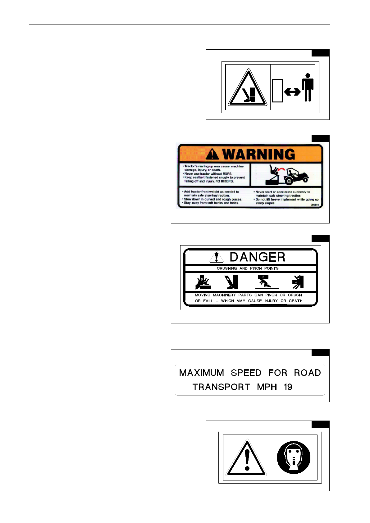
2.2 WARNING SIGNS _______________________________________________________________3
2.3 WARNINGS IN THE MANUAL _____________________________________________________5
2.4 INDICATION SIGNS _____________________________________________________________5
SECTION 3 TECHNICAL SPECIFICATIONS ________________________________________________6
3.1 MACHINE TECHNICAL SPECIFICATIONS ___________________________________________6
3.2 CHARACTERISTICS OF HYDRAULIC/ELECTRIC COMPONENTS________________________6
3.3 MACHINE IDENTIFICATION ______________________________________________________7
3.4 MACHINE IDENTIFICATION DATA _________________________________________________8
SECTION 4 ASSEMBLY ________________________________________________________________9
4.1 DELIVERY AND UNPACKING._____________________________________________________9
4.2 ASSEMBLY INSTRUCTIONS _____________________________________________________10
4.3 METRIC–INCHES CONVERSION TABLE ___________________________________________11
4.4 MACHINE ASSEMBLY __________________________________________________________12
4.5 HYDRAULIC SYSTEM ASSEMBLY ________________________________________________21
4.6 ELECTRICAL SYSTEM ASSEMBLY _______________________________________________28
4.7 CENTER RAKE WHEEL KIT (OPTIONAL)___________________________________________29
4.8 ASSEMBLY OF CONVERSION KIT FROM QRX12 TO QRX14 __________________________33
4.9 GREASING POINTS ____________________________________________________________35
SECTION 5 ADJUSTMENT, PREPARATION AND USE ______________________________________36
5.1 HITCHING THE MACHINE TO THE TRACTOR_______________________________________36
5.2 UNHITCHING THE MACHINE FROM THE TRACTOR _________________________________37
5.3 ELECTRIC SELECTOR _________________________________________________________38
5.4 ROAD TRANSPORT ____________________________________________________________41
5.5 COMPLIANCE WITH THE HIGHWAY CODE_________________________________________43
5.6 WORKING POSITION ___________________________________________________________43
5.7 ADJUSTING THE PRESSURE OF THE RAKE WHEELS ON THE GROUND _______________44
5.8 WORKING POSITION ADJUSTMENTS. ____________________________________________45
5.9 WORKING ON ONE SIDE ONLY __________________________________________________46
5.10 Locking the rake wheel arms in the raised position_____________________________________48
SECTION 6 GENERAL INSTRUCTIONS FOR MAINTENANCE ________________________________49
6.1 REPAIR WORK ________________________________________________________________49
6.2 STORAGE FOR LONG PERIODS _________________________________________________49
6.3 MAINTENANCE INSTRUCTIONDS ________________________________________________50
6.4 TIRES _______________________________________________________________________50
6.5 HYDRAULIC CIRCUIT __________________________________________________________50
6.6 SCRAPPING THE MACHINE _____________________________________________________51

2
SECTION 1 GENERAL INFORMATION
1.1 WARRANTY
When the machine is received, check to make sure that it has not been damaged during shipping and that all
the accessories are present. Claims must be made to the sales agent in writing within 8 days from receipt.
The manufacturer warrants new machinery to be free from defects in materials and workmanship at the time
of delivery to the original purchaser if correctly set up and operated according to this Operator's Manual.
The manufacturer will repair or replace free of charge any defective part which is returned by the purchaser
(freight prepaid) and found to be defective on inspection authorized by the manufacturer during the warranty
period.
This warranty shall be valid for 12 (twelve) months from the delivery of the goods to the original purchaser.
If the customer is unable to return the defective part to the manufacturer, the manufacturer cannot be held
liable for any costs due for repair or replacement of any part of the machine. The manufacturer shall only
supply the part(s) required for such repair and/or replacement.
The warranty shall be considered null and void when it is evident that the machine has been improperly used
or has been repaired without authorization.
The manufacturer shall not be held liable for any obligation or agreement reached by any employers, agents
or dealers who do not comply with the above warranty. The manufacturer cannot be held liable for the sub-
sequent damages. This warranty replaces any other warranty, either explicit or implied, as well as any other
obligation of the manufacturer.
NOTE:
ALL WORK UNDER WARRANTY OR REPLACEMENTS MUST BE APPROVED BY THE MANUFACTURER BEFORE
WORK BEGINS.
ANY WORK OR REPAIRS MADE BEFORE BEING SEEN AND APPROVED BY THE MANUFACTURER WILL NOT BE
COVERED UNDER WARRANTY
PLEASE NOTIFY YOUR SALES & SERVICE DEPARTMENT OF THIS POLICY.

3
SECTION 2 GUIDE TO THE SIGNS AND SYMBOLS USED
2.1 SIGNS AND SYMBOLS
These signs and symbols give information to the operator on how to make the best use of the machine so as
to prolong its life, avoid damage, optimize work and, above all, to avoid injury to the operator and anyone
within range of the machine.
2.2 WARNING SIGNS
Fig. 2.1
Read carefully the user’s manual and follow all the safety
instructions.
Fig. 2.2
Before doing any checking, maintenance and/or repair op-
erations, stop in a suitable place, turn off the tractor, apply
the brake, remove the key from the ignition and consult
this manual.
Fig. 2.3
Warns against the potential and serious risk of crushing
your hands. Keep at a safe distance.
2
.
1
2
.
2
2
.
3

4
Fig. 2.4
Warns against the potential and serious risk of injury to the
feet. Keep at a safe distance.
Fig. 2.5
Warns against the potential and serious risks
for the driver and/or other persons who are
riding improperly on the tractor and/or on the
machine.
Fig. 2.6
Summarizes all the potential and serious
dangers encountered during the assembly,
use, maintenance and/or repair of the ma-
chine.
Fig. 2.7
Indicates the maximum speed allowed during
road transport (19 MPH - 30 Km/h).
Fig. 2.8
Recommends the wearing of suitable protective equipment
and clothing to prevent injury when carrying out assembly,
use, maintenance and repair operations.
2
.
4
2
.
5
2
.
6
2
.
7
2
.
8

5
2.3 WARNINGS IN THE MANUAL
Fig.2.9
Indicates an imminently hazardous situation which,
if not avoided, could result in death or serious per-
sonal injury.
Fig.2.10
This indicates a potential hazard that, if not avoided,
could result in serious personal injury. It also warns
not to remove protective devices.
2.4 INDICATION SIGNS
Fig. 2.11
Indicates the components to be assembled
and/or identified on the right or left side of the
machine (Fig.4.1). The RH and LH sides are
determined by standing behind the machine
and looking forward.
Fig.2.12
Indicates a greasing point.
2
.
9
2
.
10
2
.
12
RIGHT LEFT
2
.
11

6
SECTION 3 TECHNICAL SPECIFICATIONS
3.1 MACHINE TECHNICAL SPECIFICATIONS
MODEL QRX 12 QRX 14
Rake Wheels 12 14
Rake Wheel Diameter 55" (1.4m) 55" (1.4m)
Rake Wheel Diameter (optional) 60" (1.52m) 60" (1.52m)
Maximum Windrow Width (F) 6' 7" (2m) 6' 7" (2m)
Minimum Windrow Width (F) 3' (0.9m) 3' (0.9m)
Maximum Working Width (E) 25' 1" (7.65m) 28' (8.5m)
Minimum Working Width (E) 21'12" (6.7m) 24'11" (7.6m)
Minimum Transport Height (B) 9'2" (2.8m) 9'2" (2.8m)
Tractor Requirements HP 50 (36.7 KW) HP 60 (44 KW)
Tires 205-75/15 205-75/15
Transport Width (C) 9'2" (2.8m) 9'2" (2.8m)
Transport Length (A) 23'9" (7.24m) 26'5" (8.04m)
Tread Width (D) 8'1½" (2.48m) 8'1½" (2.48m)
Weight * 2855 lbs - 1295 kg 3240 lbs - 1470 kg
*Full optional
3.2 CHARACTERISTICS OF HYDRAULIC/ELECTRIC COMPONENTS
Power supply: 12 V DC 7-pin connector ISO1185 (3-pin connector DIN9680 on request, see fig.5.6)
Characteristics of solenoid valve coils: 12 V DC – 60 Watt
Fuse 5 A
Working pressure of hoses, fittings, cylinders etc. : 200 bar – 2800 psi
A
D
C
B
E
F

7
1
3
4
4
7
8
5
12
11
9
10
15
1
3
1
6
6
1
4
2
17
3.3 MACHINE IDENTIFICATION
1) INCLINED DRAWBAR
2) HITCH
3) PARKING STAND
4) HORIZONTAL DRAWBAR
5) LEFT FOLD-UP CYLINDER
6) LEFT FOLD-UP ARM
) LEFT TELESCOPING ARM
8) LEFT TANDEM WHEEL AXLE
9) LEFT REAR SECTION
10) LEFT CENTR. SECTION
11) LEFT FRONT SECTION
12) LEFT EXTENSION SECTION
13) LEFT RAKE WHEEL ARM
14) LEFT RAKE WHEEL
15) LEFT SPECIAL RAKE WHEEL ARM
16) CENTER RAKE WHEEL KIT (optional)
1 ) SPRING ASSEMBLY
3
.
1

8
3.4 MACHINE IDENTIFICATION DATA
The machine is identified by the following data:
•Machine type
•Serial number
•Year of manufacture
•WEIGHT
stamped on the nameplate attached to the machine frame and to be specified when requesting spare parts
or information.
Optional
Center rake wheel kit
Spa

9
SECTION 4 ASSEMBLY
4.1 DELIVERY AND UNPACKING.
The machine is delivered partially assembled in n 1 crate which also contains n° 6 cardboard boxes.
The rake wheels shipped are in separated pallet.
The cardboard boxes contain all the various accessories for assembly (pins, screws, fittings, etc.). The small
box not marked with a letter contains the reflector triangle to be attached to the machine.
All components are inspected by the manufacturer before shipment. Upon receipt of the machine, check that
the crate is intact and that the contents have not been damaged during shipment. If any damage and/or ir-
regularities are found, report them immediately to your dealer.
Note: The packaging is made from wood, plastic film, cardboard and steel, and must be dis-
posed of according to applicable laws in your locality.
Handle the crates received using lifting devices suitable for lifting the weight indicated and for providing sta-
bility for the crates and pallets in consideration of their size and shape.

10
4.2 ASSEMBLY INSTRUCTIONS
Examples of general measurements for identifying the assembly accessories based on type (Fig. 4.1)
For tightening torques, see the table below (the class of the material is normally stamped on the head of the
bolts). (Fig. 4.2)
4
.
1
4
.
2

11
Assembly must be done carefully and accurately, for the safety of the person(s) doing the as-
sembling and to ensure proper machine operation.
Assembly should be done on a flat, solid surface, using the proper tools and wearing suitable
clothing, making sure that all people not involved in the assembly are kept at a safe distance.
Assemblers must provide suitable lifting mechanisms and supports for stabilizing the partially
assembled units, so as to prevent them from falling and causing damage or injury. The steps for
assembly are illustrated in following. Depending on the experience of the assemblers and the
tools available, it is not necessary that the instructions be followed in the exact order shown
here, but the safety precautions described above must always be strictly and carefully followed.
4.3 METRIC–INCHES CONVERSION TABLE
mm inches mm inches mm inches mm inches
11/32" 26 1"1/64 55 2"5/32 300 11"51/64
25/64" 27 1"1/16 60 2"23/64 350 13"49/64
37/64" 28 1"3/32 65 2"35/64 400 15"47/64
45/32" 29 1"9/64 70 2"3/4 450 17"45/64
53/16" 30 1"11/64 75 2"15/16 500 19"43/64
615/64" 31 1"7/32 80 3"9/64 550 21"41/64
717/64" 32 1"1/4 85 3"11/32 600 23"39/64
85/16" 33 1"19/64 90 3"17/32 650 25"37/64
911/32" 34 1"21/64 95 3"47/64 700 27"35/64
10 25/64" 35 1"3/8 100 3"59/64 750 29"33/64
11 27/64" 36 1"13/32 110 4"21/64 800 31"31/64
12 15/32" 37 1"29/64 120 4"23/32 850 33"29/64
13 1/2" 38 1"31/64 130 5"7/64 900 35"27/64
14 35/64" 39 1"17/32 140 5"1/2 950 37"25/64
15 37/64" 40 1"9/16 150 5"57/64 1000 39"23/64
16 5/8" 41 1"39/64 160 6"19/64 1050 41"21/64
17 21/32" 42 1"41/64 170 6"11/16 1100 43"19/64
18 45/64" 43 1"11/16 180 7"5/64 1150 45"17/64
19 47/64" 44 1"23/32 190 7"15/32 1200 47"15/64
20 25/32" 45 1" 49/64 200 7"55/64 1250 49"13/64
21 13/16" 46 1"51/64 210 8"17/64 1300 51"11/64
22 55/64" 47 1"27/32 220 8"21/32 1350 53"9/64
23 57/64" 48 1"7/8 230 9"3/64 1400 55"7/64
24 15/16" 49 1"59/64 240 9"7/16 1450 57"5/64
25 31/32" 50 1"61/64 250 9"53/64 1500 59"3/64
WARNING !!!

12
4.4 MACHINE ASSEMBLY
STEP 1 - With reference to Fig. 4.3, carry out the operations in the following order:
1) Attach the wheels (6) to the hubs (10) already fastened to the axle unit (2) using the special nuts (9) with
atightening torque of 120 ft. lbs. (16.3 daNm).
2) The spherical part “A” of the special nut (9) must always be facing the wheel.
3) Support the crosspiece (1) with the forks of a forklift.
4) Fasten the axle unit (2) to the hub (7) on the right side of machine (see fig. 4.4) using the bolts (5) and
(3), the washers (4) for bolts (3), and nuts (8).
5) Screw in grease nipple on hub (7)
6) Repeat the same operations on the other side of the machine.
Item 3 4 bolts M16x130 (5/8”x 5" 7/64) DIN 931 - UNI 5737
Item 4 4 washer ø16-ø48x4 (ø5/8-ø1’’7/8x5/32 )
Item 5 6 bolt M16x45 (5/8”x 1" 49/64) DIN 933 - UNI 5739
Item 8 10 nut M16 (5/8”) DIN 980
Item 9 20 nut M16 (5/8”) spherical
Item 10 2 Grease nipple M8 (5/16’’)
4
.
3
9

13
STEP 2 - With reference to Fig.4.4, carry out the operations in the following order:
Connect the horizontal drawbar (3) to the frame (2) using bolts (1) and nuts (4).
Item (1) : 8 bolts M16x140 (5/8”x 5 ½”) DIN 931
Item (4) : 8 nuts M16 (5/8”) DIN 980
ONLY FOR THE QRX/14.
STEP 3 - With reference to Fig. 4.5, carry out the
operations in the following order:
Insert and connect the additional drawbar (2) be-
tween drawbars (1) and (3), fastening it with
bolts (4) and nuts (5).
Item (4): 6+6 bolts M16x50 (5/8”x 2”) DIN 931
Item (5): 6+6 nuts M16 (5/8”) DIN 980
4
.
4
4
.
5
QR
X
/1
4

14
STEP 4 - With reference to Fig. 4.6, carry out the operations in the following order:
1) Connect the inclined drawbar (1) to the horizontal drawbar (2) using bolts (3) and nuts (4). Fasten the
hitch for the tractor (5) to the drawbar (1) using the two pins (6), the fastening bolts (8) and the washers
(7).
2) To adjust the hitch (5), see section 5.1
3) Fasten the parking stand (9) to the drawbar (1), using the pin with handle (10) and R-clip (11).
4) Attach the hose bracket (12) in its place on the drawbar (1) using the bolt (14), washer (13) and nut (15).
5) Attach the manual canister (16) at point (A) on the drawbar (2) using the bolts (17), washers (18) and
nuts (19). Note: all the manuals and documents regarding the machine must be kept in the manual can-
ister (16) so that they may consulted at any time.
Item (3): 6 bolts M16x50 (5/8”x 2”) DIN 931
Item (4): 6 nuts M16 (5/8”) DIN 980
Item (6): 2 pins ø25x124 (1“x5“)
Item (7): 2 washers ø12-36x2.5 (ø15/32”-1”27/64x 3/32”)
Item (8): 2 bolts M12x20 (15/32”x13/16”) DIN 933
Item (10): 1 pin ø15x78 (ø19/32”x 3 1/8”)
Item (13): 1 washer ø12-36x2.5 (ø15/32”-1”27/64x 3/32”)
Item (14): 1 bolt M12x35 (15/32”x 1 5/8”) DIN 933
Item (15): 1 nut M12/36 (15/32”) DIN 980
Item (17): 3 bolts M6x20 (0.24“x0.79“) DIN 933
Item (18): 6 washers ø6.6-18x2 (ø0.26”- 0.71”x0.08”)
Item (19): 3 nuts M6 (0.24”) DIN 980
4
.
6

15
STEP 5 - With reference to Fig. 4.7, carry out the operations in the following order:
1) Insert the bushings (4) in the openings in the frame (2).
2) Screw in the grease nipple (7) into its hole on the frame (2).
3) Connect the fold-up arms (2) to the frame (2) with the pin (5) and fasten all with the spring pin (5).
4) Repeat the same operations on the other side of the machine
Item (5): 2 pins ø50x243 (ø2x9 ½”)
Item (6): 2 spring pins ø12x70 (ø1/2”x2 ¾”) DIN 1481
Item (7): 2 grease nipples M8 (5/16")
Item (4): 4 plastic bushings ø50-60x50 (2”-2 3/8”x2”)
4
.
7

16
STEP 6 - With reference to Fig. 4.8, carry out the operations in the following order:
Fasten the cylinders (1) to the frame (3) and (2) using the pins (4), washers (5) and pins (6).
Repeat the same operations on the other side of the machine
Item (4): 4 pins ø25x58 (ø1x2 5/16”)
Item (5): 4 washers ø25 (ø1”) DIN 125A
Item (6): 4 pins ø6x35 (ø1/4”x 1 ½”)
DIN 94
STEP 7 - With reference to Fig. 4.9
carry out the operations in the follow-
ing order:
1) Fasten the cylinder (1) on hitch
point (5) with pin (2), washer (4),
nut (3). The lever of valve of cyl-
inder (1) are content in accesso-
ries bag.
2) Fasten the cylinder (6) with pins
(7), spacer (8), washer (4), nut
(3). Pay attention on position of
valve (9).
3) Repeat the same operations on
the other side of the machine
Item (2): n°2 pins ø20x60 (ø25/32"x2"23/64)
Item (3): n°4 nuts M16 DIN 980.
Item (4): n°4 washers ø17 (ø21/32") DIN 125A
Item (7): n°2 pins ø20x125 (ø25/32"x4"29/32)
Item (8): n°4 spacer ø20-34x23 (ø25/32"-1"21/64x57/64)
4
.
8
4
.
9

17
STEP 8 - With reference to Fig. 4.10,
carry out the operations in the following
order:
1) Do not remove the packaging from
the springs (11) until the following
assembly stages have been com-
pleted.
2) Insert two nylon bush (9) and
screw in grease nipple (10) on
support (2).
3) Fasten the main section (1) to the
telescoping arm (2) inserting the
pin (5) into the hole (8) and using
the washers (4), (6), bolt (3) and
nut (7).
4) Connect the cylinder attachment
(14) to the section (1) with the pin
(12), spacers (13), washer (15)
and nut (16).
5) Attach the rear section (17) to the
main section (1), fastening it with
the bolts (19) and nuts (18). Insert
the caps (21) in the sections (17).
6) Attach the front section (20) to the
main section (1), fastening it with
the bolts (19) and nuts (18).
7) Repeat the same operations on
the other side of the machine.
Item (9): 2 nylon bush ø85/75x30 (ø3"11/32–2"15/16x1"11/64")
Item (10): 2 grease nipples M8 (5/16")
Item (3): 2 bolts M24x170 (15/16"x6"11/16) DIN 931
Item (5): 2 pins ø75x107 (ø2"15/16x4"14/64)
Item (4): 2 washers ø25/64x10 (ø1"-2"35/64x25/64")
Item (6): 2 washers ø25/90x10 (ø1"-3"17/32x25/64")
Item (7): 2 nuts M24 (1”) DIN 980
Item (12): 2 pins ø20x145 (ø25/32"x5"45/64)
Item (13): 4 spacers ø20/34x33 (ø25/32"-1"21/64x1"19/64)
Item (15): 2 washers ø16 (ø5/8”) DIN 125A
Item (16): 2 nuts M16 (5/8”) DIN 980
Item (19): 12+12 bolts M12x35 (15/32”x1.3’’) DIN 933
Item (18): 12+12 nuts M12 (15/32”) DIN 980
Item (21): 2 plastic caps
4
.
10

18
ONLY FOR THE QRX/14.
STEP 9 - With reference to Fig. 4.11, carry out the opera-
tions in the following order:
1)Attach the extension section (22) to the front section
(18), fastening it with the bolts (19) and nuts (18).
2) Insert the cap (21) in the extension section (22).
3) Repeat the same operations on the other side of the
machine.
Item (19): 6+6 bolts M12x35 (15/32”x1.3’’) DIN 933
Item (18): 6+6 nuts M12 (15/32”) DIN 980
Item (21): 2 plastic caps
4
.
11
QR
X
/1
4
This manual suits for next models
1
Table of contents
Other sitrex Farm Equipment manuals

sitrex
sitrex 250.799 User manual

sitrex
sitrex RP/4 Guide

sitrex
sitrex SM/230 Assembly instructions

sitrex
sitrex SM 3600 Quick setup guide

sitrex
sitrex HM 360 Quick setup guide

sitrex
sitrex SR 420/11 H Guide

sitrex
sitrex RT/5200 Quick setup guide

sitrex
sitrex TR/11 Quick setup guide

sitrex
sitrex MK14 MY15 User manual

sitrex
sitrex DM/4 Guide

sitrex
sitrex MKE/14-16 User manual

sitrex
sitrex DM/6 Guide

sitrex
sitrex BR 2030/6 User manual

sitrex
sitrex M 60 MINI/S User manual

sitrex
sitrex SR 320/8 User guide

sitrex
sitrex TR/6-S Quick setup guide

sitrex
sitrex BR 2030/6 User manual

sitrex
sitrex MKE/18-20 User manual

sitrex
sitrex MX 12 Quick setup guide

sitrex
sitrex SR 320/8 H Guide