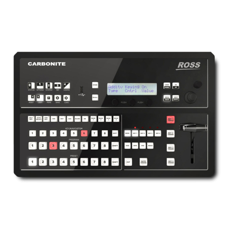
Ross Carbonite Black User guide

Carbonite Black
Setup Manual
v14.0

Thank You For Choosing
Ross
You've made a great choice. We expect you will be
very happy with your purchase of Ross Technology.
Our mission is to:
1. Provide a Superior Customer Experience
• offer the best product quality and support
2. Make Cool Practical Technology
• develop great products that customers love
Ross has become well known for the Ross Video Code
of Ethics. It guides our interactions and empowers our
employees. I hope you enjoy reading it below.
If anything at all with your Ross experience does not
live up to your expectations be sure to reach out to us
at solutions@rossvideo.com.
David Ross
CEO, Ross Video
dross@rossvideo.com
Ross Video Code of Ethics
Any company is the sum total of the people that make
things happen. At Ross, our employees are a special
group. Our employees truly care about doing a great
job and delivering a high quality customer experience
every day. This code of ethics hangs on the wall of all
Ross Video locations to guide our behavior:
1. We will always act in our customers' best interest.
2. We will do our best to understand our customers'
requirements.
3. We will not ship crap.
4. We will be great to work with.
5. We will do something extra for our customers, as
an apology, when something big goes wrong and
it's our fault.
6. We will keep our promises.
7. We will treat the competition with respect.
8. We will cooperate with and help other friendly
companies.
9. We will go above and beyond in times of crisis.
If there's no one to authorize the required action
in times of company or customer crisis - do what
you know in your heart is right. (You may rent
helicopters if necessary.)
ii • Thank You For Choosing Ross — Carbonite Black Setup Manual (v14.0)

Document Information
• Ross Part Number: 4804DR-120-14.0A
• Release Date: January, 2020. Printed in Canada
• Equipment: This document applies to the Carbonite
Black (4804AR-200-xx), Carbonite Black+
(4804AR-202-xx), and Carbonite Black+ 12G
(4804AR-204-xx) frames.
Copyright
©2020 Ross Video Limited, Ross®, MiniME™, and any
related marks are trademarks or registered trademarks
of Ross Video Limited. All other trademarks are the
property of their respective companies. PATENTS
ISSUED and PENDING. All rights reserved. No part
of this publication may be reproduced, stored in a
retrieval system, or transmitted in any form or by
any means, mechanical, photocopying, recording or
otherwise, without the prior written permission of Ross
Video. While every precaution has been taken in the
preparation of this document, Ross Video assumes no
responsibility for errors or omissions. Neither is any
liability assumed for damages resulting from the use of
the information contained herein.
Microsoft®, Windows®, and Windows XP® are either
registered trademarks or trademarks of Microsoft
Corporation in the United States and/or other countries.
Macintosh®, and OS X® are trademarks of Apple Inc.,
registered in the U.S. and other countries.
Google Chrome™, Google®, and the Google logo are
registered trademarks of Google Inc.
Patents
Patent numbers US 7,034,886; US 7,508,455; US
7,602,446; US 7,802,802 B2; US 7,834,886; US
7,914,332; US 8,307,284; US 8,407,374 B2; US
8,499,019 B2; US 8,519,949 B2; US 8,743,292 B2; US
D752,530 S; GB 2,419,119 B; GB 2,447,380 B; and
other patents pending.
Important Regulatory and Safety
Notices to Service Personnel
Before using this product and any associated
equipment, refer to the “ Important Safety
Instructions ” listed in the front of this manual to
avoid personnel injury and to prevent product damage.
Product may require specific equipment, and/or
installation procedures to be carried out to satisfy
certain regulatory compliance requirements. Notices
have been included in this publication to call attention
to these specific requirements.
Symbol Meanings
Protective Earth: This symbol identifies a
Protective Earth (PE) terminal, which is provided
for connection of the supply system's protective
earth (green or green/yellow) conductor.
Important: This symbol on the equipment refers
you to important operating and maintenance
(servicing) instructions within the Product Manual
Documentation. Failure to heed this information
may present a major risk of damage or injury to
persons or equipment.
Warning: The symbol with the word “ Warning ”
within the equipment manual indicates a potentially
hazardous situation which, if not avoided, could
result in death or serious injury.
CAUTION: The symbol with the word “ Caution ”
within the equipment manual indicates a potentially
hazardous situation which, if not avoided, may
result in minor or moderate injury. It may also be
used to alert against unsafe practices.
Warning Hazardous Voltages: This symbol
is intended to alert the user to the presence
of uninsulated “ dangerous voltage ” within
the product enclosure that may be of sufficient
magnitude to constitute a risk of shock to persons.
ESD Susceptibility: This symbol is used to alert
the user that an electrical or electronic device or
assembly is susceptible to damage from an ESD
event.
Important Safety Instructions
1. Warning: Read these instructions.
2. Keep these instructions.
3. Heed all warnings.
4. Follow all instructions.
5. Do not use this apparatus near water.
6. Clean only with a dry cloth.
7. Do not block any ventilation openings. Install in
accordance with manufacturer's instructions.
8. Do not install near heat sources such as radiators,
heat registers, stoves, or other apparatus (including
amplifiers) that produce heat.
9. Do not defeat the safety purpose of the polarized
or grounding-type plug. A polarized plug has two
blades with one wider than the other. A grounding
type plug has two blades and a third grounding
prong. The third prong is provided for your safety.
If the provided plug does not fit into your outlet,
Carbonite Black Setup Manual (v14.0) — Document Information • iii

consult an electrician for replacement of the
obsolete outlet.
10. Protect the power cord from being walked on
or pinched, particularly at plugs, convenience
receptacles, and the point where they exit from the
apparatus.
11. Only use attachments/accessories specified by the
manufacturer.
12. Unplug this apparatus during lightning storms or
when unused for long periods of time.
13. Refer all servicing to qualified service personnel.
Servicing is required when the apparatus has
been damaged in any way, such as when the
power-supply cord or plug is damaged, liquid
has been spilled or objects have fallen into the
apparatus, the apparatus has been exposed to rain
or moisture, does not operate normally, or has
been dropped.
14. Do not expose this apparatus to dripping or
splashing, and ensure that no objects filled with
liquids, such as vases, are placed on the apparatus.
15. To completely disconnect this apparatus from the
AC Mains, disconnect the power supply cord plug
from the AC receptacle.
16. The mains plug of the power supply cord shall
remain readily operable.
17. Warning: Indoor Use: To reduce the risk
of fire or electric shock, do not expose this
apparatus to rain or moisture.
18. The safe operation of this product requires that
a protective earth connection be provided. A
grounding conductor in the equipment's supply
cord provides this protective earth. To reduce
the risk of electrical shock to the operator and
service personnel, this ground conductor must be
connected to an earthed ground.
19. Warning: This apparatus, when equipped
with multiple power supplies, can generate
high leakage currents. To reduce the risk of
electric shock, ensure that each individual
supply cord is connected to its own separate
branch circuit with an earth connection.
20. CAUTION: These service instructions are
for use by qualified service personnel only.
To reduce the risk of electric shock, do
not perform any servicing other than that
contained in the operating instructions unless
you are qualified to do so.
21. Service barriers within this product are intended
to protect the operator and service personnel from
hazardous voltages. For continued safety, replace
all barriers after servicing.
22. Certain parts of this equipment still present a
safety hazard with the power switch in the OFF
position. To avoid electrical shock, disconnect all
A/C power cords from the chassis' rear appliance
connectors before servicing.
23. This product contains safety critical parts, which,
if incorrectly replaced, may present a risk of fire
or electrical shock. Components contained within
the product's power supplies and power supply
area are not intended to be customer-serviced and
should be returned to the factory for repair.
24. To reduce the risk of fire, replacement fuses must
be the same type and rating.
25. Use only power cords specified for this product
and certified for the country of use.
26. The safe operation of this equipment requires
that the user heed and adhere to all installation
and servicing instruction contained within the
equipment's Setup Manuals.
27. Warning: This product includes an “
Ethernet Port ” which allows this product to
be connected to a local area network (LAN).
Only connect to networks that remain inside
the building. Do not connect to networks that
go outside the building.
28. CAUTION: This apparatus contains a
Lithium battery, which if replaced incorrectly,
or with an incorrect type, may cause an
explosion. Replace only with a CR2032 coin
type lithium battery. Dispose of used batteries
according to the manufacturer's instruction by
qualified service personnel.
EMC Notices
United States of America — FCC Part 15
This equipment has been tested and found to comply
with the limits for a class A Digital device, pursuant
to part 15 of the FCC Rules. These limits are designed
to provide reasonable protection against harmful
interference when the equipment is operated in a
commercial environment. This equipment generates,
uses, and can radiate radio frequency energy and, if not
installed and used in accordance with the instruction
manual, may cause harmful interference to radio
communications. Operation of this equipment in a
residential area is likely to cause harmful interference
in which case the user will be required to correct the
interference at his own expense.
Important: Changes or modifications to this
equipment not expressly approved by Ross Video
Limited could void the user's authority to operate
this equipment.
iv • Document Information — Carbonite Black Setup Manual (v14.0)

Canada
This Class “ A ” digital apparatus complies with
Canadian ICES-003.
Cet appareil numérique de la classe “ A ” est
conforme a la norme NMB-003 du Canada.
Europe
This equipment is in compliance with the essential
requirements and other relevant provisions of CE
Directive 93/68/EEC.
International
This equipment has been tested to CISPR 22:1997
along with amendments A1:2000 and A2:2002, and
found to comply with the limits for a Class A Digital
device.
Important: This is a Class A product. In domestic
environments, this product may cause radio
interference, in which case the user may have to
take adequate measures.
General Handling Guidelines
• Careful handling, using proper ESD precautions,
must be observed.
• Power down the system before PCB removal.
A Word About Static Discharge
Throughout the many procedures in this manual, please
observe all static discharge precautions.
CAUTION: Avoid handling the switcher circuit
boards in high static environments such as
carpeted areas, and when synthetic fiber clothing
is worn. Touch the frame to dissipate static
charge before removing boards from the frame,
and exercise proper grounding precautions
when working on circuit boards. Exercise proper
grounding precautions when working on circuit
boards.
Warranty and Repair Policy
Ross Video Limited (Ross) warrants its switchers
and related options, to be free from defects under
normal use and service for a period of ONE YEAR
from the date of shipment. Fader handle assemblies
are warranted for the life of the product. If an item
becomes defective within the warranty period Ross
will repair or replace the defective item, as determined
solely by Ross.
Warranty repairs will be conducted at Ross, with all
shipping FOB Ross dock. If repairs are conducted
at the customer site, reasonable out-of-pocket
charges will apply. At the discretion of Ross, and
on a temporary loan basis, plug in circuit boards
or other replacement parts may be supplied free of
charge while defective items undergo repair. Return
packing, shipping, and special handling costs are the
responsibility of the customer.
Software upgrades for switchers may occur from
time to time, and are determined by Ross Video. The
upgrades are posted on the Ross Video website, and are
free of charge for the life of the switcher.
This warranty is void if products are subjected to
misuse, neglect, accident, improper installation or
application, or unauthorized modification.
In no event shall Ross Video Limited be liable for
direct, indirect, special, incidental, or consequential
damages (including loss of profit). Implied warranties,
including that of merchantability and fitness for a
particular purpose, are expressly limited to the duration
of this warranty.
This warranty is TRANSFERABLE to subsequent
owners, subject to Ross Video's notification of change
of ownership.
Environmental Information
Waste Electrical and Electronic Equipment
Directive (WEEE Directive)
The equipment that you purchased required the
extraction and use of natural resources for its
production. It may contain hazardous substances
that could impact health and the environment.
To avoid the potential release of those substances
into the environment and to diminish the need for the
extraction of natural resources, Ross Video encourages
you to use the appropriate take-back systems. These
systems will reuse or recycle most of the materials
from your end-of-life equipment in an environmentally
friendly and health conscious manner.
The crossed-out wheeled bin symbol invites you to use
these systems.
If you need more information on the collection, reuse,
and recycling systems, please contact your local or
regional waste administration.
You can also contact Ross Video for more information
on the environmental performances of our products.
Carbonite Black Setup Manual (v14.0) — Document Information • v

Use of Hazardous Substances in Electrical
and Electronic Products (China RoHS)
Ross Video Limited has reviewed all components and
processes for compliance to:
“ Management Methods for the Restriction of the Use
of Hazardous Substances in Electrical and Electronic
Products ” also known as China RoHS.
The “ Environmentally Friendly Use Period ” (EFUP)
and Hazardous Substance Tables have been established
for all products. We are currently updating all of our
Product Manuals.
The Hazardous substances tables are available on
our website at: http://www.rossvideo.com/about-ross/
company-profile/green-practices/china-rohs.html
电器电子产品中有害物质的使用
Ross Video Limited 按照以下的标准对所有组件和
流程进行了审查:
“ 电器电子产品有害物质限制使用管理办法 ” 也被
称为中国RoHS。
所有产品都具有 “ 环保使用期限 ” (EFUP)和有
害物质表。目前,我们正在 更新我们所有的产品
手册。
有害物质表在我们的网站:http://
www.rossvideo.com/about-ross/company-profile/green-
practices/china-rohs.html
Company Address
Ross Video Limited — 8 John Street Iroquois,
Ontario, Canada, K0E 1K0
Ross Video Incorporated — P.O. Box 880,
Ogdensburg, New York, USA, 13669-0880
General Business Office: (+1)613-652-4886
Fax: (+1)613-652-4425
Toll Free Technical
Support (North America):
1-844-652-0645
Toll Free Technical
Support (International):
+800 1005 0100
Technical Support: (+1)613-652-4886
After Hours Emergency: (+1)613-349-0006
E-Mail (Support): techsupport@rossvideo.com
E-Mail (General): solutions@rossvideo.com
Website www.rossvideo.com
Technical Support
At Ross Video, we take pride in the quality of our
products, but if a problem does occur, help is as close
as the nearest telephone.
Our 24-Hour Hot Line service ensures you have access
to technical expertise around the clock. After-sales
service and technical support are provided directly
by Ross Video personnel. During business hours
(eastern standard time), technical support personnel
are available by telephone. Outside of normal business
hours and on weekends, a direct emergency technical
support phone line is available. If the technical support
personnel who is on call does not answer this line
immediately, a voice message can be left and the call
will be returned shortly. Our Technical support staff are
available to react to any problem and to do whatever is
necessary to ensure customer satisfaction.
Supporting Documentation
Ross Video provides a wide variety of helpful
documentation for the setup and support of your
equipment. Most of this documentation can be
found either on the Product Resources disk that
came with your equipment, on the Ross Video
website (www.rossvideo.com), or on the Ross Video
Community site (discussions.rossvideo.com/)
•Carbonite Online Help for DashBoard — visit
help.rossvideo.com/carbonite
•Operation Manual (4804DR-110) — operational
instructions for all Carbonite Black switchers
•Setup Manual (4804DR-120) — setup and
configuration instructions for Carbonite Black and
Carbonite Black+ frames
•Carbonite Black QuickStart Poster
(4804DR-200) — setup information and
specifications for the Carbonite Black and
Carbonite Black+ frames
•Upgrade Notes (4802DR-500) — upgrade
instructions, new features, and known issues for a
given software version
•Software Licenses (4802DR-502) — third-party
software licences
•Carbonite Multilingual Safety Information
(4802DR-503) — translated product safety
information
•Carbonite Frame Fan Replacement
(4802DR-300) — instructions for replacing cooling
fans in the Carbonite, Carbonite+, Carbonite
MultiMedia, Carbonite Black, or Carbonite Black+
frames
•Carbonite Frame RAM Replacement
(4802DR-301) — instructions for replacing the
vi • Document Information — Carbonite Black Setup Manual (v14.0)

RAM in the Carbonite, Carbonite+, or Carbonite
MultiMedia frames
•Control Panel Desk Mounting (4802DR-302) —
desk mounting instructions for Carbonite control
panel
•SideBox Installation (4802DR-304) — installation
and mounting instruction for SideBox module
•Auxiliary Control Panel Installation
(4802DR-305) — installation and mounting
instruction for remote aux panel (CPS-AUX-053B)
•GVG100 Supported Command (4802DR-401) —
connection and GVG100 commands supported by
the switcher
•RossTalk Commands (4802DR-403) — supported
commands using RossTalk protocol
•Device Setup Sheets (4802DR-6xx) — setup
information for controlling external devices from
the switcher
•Robotic Camera Control (4802DR-131) —
overview of the operational interface when
controlling a robotic camera from the switcher
•Audio Mixer Control (4802DR-132) — overview
of the operational interface when controlling an
audio mixer from the switcher
•Video Server Control (4802DR-133) — overview
of the operational interface when controlling a
video server from the switcher
•Configuration Guide (4804DR-100) — product
description and marketing codes for switchers and
options
•CarboNET Installation (4805DR-100) —
installation instructions for the Carbonite PMC
translator.
•Carbonite Operation Manual (4802DR-110) —
operational instructions for all Carbonite switchers
•Carbonite Black Operation Manual
(4804DR-110) — operational instructions for all
Carbonite Black switchers
•Carbonite Setup Manual (4802DR-120) —
setup and configuration instructions for Carbonite,
Carbonite+, and Carbonite MultiMedia frames
•Carbonite eXtreme Setup Manual (4803DR-120)
— setup and configuration instructions for
Carbonite eXtreme frames
•Carbonite Black Setup Manual (4804DR-120) —
setup and configuration instructions for Carbonite
Black frame
•Carbonite QuickStart Poster (4802DR-200)
— setup information and specifications for the
Carbonite, Carbonite+, and Carbonite MultiMedia
frames
•Carbonite eXtreme QuickStart Poster
(4803DR-200) — setup information and
specifications for the Carbonite eXtreme frame
•Carbonite Black QuickStart Poster
(4804DR-200) — setup information and
specifications for the Carbonite Black frames
•Carbonite Upgrade Notes (4802DR-500) —
upgrade instructions, new features, and known
issues for a given software version.
•Carbonite Black Upgrade Notes (4804DR-500)
— upgrade instructions, new features, and known
issues for a given software version.
•Carbonite eXtreme Upgrade for NK-3G144-X
— upgrade instructions for the NK-3G144-X router
to a Carbonite eXtreme switcher
•Software Licenses (4802DR-502) — third-party
software licences
•Carbonite Multilingual Safety Information
(4802DR-503) — translated product safety
information
•Carbonite Frame Fan Replacement
(4802DR-300) — instructions for replacing cooling
fans in the Carbonite, Carbonite+, Carbonite
MultiMedia, or Carbonite Black frames
•Carbonite Frame RAM Replacement
(4802DR-301) — instructions for replacing the
RAM in the Carbonite, Carbonite+, or Carbonite
MultiMedia frames
•Control Panel Desk Mounting (4802DR-302) —
desk mounting instructions for Carbonite control
panel
•SideBox Installation (4802DR-304) — installation
and mounting instruction for SideBox module
•Auxiliary Control Panel Installation
(4802DR-305) — installation and mounting
instruction for remote aux panel (CPS-AUX-053B)
•GVG100 Supported Command (4802DR-401) —
connection and GVG100 commands supported by
the switcher
•RossTalk Commands (4802DR-403) — supported
commands using RossTalk protocol
•Device Setup Sheets (4802DR-6xx) — setup
information for controlling external devices from
the switcher
•Robotic Camera Control (4802DR-131) —
overview of the operational interface when
controlling a robotic camera from the switcher
•Audio Mixer Control (4802DR-132) — overview
of the operational interface when controlling an
audio mixer from the switcher
•Video Server Control (4802DR-133) — overview
of the operational interface when controlling a
video server from the switcher
Carbonite Black Setup Manual (v14.0) — Document Information • vii

•Carbonite Configuration Guide (4802DR-100)
— product description and marketing codes for
switchers and options
•Carbonite Black Configuration Guide
(4804DR-100) — product description and
marketing codes for switchers and options
•CarboNET Installation (4805DR-100) —
installation instructions for the Carbonite PMC
translator.
viii • Document Information — Carbonite Black Setup Manual (v14.0)

Contents
Features.............................................................11
Analog Reference Input and Output.....................................11
UHDTV1 Video Formats....................................................... 11
Integrated Up/Down Converters........................................... 11
Custom Controls................................................................... 11
Device Control...................................................................... 11
DVE (Fly Key).......................................................................11
Effects Dissolve.................................................................... 11
General Purpose Interface (GPI)..........................................11
LiveEDL.................................................................................11
Media-Store...........................................................................11
MediaWipe............................................................................ 12
UltraChrome 2.......................................................................12
MemoryAI Recall Mode........................................................ 12
Memory System....................................................................12
ME Effect System................................................................. 12
MiniME™................................................................................ 12
DashBoard Integration.......................................................... 12
MultiViewer............................................................................ 12
Clean Feed Output............................................................... 13
Pattern and Matte/Wash Generators.................................... 13
Matte/Wash Generator..........................................................13
Tally Outputs......................................................................... 13
Network Connections...................................... 14
Frame Network Setup (Ethernet)........................................ 14
Connecting to the Switcher from DashBoard.........14
To Change the IP Address....................................14
Frame Network Setup (Serial).............................................14
To Set an IP Address Using DHCP....................... 14
To Set a Static IP Address.................................... 15
Panel Network Setup............................................................15
To Configure the Network Setting......................... 15
To Assign a Custom Name................................... 15
FTP Connection (RossLinq)................................................. 16
To Create an FTP Connection with Windows 7..... 16
Video Reference............................................... 17
Supported Reference Formats............................................. 17
Reference and Video Mode Setup....................................... 17
To Set a Video Mode............................................ 17
Frame Sync and Format Conversion....................................17
Supported FSFC Video Formats.......................... 18
To Set Up Input FSFC...........................................18
To Set Up Output FSFC........................................18
Output Reference Synchronizers..........................................18
To Set Up an Output Reference Sync................... 18
To Set Color Framing for Analog Reference..........19
Video Input Setup............................................ 20
Input Format Type................................................................ 20
To Configure The Input Format Type.................... 20
Auto Key Setup.....................................................................20
To Set Up an Auto Key Association...................... 20
Source Names...................................................................... 21
To Set Up a Source Name.................................... 21
To Assign a TSL ID to a Video Input..................... 21
Control Panel Button Inserts.................................................22
To Install a Button Insert....................................... 22
Bus Maps.............................................................................. 22
To Create a Bus Map............................................ 23
To Reset the Bus Map.......................................... 23
GPI Device Control...............................................................23
To Assign a GPI to a Video Source.......................23
Video Outputs...................................................24
Output Sources.....................................................................24
To Assign a Source to an Output.......................... 24
Ancillary Data........................................................................24
To Strip or Pass Ancillary Data............................. 24
FlexiClean Clean Feed......................................................... 25
To Set Up Clean Feed.......................................... 25
External Layer Mode............................................................ 25
To Set Up Layer Mode.......................................... 25
MultiViewer............................................................................ 25
Carbonite Black+/Carbonite Black+ 12G
MultiViewer Sources.......................................25
To Set Up a MultiViewer....................................... 26
To Set Up a MultiViewer Clock..............................27
On-Air Setting....................................................................... 27
To Set the On-Air Status for an Output................. 27
Tallies.................................................................................... 28
To Set Up a Tally.................................................. 28
Media-Store Audio Output...............................29
To Assign Media-Store Audio to an AES Output.................. 29
Color Correction...............................................30
Proc Amp Color Correction.................................................. 30
To Apply a Proc Amp to a Video Source............... 30
To Apply a Proc Amp to a Video Output................30
RGB Color Correction...........................................................31
To Apply a RGB Color Correction to a Video
Source............................................................ 31
To Apply a RGB Color Corrector to a Video
Output............................................................. 32
ViewControl.......................................................33
Connecting ViewControl........................................................33
To Set Up The Video Input for ViewControl........... 33
To Set Up the MultiViewer for ViewControl............33
Switcher Personality........................................ 34
Auto Remove Key.................................................................34
To Set the Auto Remove Key Behavior................. 34
Auto Trans Second Press.....................................................34
To Set the Auto Trans Second Press Behavior......34
Background Double-Press.................................................... 34
To Set the Background Double-Press
Behavior..........................................................34
Color Schemes..................................................................... 34
To Select a Panel Color Scheme.......................... 34
To Create a Custom Panel Color Scheme.............35
To Set the Brightness of the Control Panel
Buttons............................................................35
Double-Press Rate................................................................35
To Set the Double-Press Rate.............................. 35
Editor Mode...........................................................................35
To Set the Switcher to Editor Mode.......................35
Memory Bank Button Behavior.............................................35
To Set the Bank Button Behavior.......................... 35
Next Button Secondary Function..........................................35
To Set the NEXT Button Secondary Function........35
Next Transition Reset........................................................... 36
To Set the Next Transition Reset Behavior............36
Next Transition Toggle.......................................................... 36
To Set the Next Trans Toggle................................36
Power-Save Mode................................................................ 36
To Set the Power Save Mode and Timer...............36
Roll GPO/Roll Clip................................................................ 36
To Set the Roll GPO/Clip Behavior....................... 36
Shift Toggle........................................................................... 36
To Set the Shift Toggle..........................................37
Carbonite Black Setup Manual (v14.0) — Contents • ix
Transition Rate Units............................................................ 37
To Set the Units Used for Transition Rates........... 37
Undo Memory Recall............................................................ 37
To Turn Undo Memory Recall Off..........................37
User Buttons......................................................................... 37
To Set A User Button............................................ 37
Switcher Resources.........................................38
GPI Control....................................................... 39
GPI Trigger Types.................................................................39
GPI Setup............................................................................. 39
To Set Up a GPI Input.......................................... 39
To Set Up a GPI Output........................................40
GPI Output Triggers..............................................................40
To Assign a GPI Output to a Video Source........... 41
To Set a GPI to Be Triggered Manually.................41
Live Edit Decision Lists.................................. 42
LiveEDL Setup......................................................................42
To Set the LiveEDL Behavior................................ 42
Timecode Setup....................................................................42
To Confirm External LTC Signal............................ 42
To Set the LTC Timecode Source......................... 42
LiveEDL Data Capture..........................................................43
To Start Capturing EDL Data................................ 43
To Stop Capturing and Save EDL Data.................43
MultiPanel..........................................................44
To Set Up MultiPanel Permissions....................................... 44
Diagnostics and Calibration............................45
Switcher Information and Logs............................................. 45
Switcher Status in DashBoard............................. 45
To View the Software Version............................... 45
To Copy Logs To a USB....................................... 45
Calibration............................................................................. 45
To Calibrate the Switcher...................................... 45
System Real-Time Clock/Date..............................................46
To Set the System Real-Time Clock......................46
To Set the System Date........................................ 46
Diagnostics............................................................................46
Frame Diagnostic LEDs........................................ 46
Frame DIP Switches............................................. 46
Control Panel DIP Switches.................................46
To Run the Control Panel Test.............................. 47
To Run the LED Test.............................................47
To Run the Display Test........................................ 47
To Run the Tally Test............................................ 47
To Run the GPI Input Test.................................... 47
To Run the GPI Output Test..................................47
Error Messages.....................................................................47
Specifications................................................... 48
Switcher Resources.............................................................. 48
Hardware Weights................................................................ 48
Environmental Characteristics.............................................. 48
Video Input Specifications.................................................... 48
Video Output Specifications..................................................48
Audio Specifications..............................................................49
Jitter.......................................................................................49
System Timing...................................................................... 49
Power Consumption — Control Panel..................................49
Power Consumption — Frame............................................. 49
Ports.................................................................. 50
Serial Port............................................................................. 50
GPI Port................................................................................ 50
Tally Port............................................................................... 50
LTC Port................................................................................51
AES Port............................................................................... 51
Glossary...............................................52
Index.....................................................55
x • Contents — Carbonite Black Setup Manual (v14.0)

Features
Thank you for buying a Ross Video Carbonite Black
Series Multi-Definition Live Production Switcher.
The Carbonite Black series builds on the Ross Video
reputation for designing switchers that fit the needs of
any production environment.
Analog Reference Input and Output
The switcher supports both external and internal
reference sources. The external reference can be an
input from a house sync to the single reference input
BNC. The internal reference can also be used as a
house sync with selectable tri-level sync or analog
black burst with independent H/V settings for each of
the two reference output BNCs.
Although tri-level sync is recommended as your
reference source for all HD applications, analog black
burst can be used when operating the switcher.
UHDTV1 Video Formats
The switcher supports UHDTV1 3840×2160 59.94Hz
and 50Hz in quad link UHD-2SI (3Gb/s and 12Gb/s)
and UHD-QSD video formats.
Integrated Up/Down Converters
All switchers come with integrated up/down converters
and frame synchronizers (FSFC) capable of converting
1080p, 1080i, 720p, and UHD-QSD to UHD-2SI and
back again on output, at the same frequency.
Custom Controls
This feature brings the power of macros to the switcher
operator. Button presses, menu selections, event
commands, or even the switcher state can be recorded
to a custom control with pauses or holds between the
events. A simple button press can play these events
back again. Step through complex show openings as
easily as pressing Custom Control buttons 1, 2, then 3.
Device Control
The switcher can control a number of external
devices, such as video servers and robotic cameras. For
a complete list of supported devices, and information
on how to set up and control these devices, visit the
Ross Video website (help.rossvideo.com/carbonite-
device).
DVE (Fly Key)
The advanced 2D DVE comes standard with each
switcher, and can be used for performing over the
shoulder, or picture in picture shots. This allows all
key types to be zoomed, cropped, and repositioned
horizontally and vertically to create the look you want,
or you can use one of the useful pre-built 2D effects to
perform 2D background transitions.
Effects Dissolve
The Effects Dissolve feature allows you to interpolate
from one memory to another using a memory recall.
The switcher will interpolate from the starting memory
to the destination memory, creating a smooth, two key
frame effect.
Only elements such as clip level and pattern position
can be interpolated in the effects dissolve. Other
elements, such as crosspoint selection and next
transition data are recalled first, and then the switcher
will slew to the recalled memory.
An effects dissolve can be performed on as many
elements and MEs as required, based on the memory
that is being recalled.
General Purpose Interface (GPI)
The switcher is equipped with 34 GPI I/Os that can be
assigned as either an input or output independently.
The GPI inputs allow the switcher to interface with
peripheral equipment such as editors. Each GPI input
can be used to perform simple editing and switcher
functions such as fade to black or an auto transition.
LiveEDL
Edit Decision Lists (EDL) are files used by non-linear
editing (NLE) suites to aid in post-production. Your
switcher can capture EDL data in a file that you load
into your NLE suite.
Media-Store
Up to 2 independent channels of still/animations are
available switcher-wide, allowing for thousands of full
screen stills and logos that can be cached and used on
the switcher.
Carbonite Black Setup Manual (v14.0) — Features • 11

Media-Store provides 8 GB of cache. The number of
images cached increases considerably when smaller,
non-full screen images like logos are loaded from
USB.
MediaWipe
A MediaWipe allows you to use an animation
from the Media-Store to play over a background
or key transition. When the transition starts, the
switcher plays the selected animation over top of the
background and keys that are being transitioned. A cut,
dissolve, wipe, or DVE wipe is then performed layered
under the animation to bring up the next shot when the
animation ends.
UltraChrome 2
The UltraChrome 2 chroma keyers uses advanced
video processing technology to provide exceptional
blue spill reduction and clean edges, even with difficult
source material. Glass, smoke, translucent materials,
and natural shadows are handled superbly.
The 2 UltraChrome 2 chroma key engines can be
selected on any bus as a source or have the generated
video and alpha output to a downstream device, such
as a video server.
MemoryAI Recall Mode
We take the guessing out of memory recalls by
ensuring that a memory recall will not affect what is
currently on-air. MemoryAI uses the content of the
memory to configure the Next Transition area and
Preview bus for the background and keyers so that the
next transition takes the same sources on-air that were
on-air in the memory.
For example, store a memory that has a key on-air with
CAM1 and CAM2 selected on the background. When
this memory is recalled normally, it pops the same
key on-air with CAM1 and CAM2 on the background.
When the memory is recalled with MemoryAI turned
on, CAM1 is selected on the preset bus, and CAM2
is selected on a key that is not on-air. The transition
area is then set up for a background transition to bring
CAM2 onto the background, take any on-air keys off,
and take a key on-air with CAM1.
Memory System
Storage for 100 complete switcher snapshots per ME,
MiniME™, and chroma key comes standard with all
switchers. All of these memories can be stored to a
USB media drive, providing custom tailored memories
for every operator and every show.
ME Effect System
The ME (Multi-level Effect) systems are standard. The
number of MEs depends on the chosen switcher model.
MiniME™
The MiniME™ is an additional ME that is provided
with the switcher to perform basic dissolves and cuts.
Each MiniME™ has 2 keyers, background, and preset
buses. Unlike a full ME, the MiniME™ only supports
dissolves and cuts. The MiniME™ shares all the same
sources as the ME.
DashBoard Integration
Carbonite it fully integrated with DashBoard allowing
you to set up and control your switcher from any
computer running DashBoard and an ethernet
connection to the switcher frame.
MultiViewer
Each MultiViewer allows you to view up to 16 video
sources, in 45 different layouts, from a single output
BNC. Any video source on the switcher, including ME
Program, Preview, and Media-Store channels, can be
routed to any box on the MultiViewer. All boxes on the
MultiViewer output include mnemonic source names
and red and green tallies.
The Carbonite Black comes standard with 1 broadcast-
quality integrated MultiViewer generator and the
Carbonite Black+/Carbonite Black+ 12G come
standard with 4. The additional MultiViewer outputs
on the Carbonite Black+/Carbonite Black+ 12G are
only available on dedicated output BNCs and only
support 10 boxes. Each of these MultiViewer outputs
has a specific range of input and output BNCs that can
be assigned to boxes on the MultiViewer.
12 • Features — Carbonite Black Setup Manual (v14.0)

Figure 1: HD Layouts
Figure 2: MultiViewer Grid
Note: The MultiViewer is output in 1080p 50 or 59.94Hz only.
Clean Feed Output
Clean feed is typically used for bilingual and live-
to-tape productions. It provides a second Program
output that is derived from a different location than
the standard program output. A frequent application is
the recording of shows for later airing without call-in
phone numbers inserted.
The clean feed output can come from before or
between the keyers.
Pattern and Matte/Wash Generators
A single pattern generator dedicated to wipes comes
standard, and is equipped with 10 classic wipes. Most
wipes can be rotated, bordered, multiplied, aspectized,
and repositioned.
Matte/Wash Generator
A matte generator and complex wash generator per
ME, capable of multi-color washes comes standard.
Any one of the color generators can be assigned to
MATTE. An additional simple color generator is
available for an Aux Bus.
Tally Outputs
The switcher has 34 assignable tally relays located
in the rack frame. Each tally can be assigned to any
number of combinations of input and output or bus.
Carbonite Black Setup Manual (v14.0) — Features • 13

Network Connections
The control panel connects to the frame in one of three
ways, depending on the model of control panel or
option you have.
•Carbonite Black — panel connects to the frame
over a standard ethernet connection
•CarboNET — panel connects to the CarboNET
over a serial connection and the CarboNET
connects to the frame over a standard ethernet
connection
•Carbonite — panel connects to the frame over a
serial connection (Panel to Frame port)
The ethernet connection from the frame is also used to
upload stills to the Media-Store channels, download
switcher data files, or control switcher functions using
DashBoard.
The switcher uses the following network ports:
•FTP — 21
•SSH — 21
•DashBoard — 5253
•SLP — 427
•Web Server — 80
•RossTalk — 7788
Frame Network Setup (Ethernet)
If you are connecting to the frame over ethernet you
must use DashBoard to set the IP address of the frame.
The frame comes from the factory set with a static IP
address (192.168.0.123) but can be set to use DHCP to
automatically obtain an IP address.
Note: If you use a DHCP server, it must be set to always give
the frame the same IP address. DashBoard, the Carbonite
Black control panel, and CarboNET need a fixed IP address to
connect to.
Tip: If you do not know the IP address of the frame, you
can set DIP switch 3 on the frame to lock the IP address to
192.168.0.123. The frame must be re-started for the new IP
address to be applied.
Connecting to the Switcher from DashBoard
DashBoard should automatically detect and connect
to the frame once it is connected to the same subnet.
If you have trouble discovering the switcher frame,
or it is located on another subnet, you can manually
connect DashBoard to the switcher to establish
communications. Once connected, DashBoard will
remember the connection until you remove it.
To Manually Connect to the Frame To
Connect to the Frame
You need the IP address of the frame to connect to it
manually from DashBoard.
1. Click File > New > Manual Connection.
2. In the IP Address field, enter the IP address
of the switcher frame. The default IP address is
192.168.0.123.
Tip: If the control panel is connected to the frame over
a serial link, the IP address can be found through the
menu system (Press MENU > System > NEXT > NEXT >
FrmIP Addr).
3. Click Detect Settings.
4. Click Finish.
The frame appears in the Tree View.
To Change the IP Address
1. Click Navigation Menu > Configuration >
Network.
2. Enter a name in the Switcher Name field.
This is the name that appears in the tree view in
DashBoard.
3. Click Edit.
4. Click an ETHX Mode button to set that network
port to use DHCP (DHCP), or a static IP address
(Static).
5. For a static IP address, enter the IP address
(ETHX IP Address), subnet mask (ETHX
Subnet Mask), and gateway (Gateway) you
want to use.
6. Click Update.
Frame Network Setup (Serial)
If you are connecting to the frame over a serial
connection (Carbonite) you can use the control panel to
initially configure the network settings for the frame.
To Set an IP Address Using DHCP
Due to the nature of DHCP, your switcher may get a
different IP address each time it is powered on or re-
connected to a network. You must have the switcher
connected to a network to be able to obtain an IP
address using DHCP.
Note: Ensure that DIP switch 3 on the frame is set in the up
position. If this DIP switch is set in the down position, the IP
address is fixed at 192.168.0.123. Ensure that DIP switch 3
on the frame is set in the up position. If this DIP switch is set in
the down position, the IP address is fixed at 192.168.0.123.
1. Press MENU > System > NEXT > NEXT >
FrmIP Addr.
14 • Network Connections — Carbonite Black Setup Manual (v14.0)

2. Use the left knob to select the network port that
you want to set to DHCP. Only one port can be set
to DHCP at a time.
•1-Mode — network port 1
•2-Mode — network port 2
3. Press the Edit knob.
4. Use the Value knob to select DHCP.
5. Press the Value knob.
6. Press the Reboot knob to restart the switcher in
DHCP mode.
The switcher will request an IP address when it
restarts.
To Set a Static IP Address
You must have the switcher connected to a network
to be able to set a static IP. If the switcher is not
connected to a network, the switcher does not display
the IP address.
Note: Ensure that DIP switch 3 on the frame is set in the up
position. If this DIP switch is set in the down position, the IP
address is fixed at 192.168.0.123. Ensure that DIP switch 3
on the frame is set in the up position. If this DIP switch is set in
the down position, the IP address is fixed at 192.168.0.123.
1. Press MENU > System > NEXT > NEXT >
FrmIP Addr.
2. Use the left knob to select the network port that
you want to set a static IP address for.
•1-Mode — network port 1
•2-Mode — network port 2
3. Press the Edit knob.
4. Use the Value knob to select Static.
5. Press NEXT.
6. Use the left knob to select 1-Addr for port 1 or 2-
Addr for port 2.
a) Use the Field knob to select the segment in
the address that you want to change.
b) Use the Value knob to select the new value
you want to use for that segment.
7. Use the left knob to select 1-Mask for port 1 or 2-
Mask for port 2.
a) Use the Field knob to select the segment in
the mask that you want to change.
b) Use the Value knob to select the new value
you want to use for that segment.
8. Use the left knob to select Gatwy.
a) Use the Field knob to select the segment in
the gateway that you want to change.
b) Use the Value knob to select the new value
you want to use for that segment.
9. Press the Gatwy knob.
10. Press the Reboot knob to restart the switcher in
with the new static IP address.
Panel Network Setup
The Carbonite Black control panel comes from the
factory set with a static IP address (192.168.0.129) but
can be set to use DHCP to automatically obtain an IP
address.
The control panel is automatically discovered in
DashBoard and appears as CarbonitePanel followed
by the MAC address of that particular panel.
Tip: If you do not know the IP address of the control panel,
you can set DIP switches on the panel to lock the IP address
of the panel to 192.168.0.129 and the IP address that it
expects the frame at to 192.168.0.123. The panel must be re-
started for the new IP address to be applied. Refer to Control
Panel DIP Switches on page 46 for DIP settings.
To Configure the Network Setting
1. Double-click on the CarbonitePanel node and
click on the Ethernet tab.
Note: The Current DIP Switch field shows the state of
the DIP1 and DIP2 switches on the control panel. Some
settings do not allow you to change the IP settings from
DashBoard.
2. Click a Method button to select whether to use a
static IP address (Static), or obtain an IP address
(DHCP).
3. For a static IP address, enter the IP address (IP
Address), subnet mask (Subnet Mask), and
gateway (Default Gateway) you want to use.
4. In the Carbonite IP Address field, enter the IP
address of the frame you are connecting to.
5. Click a Panel ID button to select whether you
want to assign the panel as the master panel
(Master), or one of the satellite panels (Sat. 1 or
Sat. 2). The panel id sets what permissions the
control panel has to the resources on the frame.
6. Click Apply Changes.
To Assign a Custom Name
The name appears in the tree view in DashBoard and
allows you to easily identify your particular device.
Carbonite Black Setup Manual (v14.0) — Network Connections • 15

1. Double-click on the CarbonitePanel node and
click on the Panel Name, Permissions tab.
2. In the Panel Name field, enter the new name.
FTP Connection (RossLinq)
You can create a File Transfer Protocol (FTP)
connection from a computer to your switcher. You
can use the FTP connection to copy still images and
animations to and from your switcher as well as copy
Edit Decision List (EDL) files from your switcher.
The procedure for creating an FTP connection from a
computer varies between operating systems and client
software. Consult with the documentation that came
with your computer for assistance with creating an FTP
connection.
To Create an FTP Connection with Windows 7
This procedure applies to Microsoft® Windows XP®
Professional and Windows® 7.
1. On your computer launch Windows Explorer.
2. In the address bar, type ftp://IP Address of
your switcher.
You are prompted for a username and password.
3. Type the user name for the application your are
creating an FTP connection for. Each application
has specific requirements. The switcher will set
these requirements automatically based on the
username.
•xpression – used when creating a
connection from a Ross® XPression Motion
Graphics System directly to the Media-Store
channels on the switcher, as well as any USB
drive installed in the switcher
•liveedl – used to create a connection to the
LiveEDL folder on the switcher to download
an edit decision list file form the switcher
•user – used to create a connection to the
general storage folders on the switcher, as well
as any USB drive installed in the switcher
4. Enter the password password
16 • Network Connections — Carbonite Black Setup Manual (v14.0)

Video Reference
The flexible reference system in the switcher allows
you to use an Interlaced video format as the reference
to operate the switcher in a video format of the same
frequency. Choosing a progressive video format as a
reference limits you to operating the switcher only in
that same video format and frequency.
Supported Reference Formats
The switcher supports a number of reference modes for
both internal and external reference signals.
Table 1: Supported Reference Formats
Input Reference Usable Format
720p 59.94Hz UHDTV1 59.94Hz (UHD-2SI)
720p 50Hz UHDTV1 50Hz (UHD-2SI)
1080i 59.94Hz UHDTV1 59.94Hz (UHD-2SI)
1080i 50Hz UHDTV1 50Hz (UHD-2SI)
Reference and Video Mode Setup
The switcher supports both internal and external
references. An external reference is provided by an
external device to the switcher through the REF IN
BNC on the frame. An internal reference is generated
by the switcher and can be fed out to other devices.
The switcher automatically detects the reference signal
and only shows the video modes that you can operate
the switcher in that are supported for that reference
format.
To Set a Video Mode
If you are using an external reference, ensure that a
proper reference is connected to the REF IN input
BNC on the frame.
Note: You must use an interlaced reference source to have
the switcher operate in an interlaced reference format if you
are using an external reference.
Tip: Reference settings can also be set up from the
Reference tab on the Configuration node in DashBoard.
1. Press MENU > Ref Click Navigation Menu >
Configuration > Reference.
2. Use the VidMode knob to select the video format
that you want to use. Click the Video Mode
button and select the video format you want to
use.
The available video modes depends on the
reference format coming into the switcher.
3. Press NEXT.
4. Use the RefSrc knob to select an internal (Int)
or external (Ext) reference source. Click the
Reference Source button and select an internal
or external reference source.
5. Press the RefSrc knob to confirm the reference
source.
Frame Sync and Format
Conversion
The switcher has multiple input frame synchronizer /
format converter (FSFC) and input de-interlacers
that can be used to convert video input signals to the
format that the switcher is operating in, as well as
correct mistimed, or drifting, video input signal. The
frame synchronizers cannot completely correct badly
formatted video, mistimed switches, signal drops, or
similar issues.
Carbonite Black+ and Carbonite Black+ 12G have 3
additional output format converters that can be used to
convert the output video signal from the video format
that the switcher is operating in to another format
required by a downstream device.
Each FSFC channel maintains a separate setting
for different video formats. This lets you change
between video formats without losing FSFC channel
configurations.
Keep the following in mind when working with
Frame Synchronizers and Format Converters:
• If a video format not compatible with the currently
defined conversion is used, the video image is
frozen with the last successfully processed image
frame.
• FSFCs create a one-frame delay in the video
output of the switcher for the video signal being
converted.
• FSFCs strip embedded audio data from the video
signal. Ensure that no FSFC channels are assigned
to any input or bus you are using with external
audio mode.
• The output format converters in the Carbonite
Black+ and Carbonite Black+ 12G frames are only
available on outputs 3, 4, and 5.
• The FSFCs used in the switcher conform to
the SMPTE ST 125:2013 standard. Some older
equipment may not fully conform to the current
standards and can send out-of-spec video to the
switcher which can have unexpected results.
Carbonite Black Setup Manual (v14.0) — Video Reference • 17

Supported FSFC Video Formats
FSFCs can only convert between specific video
formats at a given frequency.
• The switcher supports synchronized and
unsynchronized 1080p and 1080i inputs. The 1080i
inputs are converted using a 4-line interpolator and
may result in lower quality video.
Note: Only Carbonite Black+ and Carbonite Black+ 12G have
output format converters on outputs 3, 4, 5 that can be used
to convert the output video signal from the video format that
the switcher is operating in to another format required by a
downstream device.
Table 2: Supported FSFC Input and Output Formats
Input Switcher Output
UHDTV1 UHD-2SI
59.94Hz
UHDTV1 UHD-2SI
59.94Hz
UHDTV1 UHD-QSD
59.94Hz
UHDTV1 UHD-QSD
59.94Hz
1080p 59.94Hz 1080p 59.94Hz
1080i 59.94Hz 1080i 59.94Hz
720p 59.94Hz
UHDTV1 UHD-2SI
59.94Hz
720p 59.94Hz
UHDTV1 UHD-2SI
50Hz
UHDTV1 UHD-2SI
50Hz
UHDTV1 UHD-QSD
50Hz
UHDTV1 UHD-QSD
50Hz
1080p 50Hz 1080p 50Hz
1080i 50Hz* 1080i 50Hz
720p 59.94Hz
UHDTV1 UHD-2SI
50Hz
720p 59.94Hz
To Set Up Input FSFC
Input mode locks a specific FSFC channel to a specific
input. Refer to Supported FSFC Video Formats on
page 18 for a list of compatible video format
conversions.
1. Press MENU > Config > Input > NEXT >
NEXT > NEXT > NEXT. Click Navigation
Menu > Configuration > Inputs > Physical.
2. Use the Input knob to select video input that you
want to apply an FSFC to. Click the Configure
button for the input you want to assign an FSFC
to.
3. Use the FrmSnc knob to select whether a frame
synchronizer is applied to the input (On) or not
(Off).
To Set Up Output FSFC
Output mode locks a specific FSFC channel to a
specific input. Refer to Supported FSFC Video
Formats on page 18 for a list of compatible video
format conversions.
Note: Only outputs 3, 4, and 5 support output FSFC
conversion.
1. Press MENU > System > NEXT > NEXT >
NEXT > Output Config. Click Navigation
Menu > Configuration > Outputs.
2. Use the Output knob to select video output that
you want to convert. Click the Conversion
button for the output you want to convert.
3. Use the Cnvrsn knob to select the format you
want to feed out on the selected output. Click the
Output Conversion button for the format you
want to feed out of the selected output.
Output Reference Synchronizers
The output reference synchronizers allow you to
have the switcher output a reference signal that other
devices, such as cameras and video servers, can lock
to.
Note: Different applications require different output reference
formats and delay settings. Consult a facility engineer for
assistance in configuring these settings.
To Set Up an Output Reference Sync
If you are using one of the output references to time
external devices, ensure that they are connected to the
appropriate REF OUT output BNC.
Tip: Output Reference Sync settings can also be set up from
the Reference tab on the Configuration node in DashBoard.
1. Press MENU > REF > NEXT. Click Navigation
Menu > Configuration > Reference.
2. Use the RefO knob to select the reference
output BNC that you want to set up. Click on the
Reference Output X button for the reference
output BNC that you want to set up.
3. Press the RefO knob.
4. Use the RefO knob to select the reference format
you want to output from the switcher. Click on
the reference format you want to output from the
switcher.
The available output reference formats depend on
the video format that the switcher is operating in.
You must be in a 50Hz video format for PAL and a
59.94Hz video format for NTSC.
5. Use the Mode knob to select the type of delay you
want to apply to the reference signal. Select the
18 • Video Reference — Carbonite Black Setup Manual (v14.0)

type of delay you want to apply to the reference
signal.
•V — vertical delay in lines
•H — horizontal delay in pixels
•F — frame delay in frames (NTSC/PAL only)
6. Use the Value knob to select the amount of delay
you want to apply to the selected Mode.
You can reset the values by pressing NEXT and
the RefO knob.
7. Press the Value knob. Click Update.
8. Press the Confrm knob to assign the output
reference synchronizer. Click Yes to assign the
output reference synchronizer.
If you select an analog reference format (NTSC/PAL)
you must set whether you want to use color framing
for the reference output or not.
To Set Color Framing for Analog Reference
When the output reference (OSync) is set to an analog
format (NTSC/PAL), the color framing in the sub-
carrier can be synced to the color framing of the input
reference. The input reference must also be set to an
analog format.
Note: Jitter on the color framing of the input reference causes
the analog output reference to reset in an attempt to re-sync.
1. Press MENU > REF > NEXT > NEXT. Click
Navigation Menu > Configuration >
Reference.
2. Use the Clrfrm knob to turn color framing on or
off. Toggle the Color Framing button to turn
color framing on or off.
•NoSyncNo Sync — color framing not
synced between input and output references
•Sync — reference output color framing is
synced with reference input color framing
Carbonite Black Setup Manual (v14.0) — Video Reference • 19

Video Input Setup
Video sources come into the switcher through the input
BNCs. Depending on how you want to use these video
sources, or where they come from, you may want the
switcher to pair them together, or associate an external
device with them. Pairing two video sources together
is usually used for an auto select key where an external
device, such as a character generator, outputs both a
key video and key alpha. Associating a video source
with an external device allows special control over that
device to become active when you select the source on
a bus.
The switcher uses four input BNCs for a single source.
The following table shows how the BNC are grouped
for the input sources shown on the menus.
Table 3: Physical BNCs
Assigned to Switcher Inputs
Input UHD-
2SI
UHD-
QSD
1080p 1080i 720p UHD-12G
1 1-4 1
2 5-8 5
3 9-12 9
4 13-16 13
5 17-20 17
6 21-24 21
7 25-28 25
8 29-32 29
9 33-36 33
Input Format Type
Video inputs needs to be identified so that they can be
properly processed. Not all frames support all video
formats.
Video Format Carbonite
Black
Carbonite
Black+
Carbonite
Black
+ 12G
UHDTV1 (UHD-2SI at
3Gb/s)
Yes Yes Yes
UHDTV1 (UHD-QSD at
3Gb/s)
No Yes Yes
1080p No Yes Yes
1080i No Yes Yes
720p No Yes Yes
Video Format Carbonite
Black
Carbonite
Black+
Carbonite
Black
+ 12G
UHDTV1 (UHD-2SI at
12Gb/s)
No No Yes
To Configure The Input Format Type
Set the format type for each input.
1. Press MENU > Config > Input > NEXT >
NEXT > NEXT > NEXT.
2. Use the Input knob to select the video input that
you want to set the format type for.
3. Use the Scaler knob to select the format of the
input video.
•12G-SDI — select this option if the input
video is UHDTV1 using a single 12G SDI
carrier.
•2SI — select this option if the input video is
UHDTV1 using four 3G SDI carriers and the
2-Sample Interleave (UHD-2SI) method.
•QSD — select this option if the input video
is UHDTV1 using four 3G SDI carriers and
the Square Division Quad Split (UHD-QSD)
method.
•1080p — select this option if the input video
is a single 1080p video stream.
•1080i — select this option if the input video is
a single 1080i video stream.
•720p — select this option if the input video is
a single 720p video stream.
Auto Key Setup
An auto key allows you to associate a key alpha
with a key video source in the switcher. When the
video source is selected as a keyer, the key alpha is
automatically used.
To Set Up an Auto Key Association
As well as input sources, internally generated sources,
such as media-stores and color backgrounds, can be set
up as an auto key.
1. Press MENU > Config > Input. Click
Navigation Menu > Configuration > Inputs
> Physical if you are setting up the auto key for
a physical input, or Internal if you are setting up
the auto key for an internal input.
2. Use the Mnemnc knob to select the key video
source that you want to assign an alpha to.
20 • Video Input Setup — Carbonite Black Setup Manual (v14.0)
Table of contents
Other Ross Switch manuals

Ross
Ross CrossOver 12 Solo User manual

Ross
Ross Synergy MD User manual

Ross
Ross Synergy 1 SD User manual

Ross
Ross Acuity Ultrix 5RU User manual

Ross
Ross Ultrix Carbonite User manual

Ross
Ross Carbonite eXtreme Quick start guide

Ross
Ross Ultrix Carbonite User manual

Ross
Ross carbonite User manual

Ross
Ross Carbonite Ultra User manual

Ross
Ross Synergy 1 SD User manual

Ross
Ross OpenGear DSS-8224 User manual

Ross
Ross Ultra 4841DR-200-08 User manual

Ross
Ross Carbonite Black Series User manual

Ross
Ross carbonite User manual

Ross
Ross carbonite User guide

Ross
Ross Synergy 1 Operating manual

Ross
Ross Synergy 1 SD User manual

Ross
Ross Carbonite Solo User manual

Ross
Ross Acuity 4810AR-002 User guide

Ross
Ross Ultra 60 User manual