manuals.online logo
Brands
  1. Home
  2. •
  3. Brands
  4. •
  5. Ross
  6. •
  7. Switch
  8. •
  9. Ross Carbonite eXtreme Quick start guide

Ross Carbonite eXtreme Quick start guide

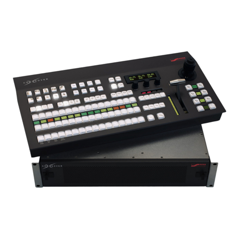
Carbonite eXtreme Second
Switcher Upgrade
Carbonite eXtreme can be upgraded to include two
independent switcher subsystems (switcher A and
switcher B). Each switcher subsystem has access to all
the inputs and outputs of the router subsystem. A router
output can only be assigned to a single switcher output.
This upgrade installs the Carbonite eXtreme CPU into
the second slot, and adds a number of cards to the system
to support the switcher.
Refer to the QuickStart poster that came with your
upgrade kit for information on cabling the control panel
and breakout box to the frame.
Caution: The upgrade of the Carbonite eXtreme
with a second switcher must be limited to service
personnel only and must be performed with the
frame/chassis in a de-energised state.
Important: The Carbonite eXtreme second
switcher upgrade is only compatible with
Carbonite eXtreme / NK-3G144-X frame
(2500AR-202-xx) running software version 8.0
or higher. If you do not have this frame or
software, or are unsure about the model of your
frame, please contact Ross Video Technical
Support for more information.
Upgrade Components
The Carbonite eXtreme upgrade kit contains the
following parts.
Table 1: Parts Description
DescriptionPart
Controller Card2500AR-003A
Switcher/Crosspoint Card4803AR-001A
USB Cable (12")30-00478
The Breakout Panel4803AR-050
The Breakout Panel cable70-00394
Ethernet Interface Card4803AR-070A
GPIO/Tally Card4803AR-072A
DescriptionPart
GPI/Tally Rear Module2500AR-025
The Carbonite eXtreme Product Resources
disk
4803CDR-004
Carbonite eXtreme Setup Manual4803DR-120
Carbonite eXtreme QuickStart4803DR-200
Carbonite eXtreme Hardware
Upgrade
The Carbonite eXtreme upgrade of the NK-3G144-X
frame requires the removal and installation of a number
of hardware components.
Caution: When the frame is energized,
Hazardous Energy Levels are present on the
chassis midplane where I/O card resettable fuses
make contact with the 15V DC supply bus.
Hazardous Energy Sources can cause fire or
serious burns under short circuit conditions.
Access to the inside chassis areas must be
restricted to service personnel only, by use of
the chassis door screw. The screw should be
engaged to limit access to the inside chassis
without a tool.
Caution: Servicing within the chassis while
energized should be limited to module card or
supply installation, or defect replacement.
Installation of the cards should be carried at the
front of the enclosure and care should be taken
to avoid any card or user contact with the
resettable fuses on the chassis’s midplane. All
other service or repair should be carried out
off-line with the chassis in a de-energized state.
To Install Carbonite eXtreme Frame CPU
(Switcher B)
Important: Only qualified service personnel are
allowed to replace or service system boards
and/or cards.
1. Power off the frame and open the frame door.
2. If there is an NK-3G144-X Matrix card in the
bottom slot, remove it.
4803DR-407-02
3. Install the Switcher/Crosspoint Card into the
bottom slot in the frame.
Figure 1: Switcher B Switcher/Crosspoint Card
Installation (Top Switcher/Crosspoint Card not
shown)
4. Install the retaining screws on the
Switcher/Crosspoint Card latches.
Figure 2: Retaining Screws
5. Connect the USB cable from the USB port on
the Switcher/Crosspoint Card to the USB 2 port
on the left side of the frame.
Figure 3: Switcher B Switcher/Crosspoint Card USB
To Install the Controller Card (Switcher B)
The Carbonite eXtreme uses the same rear module for
the Controller Card for both the Switcher/Crosspoint
Cards.
Important: Only qualified service personnel are
allowed to replace or service system boards
and/or cards.
1. Locate the Controller Card slot in the frame for
switcher B.
If there is a NK-3G144-X Controller Card
installed in the slot, it must be removed.
2
0 I
0 I
Controller Card
GPIO/Tally
Card Ethernet
Interface
Card
Figure 4: Controller Card Slot for Switcher B
2. Orient the new card so that the component side
is towards the power supplies.
3. Rotate the ejector tabs on the card out.
Figure 5: Controller Card Installation for Switcher
B
4. Align the card to the top and bottom guide rails
and insert the card into the slot until it is rmly
seated.
Warning: Do not use excessive force
to seat the card. If the card does not fit
into the slot, check the alignment of the
card and the rear module.
5. Rotate the ejector tabs in, towards the front of
the card, to lock the card into the slot.
To Install the Ethernet Interface Card and
GPIO/Tally Card (Switcher B)
Important: Only qualified service personnel are
allowed to replace or service system boards
and/or cards.
1. Remove the ve (5) screws securing the rear
module to the frame and remove the old rear
module.
Figure 6: Rear Module Screws
2. Align the connectors on the back of the
GPI/Tally Rear Module to the connectors on the
midplane at the back of the frame and insert the
rear module into the slot.
3. Re-install the screws into the new rear module
to secure it in position.
3
Figure 7: GPI/Tally Rear Module Screws
4. Locate the GPIO/Tally Card and Ethernet
Interface Card slots in the frame.
0 I
0 I
Controller Card
GPIO/Tally
Card Ethernet
Interface
Card
Figure 8: GPIO/Tally and Ethernet Card Slots for
Switcher B
5. Orient the Ethernet Interface Card so that the
component side is towards the power supplies.
6. Rotate the ejector tabs on the card out.
Figure 9: Ethernet Interface Card Installation for
Switcher B
7. Align the card to the top and bottom guide rails
and insert the card into the slot until it is rmly
seated.
Warning: Do not use excessive force
to seat the card. If the card does not fit
into the slot, check the alignment of the
card and the rear module.
8. Rotate the ejector tabs in, towards the front of
the card, to lock the card into the slot.
9. Install the GPIO/Tally Card in the same way as
the Ethernet Interface Card.
Ports for Switcher B
With the installation of the Ethernet Interface Card and
GPIO/Tally Card there are additional ports on the back
of the frame for connecting to switcher B. With the
exception of the ethernet ports, all the new ports on the
second rear module are dedicated to switcher B.
4
Figure 10: Switcher Ports
Router Inputs and Outputs
Video signals can either pass directly from an input BNC
on the router to an output BNC on the router, bypassing
the video processing of the switcher subsystem, or can
pass through the switcher subsystem. Only video signals
passing through the switcher can be used for transitions
or keying.
The Switchboard node in the DashBoard control system
allows you to assign video sources to the input and output
BNCs. The router subsystem views the switcher inputs
as outputs and the switcher outputs as inputs. These
inputs and outputs must be mapped to BNCs on the router
to allow video sources in and out of the switcher. The
router subsystem assigns a different range of inputs and
outputs to each switcher subsystem.
Note: You cannot route an output from one switcher subsystem
to the input of the other switcher subsystem. Each switcher
subsystem is an independent unit.
Switcher BSwitcher A
169-192145-168Router Outputs to
Switcher
155-164145-154Router Inputs from
Switcher
Note: Video signals that are routed through the switcher
subsystem are delayed versus those that are routed directly
from an input BNC to an output BNC.
Switchboard Setup
Before you can access the inputs and outputs of the
switcher you must congure Switchboard to access the
additional inputs and outputs.
To Set Up Switchboard
1. Open the Switchboard node in DashBoard for
your frame.
2. Click the Configure Switchboard button in
the upper-right corner of the window.
3. Select the Custom check box for the router the
switcher is installed into.
4. Click Yes on the Overwrite dialog box to
conrm the changes.
5. Clear the Custom and click Yes to conrm.
Switcher Inputs from the Router
Video inputs to the switcher must be assigned to outputs
(Switcher Input 1-24) on the router.
To Assign a Router Input to a Switcher Input
1. Open the Switchboard node in the DashBoard
control system for your frame.
2. In the Output column, select the switcher input
(Switcher A/B Input 1-24) that you want to
assign a router input to.
3. In the Input column, select the source from the
router (In 1-In 144) that you wan to assign to
the selected switcher input.
Switcher Outputs to the Router
Video outputs from the switcher must be assigned to
outputs on the router.
To Assign a Switcher Output to a Router Output
1. Open the Switchboard node in the DashBoard
control system for your frame.
5
2. In the Output column, select the output of the
router that you want to assign an output of the
switcher to.
3. In the Input column, select the output from the
switcher (switcher A or switcher B) that you
want to assign to a router output.
•Switcher A/B Preview — main preview
output of the switcher
•Switcher A/B Program — main program
output of the switcher
•Switcher A/B Output 1-8 — video outputs
from the switcher
•In1-In144 — router inputs (bypass switcher)
6

Other manuals for Carbonite eXtreme

1

Other Ross Switch manuals

Ross Vision Squeeze & Tease User manual

Ross

Ross Vision Squeeze & Tease User manual

Ross Synergy 1 SD User manual

Ross

Ross Synergy 1 SD User manual

Ross MC1-MK User manual

Ross

Ross MC1-MK User manual

Ross Carbonite Black Series User guide

Ross

Ross Carbonite Black Series User guide

Ross Synergy 1 SD User manual

Ross

Ross Synergy 1 SD User manual

Ross NK User manual

Ross

Ross NK User manual

Ross Carbonite Solo User manual

Ross

Ross Carbonite Solo User manual

Ross Carbonite Series User manual

Ross

Ross Carbonite Series User manual

Ross Synergy 1 SD User manual

Ross

Ross Synergy 1 SD User manual

Ross Synergy 1 SD User manual

Ross

Ross Synergy 1 SD User manual

Ross Carbonite Black Series User manual

Ross

Ross Carbonite Black Series User manual

Ross Carbonite Black Solo User manual

Ross

Ross Carbonite Black Solo User manual

Ross Ultrix Carbonite User manual

Ross

Ross Ultrix Carbonite User manual

Ross OpenGear DSS-8224 User manual

Ross

Ross OpenGear DSS-8224 User manual

Ross Synergy 1 SD User manual

Ross

Ross Synergy 1 SD User manual

Ross Carbonite Ultra User manual

Ross

Ross Carbonite Ultra User manual

Ross Carbonite Series User guide

Ross

Ross Carbonite Series User guide

Ross ACO-4400A User manual

Ross

Ross ACO-4400A User manual

Ross carbonite User guide

Ross

Ross carbonite User guide

Ross Synergy 2 SD User manual

Ross

Ross Synergy 2 SD User manual

Ross Synergy 1 SD User manual

Ross

Ross Synergy 1 SD User manual

Ross Synergy 1 SD User manual

Ross

Ross Synergy 1 SD User manual

Ross Acuity User manual

Ross

Ross Acuity User manual

Ross carbonite User manual

Ross

Ross carbonite User manual

Popular Switch manuals by other brands

Sunricher SR-ZGP2801K4-DIM-E instruction manual

Sunricher

Sunricher SR-ZGP2801K4-DIM-E instruction manual

Lindy 38030 user manual

Lindy

Lindy 38030 user manual

Milestone ML 201 KVM SS manual

Milestone

Milestone ML 201 KVM SS manual

AVS AHDSW41 user manual

AVS

AVS AHDSW41 user manual

MicroNet SP212D user manual

MicroNet

MicroNet SP212D user manual

D-Link DUB-9240 - UWB Wireless USB installation guide

D-Link

D-Link DUB-9240 - UWB Wireless USB installation guide

Intellinet 508261 instructions

Intellinet

Intellinet 508261 instructions

Broadcast Pix Slate 100 Operator's manual

Broadcast Pix

Broadcast Pix Slate 100 Operator's manual

Cisco Catalyst 9500 Series Hardware installation guide

Cisco

Cisco Catalyst 9500 Series Hardware installation guide

H3C S3100 Series Operation manual

H3C

H3C S3100 Series Operation manual

Extreme Networks Summit X150 Series Hardware installation guide

Extreme Networks

Extreme Networks Summit X150 Series Hardware installation guide

Comtech EF Data CRS-100 Operation manual

Comtech EF Data

Comtech EF Data CRS-100 Operation manual

Avocent CPS1610 Installer/user guide

Avocent

Avocent CPS1610 Installer/user guide

Lindy 32254 user guide

Lindy

Lindy 32254 user guide

Cisco Catalyst 2960 Series datasheet

Cisco

Cisco Catalyst 2960 Series datasheet

Girard Systems 98GCK-49B manual

Girard Systems

Girard Systems 98GCK-49B manual

Kinivo 550BN user manual

Kinivo

Kinivo 550BN user manual

ELC DT229 user manual

ELC

ELC DT229 user manual

manuals.online logo
manuals.online logoBrands
  • About & Mission
  • Contact us
  • Privacy Policy
  • Terms and Conditions

Copyright 2025 Manuals.Online. All Rights Reserved.