RS PRO RS 51 206-3722 User manual

2
INTRODUCTION
1-1 Unpacking and Inspection
Upon removin
g
y
our new Di
g
ital Thermometer from its packin
g
,
y
ou should have the followin
g
items:
1. Di
g
ital Thermometer.
2. K-t
y
pe Bead Thermocouple.
3. Operator's Manual.
4. Protective Holster.
5. Belt Clip.
1-2 Front Panel
Refer to Fi
g
ure 1 and the followin
g
numbered steps to familiarise
y
ourself with the meter's front panel controls and
connectors.
1. Digital Display — The di
g
ital displa
y
has a 3-1/2 di
g
it LCD readout (maximum readin
g
1999) auto polarit
y
decimal point, "
" , function symbol and unit annunciators.
2. Thermocouple Connectors — Allows connections of miniature thermocouple plugs (2 for model 52).
DIGITAL THERMOMETER
OPERATOR'S MANUAL
RS 51 206-3722
RS 52 206-3738

3
3. Hold Switch — Used to hold the numeric readin
g
. When pressed the HOLD annunciator is displa
y
ed.
Conversions are made but the readin
g
is not updated.
This switch is limited to use on a sin
g
le temperature scale at a time.
4. Power ON/OFF Switch — Turns the thermometer on or off.
5. Resolution Selector — Selects either 0.1 or 1 de
g
ree resolution.
6.
:
:
/
;
;
Selector — Used to select the °C and °F units.
7. Max. Switch — Press once to display the max. reading in measurements, press again to cancel.
Disable this function before changing control keys to keep reading correctly.
This switch is limited to use on a single temperature scale at a time.
8. T1-T2 Switch - Selects the T1-T2 mode for measuring (52 only).
9. T2 Switch - Selects the T2 mode for measuring (52 only).
10. T1 Switch - Selects the T1 mode for measuring (52 only).


5
SPECIFICATIONS
2-1 General Specifications
This Thermometer conforms to the temperature / volta
g
e tables of the National Bureau of Standards and to the IEC
Standards for K-t
y
pe.
Display: 3 1/2 di
g
it Liquid Cr
y
stal Displa
y
(LCD) with a maximum readin
g
of 1999.
Polarity Indication: Automatic, positive implied, ne
g
ative indicated.
Overrange Indication: "OL" or "-OL".
Low Battery Indication: "
" is displa
y
ed when the batter
y
volta
g
e drops below operatin
g
volta
g
e.
Sampling Rate: 2.5 time / sec.

6
2-2 Environmental Conditions
Operating Temperature: 0°C to 50°C, 0 to 75% R.H.
Storage Temperature: -20°C to 60°C, 0 to 80% R.H with batter
y
removed from meter.
Temperature Coefficient: 0.15 x (Specified accurac
y
) / °C, < 18°C or > 28°C.
Power Requirements: 9V alkaline batter
y
.
Battery Life: Alkaline 250 hours.
Dimensions (H x W x D): 160mm x 64mm x 26mm without holster.
170mm x 74mm x 39mm with holster.
Weight (including battery): 300
g
ms without holster.
430
g
ms with holster.
Accessories: 2 K-t
y
pe bead thermocouples (52), 1 K-t
y
pe bead thermocouple (51) batter
y
(installed), operator's
manual and protective holster.

7
2-3 Electrical Specifications
(1) Accurac
y
is ± (% readin
g
+ number of di
g
its) at 23°C ± 5°C less than 75% R.H for thermometer.
MODEL: 51
Measurement Range Resolution Accuracy Input Protection
-50°C ~ 199.9°C0.1°C ± (0.2% readin
g
+ 1°C)
-58°F ~ 199.9°F 0.1°F± (0.2% readin
g
+ 2°F)
-50°C ~ 200°C1°C ± (0.3% readin
g
+ 2°C)
-58°F ~ 392°F 1°F± (0.3% readin
g
+ 4°F)
200°C ~ 1000°C1°C ± (0.4% readin
g
+ 2°C)
392°F ~ 1832°F 1°F± (0.4% readin
g
+ 4°F)
1000°C ~ 1300°C1°C ± (0.6% readin
g
+ 2°C)
1832°F ~ 1999°F 1°F± (0.6% readin
g
+ 4°F)
60V d.c. or 24 Vr.m.s.

8
MODEL: 52
Input protection: 9V DC or 6V rms.
Measurement Range Resolution Accuracy (T1 or T2)
-50°C ~ 199.9°C0.1°C ± (0.2% readin
g
+ 1°C)
-58°F ~ 199.9°F 0.1°F± (0.2% readin
g
+ 2°F)
-50°C ~ 200°C1°C ± (0.3% readin
g
+ 2°C)
-58°F ~ 392°F 1°F± (0.3% readin
g
+ 4°F)
200°C ~ 1000°C1°C ± (0.4% readin
g
+ 2°C)
392°F ~ 1832°F 1°F± (0.4% readin
g
+ 4°F)
1000°C ~ 1300°C1°C ± (0.6% readin
g
+ 2°C)
1832°F ~ 1999°F 1°F± (0.6% readin
g
+ 4°F)
Accuracy (T1 — T2)
± (0.5% readin
g
+ 1°C)
± (0.5% readin
g
+ 4°F)
± (0.5% readin
g
+ 2°C)
± (0.5% readin
g
+ 4°F)
± (0.5% readin
g
+ 2°C)
± (0.5% readin
g
+ 4°F)
± (0.6% readin
g
+ 2°C)
± (0.6% readin
g
+ 4°F)

9
(2) Thermocouple Characteristics: K-t
y
pe thermocouple.
50BK bead thermocouple:
1. Temperature Ran
g
e : -40°C to 204°C (-40°F to 399.2°F).
2. Tolerances : ± (2.2°C or 0.75%) from 0°C to 204°C.
± (2.2°C or 2.0%) from 0°C to -40°C.
3. Wire Len
g
th : 1m, with miniature plu
g
.
Teflon tape insulated.
OPERATION
This instrument is desi
g
ned to use external K-t
y
pe thermocouple as temperature sensor. Temperature indication
follows National Bureau of Standards and IEC 584 temperature / volta
g
e tables for K-t
y
pe thermocouple are
supplied with thermometer.

10
#WARNING
TO AVOID ELECTRICAL SHOCK, DO NOT USE THIS INSTRUMENT WHEN VOLTAGES AT THE MEASURE-
MENT SURFACE EXCEED 24V RMS OR AC OR 60V DC. (6Vrms AC OR 9VDC FOR 52) TO AVOID DAMAGE
OR BURNS, DO NOT MAKE TEMPERATURE MEASUREMENTS IN MICROWAVE OVENS.
3-1 Preparation and Caution before Measurement
1. Before measurement, warm up for at least 30 seconds, after connectin
g
the thermocouple to the thermometer.
2. If the instrument is used near noise
g
eneratin
g
equipment, be aware that the displa
y
ma
y
become unstable
or indicate lar
g
e errors.
3-2 Temperature Measurements
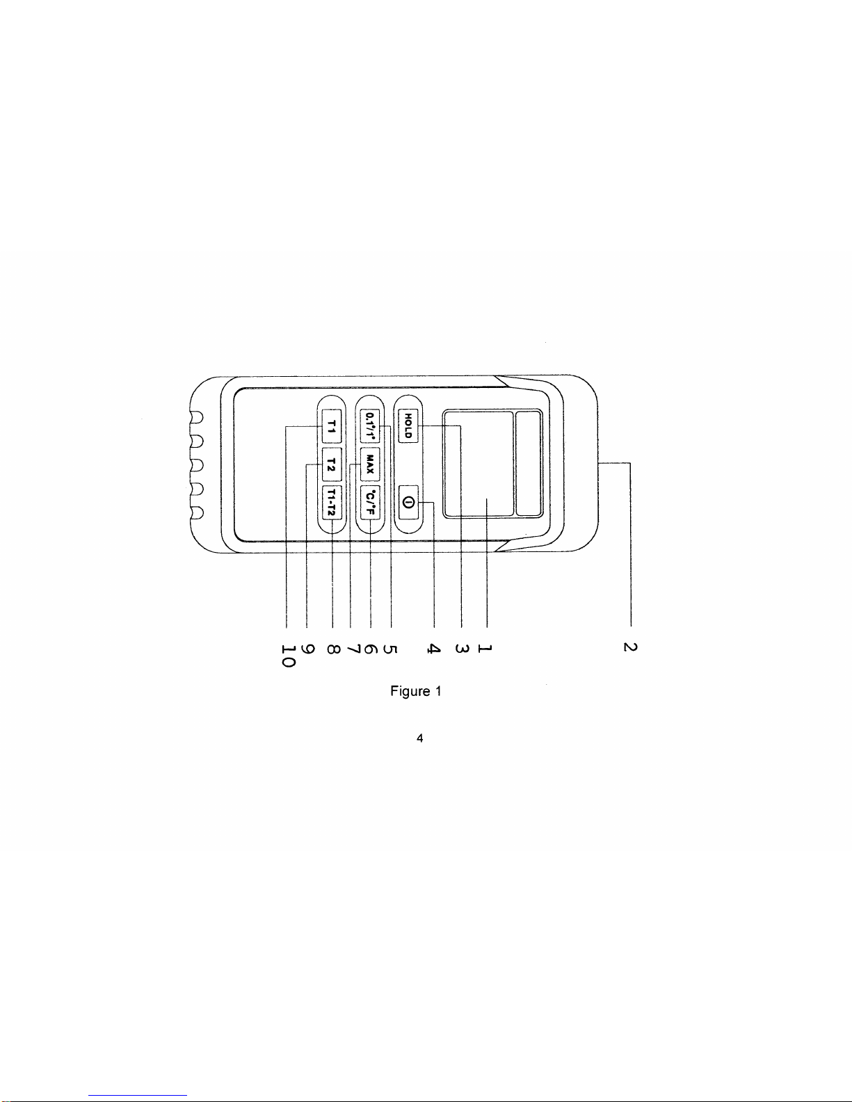
1. Connect the plu
g
of the thermocouple to the connector of the thermometer.
2. Select the desired input mode, resolution and °C/°F.
3. Use the sensin
g
point of the thermocouple to measure the surface to be measured.
4. Read the stable readin
g
.
5. #"Warnin
g
: Do not measure the surface if the potential exceeds 60 Vd.c. or 24Vr.m.s."

11
MAINTENANCE
To keep the instrument clean, wipe the case with a damp cloth and deter
g
ent, do not use abrasives or solvents.
An
y
adjustment, maintenance and repair shall be made b
y
a skilled person.
To maintain the thermocouple in
g
ood condition, observe the followin
g
precautions:
— Avoid excess bendin
g
.
— Do not overheat the thermocouple.
— Avoid chemical reactions that can dama
g
e the thermocouple.
BATTERY REPLACEMENT
The meter is powered b
y
a sin
g
le 9V batter
y
. Refer to Fi
g
ure 2 and use the followin
g
procedure to replace the
batter
y
:
1. Turn the meter off. Remove the thermocouple connector.
2. Remove the holster.
3. Position the meter face down. Remove the screw from the batter
y
cover.
4. Remove the batter
y
cover.
5. Lift the batter
y
from case top, and carefull
y
disconnect the batter
y
from batter
y
connector leads.
6. Install a new batter
y
.
7. Replace the batter
y
cover. Reinstall the screw and replace the holster.


United Kingdom
RS Components UK
PO Box 99, Corby
Northants NN17 9RS
Tel 01536 201234
Fax 01536 405678
France
Radiospares Composants
Rur Norman King, BP 453
60031 Beauvais Cedex
Tel +33 3 44 10 15 15
Fax +33 3 44 10 16 00
Italy
RS Components S.p.A.
Via Cadorna 66
20090, Vimodrone, Milano
Tel +39 2/27,425.1
Fax+39 2/27,425.207
Germany
RS Components GmbH
Hessenring 13b
64545 Morfelden-Walldrof
Tel +49 6105/401 –234
Fax +49 6105/401-100

THERMOMETRE NUMERIQUE
MANUEL DE L'UTILISATEUR
RS 51 206-3722
RS 52 206-3738

F2
INTRODUCTION
1-1 Déballage et inspection
Voici les articles qui devraient se trouver avec le thermomètre numérique lors de son déballa
g
e :
1. Thermomètre numérique.
2. Thermocouple à bille de t
y
pe K.
2. Manuel de l'utilisateur.
4. Etui protecteur.
5. Pince de ceinture
1-2 Panneau avant
Consulter la fi
g
ure 1 et les étapes numérotées suivantes pour se familiariser avec les commandes et les connec-
teurs du panneau avant du multimètre.
1. Affichage numérique — L'afficha
g
e numérique a un écran à cristaux liquides de 3 1/2 chiffres (lecture maximale
de 1999), auto-polarité et point décimal.
, symbole de fonction et avertisseurs
unitaires.
2. Connecteurs du thermocouple — Permet les connexions de prises de thermocouples miniatures

F3
3. Commutateur de retenue — Sert à retenir les lectures numériques. L'avertisseur HOLD apparaît quand on
appuie dessus. Les conversions sont faites, mais la lecture n'est pas mise à jour.
Ce commutateur est limité à un usa
g
e sur une seule pla
g
e de température à la
fois.
4. Interrupteur marche/arrêt — Allume et éteint le thermomètre.
5. Sélecteur de résolution — Sélectionne une résolution de 0,1 ou de 1 de
g
ré.
6. °Sélecteur °C / °F — Sert à sélectionner les degrés °C et °F.
7. Commutateur maximum — Appuyer une fois pour afficher la lecture maximale en mesures, appuyer de
nouveau
pour annuler. Invalider cette fonction avant de changer les touches de commande
pour maintenir la lecture correcte.
Ce commutateur est limité à un usage sur une seule plage de température à la fois.
8. Commutateur T1-T2 - Sélectionne le mode T1-T2 pour mesurer (52 seulement).
9. Commutateur T2 - Sélectionne le mode T2 pour mesurer (52 seulement).


F5
SPECIFICATIONS
2-1 Spécifications générales
Ce thermomètre est conforme aux tableaux de températures/tensions du Bureau national des Normes et aux
normes de l'IEC pour les t
y
pes K.
Affichage : Ecran à cristaux liquides de 3 1/2 chiffres avec une lecture maximale de 1999.
Indication de la polarité : Automatique, positive implicite et né
g
ative indiquée.
Indication de dépassement : OL ou -OL.
Indication de basse tension de batterie :"
" est affiché quand la tension de la batterie chute en dessous de la
tension de fonctionnement.
Cadence d'échantillonnage : 2,5 fois par seconde.

F6
2-2 Conditions environnementales
Température d'utilisation : 0°C à 50°C, humidité relative de 0 à 75 %.
Température de stockage : -20°C à 60°C, humidité relative de 0 à 80 % avec la pile enlevée du multimètre.
Coefficient de température : 0,15 x (précision spécifiée) / °C, < 18°C ou > 28°C.
Exigences électriques : Pile alcaline de 9 V.
Durée de la pile : Alcaline 250 heures.
Dimensions (haut. x larg. x prof.) : 160 mm x 64 mm x 26 mm, sans l'étui.
170 mm x 74 mm x 39 mm, avec l'étui.
Poids (piles comprises) :
300
g
rammes sans l'étui.
430
g
rammes avec l'étui.
Accessoires : 2 thermocouples à bille de t
y
pe K (52), 1 pile de thermocouple à bille de t
y
pe K (posée) (51),

F7
2-3 Spécifications électriques
(1) La précision est de ± (% de lecture + nombre de chiffres) à 23°C ± 5°C, humidité relative inférieure à 75 %
poule thermomètre.
MODELE : 51
Plage de mesure Résolution Précision Protection d'entrée
-50°C ~ 199.9°C0.1°C ± (lecture de 0.2 % + 1°C)
-58°F ~ 199.9°F 0.1°F± (lecture de 0.2 % + 2°F)
-50°C ~ 200°C1°C ± (lecture de 0.3 % + 2°C)
-58°F ~ 392°F 1°F± (lecture de 0.3 % + 4°F)
200°C ~ 1000°C1°C ± (lecture de 0.4 % + 2°C)
392°F ~ 1832°F 1°F± (lecture de 0.4 % + 4°F)
1000°C ~ 1300°C1°C ± (lecture de 0.6 % + 2°C)
1832°F ~ 1999°F 1°F± (lecture de 0.6 % + 4°F)
60 V c.c. ou 24 V rms
This manual suits for next models
1
Table of contents
Languages:
Other RS PRO Thermometer manuals

RS PRO
RS PRO RS-8806S User manual

RS PRO
RS PRO RS-40 User manual

RS PRO
RS PRO RS-1327 User manual

RS PRO
RS PRO RS 1710 User manual

RS PRO
RS PRO RS-820 User manual

RS PRO
RS PRO RS-8806S User manual

RS PRO
RS PRO RS-836 User manual

RS PRO
RS PRO 1327K User manual

RS PRO
RS PRO RS-325 User manual

RS PRO
RS PRO IR-95 User manual