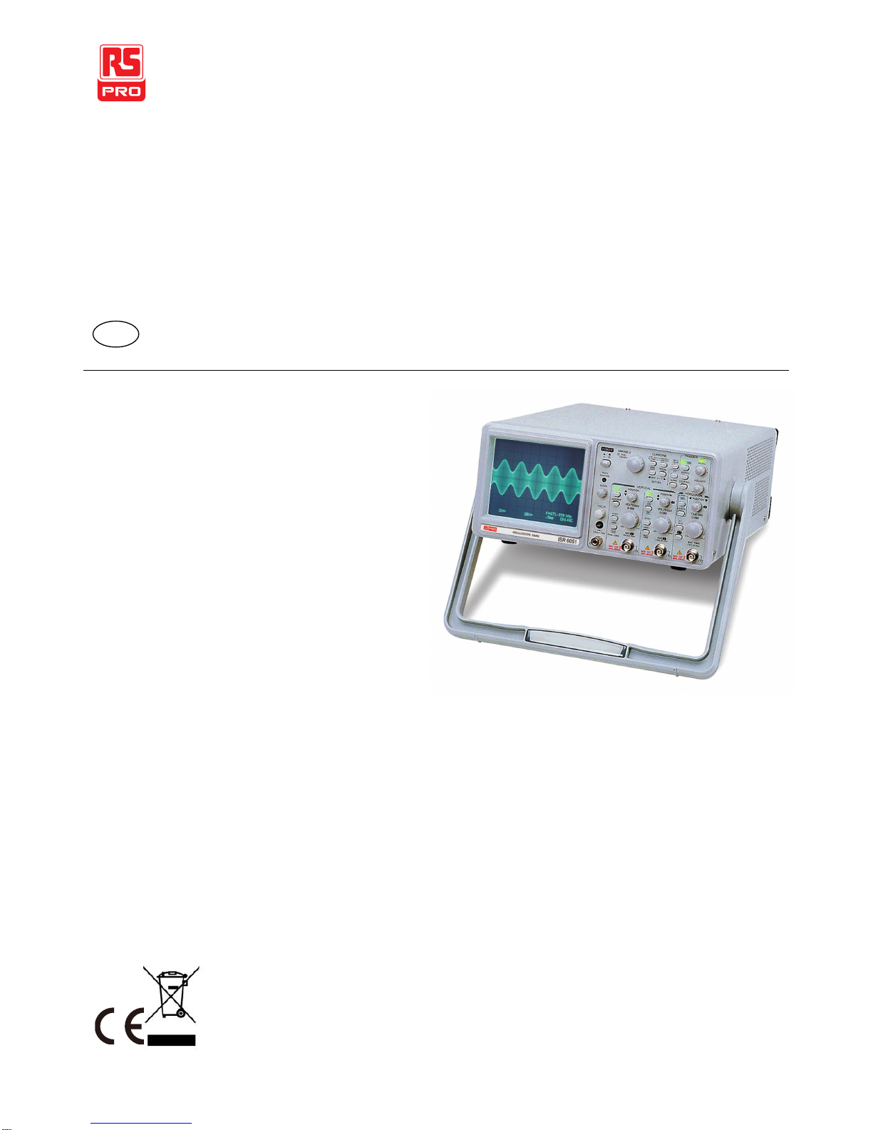
ISR-6051 OSCILLOSCOPE
USER MANUAL
CONTENTS PAGE
1.PRODUCTINTRODUCTION .................................................................. 1
1-1. DESCRIPTION............................................................................................. 1
1-2. FEATURES .................................................................................................2
2.TECHNICAL SPECIFICATIONS............................................................ 4
3.PRECAUTIONSBEFOREOPERATION.............................................. 7
3-1. UNPACKING THEOSCILLOSCOPE.............................................................. 7
3-2. CHECKINGTHESUPPLYVOLTAGE............................................................ 7
3-3. ENVIRONMENT.......................................................................................... 8
3-4. EQUIPMENTINSTALLATION AND OPERATION.......................................... 8
3-5. CRT INTENSITY......................................................................................... 8
3-6. MAXIMUMWITHSTANDVOLTAGEOFINPUTTERMINALS........................ 8
4.FRONTAND REARPANELS................................................................... 9
4-1. FRONTPANEL..........................................................................................11
4-2. REARPANEL........................................................................................... 26
5.OPERATION............................................................................................... 28
5-1. READOUTDISPLAY ................................................................................. 28
5-2. CONNECTING INPUTSIGNALS.................................................................30
5-3.ADJUSTMENTSANDCHECKS...................................................................31
5-4. FUNCTION CHECK................................................................................... 33
5-5. BASICOPERATION...................................................................................36
5-6. MEASUREMENTAPPLICATIONS..............................................................45
6.MAINTENENCE........................................................................................ 47
6-1. FUSEREPLACEMENT .............................................................................. 47
6-2. LINEVOLTAGECONVERSION..................................................................47
6-3. CLEANING............................................................................................... 48
7.BLOCKDIAGRAM...................................................................................49
i