Ruijie Reyee RG-EST100-E User manual

Ruijie Reyee Series Wireless Bridge
Implementation Cookbook
Document Version: V1.3
Date: 2023.07.20
Copyright © 2023 Ruijie Networks

Copyright
Copyright © 2023 Ruijie Networks
All rights are reserved in this document and this statement.
Without the prior written consent of Ruijie Networks, any organization or individual shall not reproduce, extract,
back up, modify, or propagate the content of this document in any manner or in any form, or translate it into other
languages or use some or all parts of the document for commercial purposes.
, and other Ruijie networks logos are trademarks of Ruijie Networks.
All other trademarks or registered trademarks mentioned in this document are owned by their respective owners.
Disclaimer
The products, services, or features you purchase are subject to commercial contracts and terms, and some or
all of the products, services, or features described in this document may not be available for you to purchase or
use. Except for the agreement in the contract, Ruijie Networks makes no explicit or implicit statements or
warranties with respect to the content of this document.
The content of this document will be updated from time to time due to product version upgrades or other reasons,
Ruijie Networks reserves the right to modify the content of the document without any notice or prompt.
This manual is designed merely as a user guide. Ruijie Networks has tried its best to ensure the accuracy and
reliability of the content when compiling this manual, but it does not guarantee that the content of the manual is
completely free of errors or omissions, and all the information in this manual does not constitute any explicit or
implicit warranties.

I
Preface
Intended Audience
This document is intended for:
Network engineers
Technical support and servicing engineers
Network administrators
Technical Support
The official website of Ruijie Reyee: https://www.ruijienetworks.com/products/reyee
Technical Support Website: https://www.ruijienetworks.com/support
Case Portal: https://caseportal.ruijienetworks.com
Community: https://community.ruijienetworks.com
Technical Support Email: [email protected]
Conventions
1. GUI Symbols
Interface
symbol
Description
Example
Boldface
1. Button names
2. Window names, tab name, field name and
menu items
3. Link
1. Click OK.
2. Select Config Wizard.
3. Click the Download File link.
>
Multi-level menus items
Select System >Time.
2. Signs
This document also uses signs to indicate some important points during the operation. The meanings of these
signs are as follows:
Warning
An alert that calls attention to important rules and information that if not understood or followed can result in
data loss or equipment damage.
Note
An alert that calls attention to essential information that if not understood or followed can result in function
failure or performance degradation.
Instruction
An alert that contains additional or supplementary information that if not understood or followed will not lead to
serious consequences.

II
Specification
An alert that contains a description of product or version support.
3. Instruction
This manual is used to guide users to understand the product, install the product, andcomplete the configuration.
The example of the port type may be different from the actual situation. Please proceed with configuration
according to the port type supported by the product.
The example of display information may contain the content of other product series (such as model and
description). Please refer to the actual display information.
The routers and router product icons involved in this manual represent common routers and layer-3
switches running routing protocols.

i
Contents
Preface...................................................................................................................................................I
1 Product Introduction...........................................................................................................................1
1.1 RG-EST100-E............................................................................................................................1
1.1.1 Appearance....................................................................................................................1
1.1.2 Device Specification.......................................................................................................2
1.1.3 Ports and WPS Hole......................................................................................................4
1.2 RG-EST310 V2..........................................................................................................................6
1.2.1 Appearance....................................................................................................................6
1.2.2 Device Specification.......................................................................................................7
1.2.3 Port & Button..................................................................................................................8
1.3 RG-EST350 V2..........................................................................................................................9
1.3.1 Appearance....................................................................................................................9
1.3.2 Device Specification.....................................................................................................11
1.3.3 Port & Button .............................................................................................................12
2 Installation........................................................................................................................................14
2.1 Safety Suggestions..................................................................................................................14
2.1.1 Installation....................................................................................................................14
2.1.2 Movement ....................................................................................................................14
2.1.3 Electricity......................................................................................................................14
2.1.4 Static Discharge Damage Prevention..........................................................................14
2.1.5 Laser............................................................................................................................15
2.2 Installation Site Requirement...................................................................................................15

ii
2.2.1 Ventilation.....................................................................................................................15
2.2.2 Temperature and Humidity...........................................................................................15
2.2.3 Cleanness....................................................................................................................15
2.2.4 Grounding ....................................................................................................................15
2.2.5 EMI...............................................................................................................................16
2.3 Installing the Device.................................................................................................................16
2.3.1 Installation Tools...........................................................................................................16
2.3.2 Before Installation........................................................................................................17
2.3.3 Precautions..................................................................................................................17
2.3.4 Wall Mounting (Connection with Cables inAdvance)..................................................17
2.3.5 Pole Mounting..............................................................................................................18
3 Device Management........................................................................................................................20
3.1 Logging In to the Device..........................................................................................................20
3.2 Configuring Management Password .......................................................................................20
3.3 Setting the System Time..........................................................................................................21
3.4 Configuring Backup and Import...............................................................................................22
3.5 Restoring Factory Settings ......................................................................................................23
3.6 Setting the Session Timeout....................................................................................................23
3.7 Upgrade...................................................................................................................................24
3.7.1 Online Upgrade............................................................................................................24
3.7.2 Local Upgrade..............................................................................................................25
3.7.3 Upgrading All Devices..................................................................................................25
3.8 Restart......................................................................................................................................26
4 Configuration....................................................................................................................................27

iii
4.1 Overview..................................................................................................................................27
4.1.1 Setting the Address of a LAN Port for a Single Online Bridge ....................................27
4.1.2 Setting the WDS SSID.................................................................................................29
4.1.3 PTMP...........................................................................................................................30
4.2 LAN..........................................................................................................................................35
4.3 Wireless ...................................................................................................................................36
4.3.1 WDS.............................................................................................................................36
4.3.2 Region..........................................................................................................................37
4.4 Diagnostics ..............................................................................................................................38
4.4.1 Network Tools...............................................................................................................38
4.4.2 Fault Collection ............................................................................................................39
5 Reyee FAQs.....................................................................................................................................41
5.1 Reyee Password FAQ.............................................................................................................41
5.2 Reyee EST Bridge FAQ...........................................................................................................41
5.3 Reyee Series Devices Parameters Tables..............................................................................41
5.4 Reyee Parameter Consultation FAQ.......................................................................................41
6 Appendix: Monitoring........................................................................................................................42
6.1 Overview..................................................................................................................................42
6.1.1 NVR and Camera.........................................................................................................42
6.1.2 Alarm............................................................................................................................43
6.2 WDS Group Information ..........................................................................................................45
6.2.1 IPAllocation .................................................................................................................46
6.2.2 Configuring the SSID...................................................................................................48
6.2.3 Displaying Information About a Single Device.............................................................48

Implementation Cookbook Product Introduction
1
1 Product Introduction
1.1 RG-EST100-E
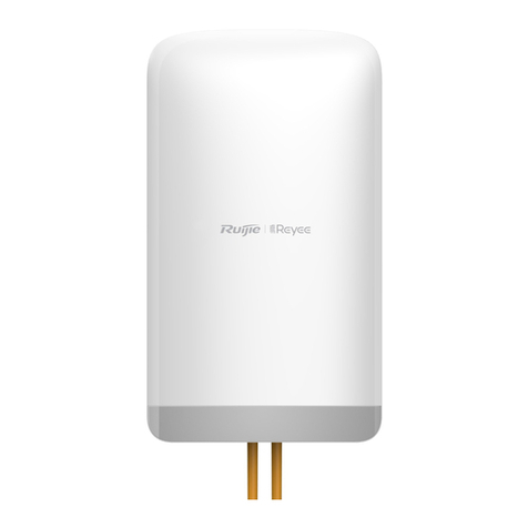
The RG-EST100-E is a dual-stream wireless bridge launched by Ruijie Reyee for the scenario of surveillance
video backhaul. Compliant with the IEEE 802.11n standard, the wireless bridge can work in the 2.4 GHz radio
and delivers a maximum data rate of 300 Mbps.
1.1.1 Appearance
Front View
Rear View

Implementation Cookbook Product Introduction
2
1.1.2 Device Specification
Table 1-1 Specification
Radio Design
Single-radio and dual-stream
Standard & Protocol
IEEE 802.11n
Operating Frequency
802.11b/g/n: 2.4000 GHz to 2.483 GHz
Note: The operating radio is country-specific.
Antenna Type
Built-in directional antenna
Lobe Angle
Horizontal lobe angle of 70°and vertical lobe angle of 70°
Antenna Gain
6 dBi
Spatial Streams
2.4 GHz: 2 x 2 MIMO
Max. Data Rate
2.4 GHz: 300 Mbps
Modulation
OFDM: BPSK@6/9 Mbps, QPSK@12/18 Mbps, 16-QAM@24 Mbps, and 64-
QAM@48/54 Mbps
OFDM: BPSK, QPSK, 16QAM, and 64QAM

Implementation Cookbook Product Introduction
3
Receiver Sensitivity
11b: –91 dBm (1 Mbps), –88 dBm (5 Mbps), –85 dBm (11 Mbps)
11a/g: –89 dBm (6 Mbps), –80 dBm (24 Mbps), –76 dBm (36 Mbps), –71 dBm (54
Mbps)
11n: –83 dBm@MCS0, –65 dBm@MCS7, –83 dBm@MCS8, –65 dBm@MCS15
Max. Transmit Power
100mw
Power Adjustment
Configurable in increments of 1 dBm
Dimensions (W x D x
H)
165.5 mm x 68.7 mm x 42 mm (6.52 in. x 2.70 in. x 1.65 in.)
Weight
0.30 kg (0.66 lbs.)
Service Port
Two 10/100Base-T Ethernet ports (LAN1 supports 12 V passive PoE power supply.)
Management Port
N/A
Status LED
One system status LED
Two LAN status LEDs
Three RSSI LEDs
Power Supply
a. 12 V passive PoE power supply (A passive PoE adapter is delivered with the
wireless bridge.)
b. 12 V DC power supply (A 12 V DC power adapter is delivered with the wireless
bridge.)
Max. Power
Consumption
5 W
Temperature
Working Temperature: –30°C to +60°C (–22°F to +140°F)
Storage Temperature: –40°C to +70°C (–40°F to +158°F)
Humidity
Working Humidity: 5% to 95% (non-condensing)
Storage Humidity: 5% to 95% (non-condensing)
Installation Method
Wall mounting and pole mounting (Hose clamps are delivered with the wireless
bridge.)
Certification
CE
MTBF
> 400,000 hours
Caution
In a domestic environment, this product may cause radio interference in which case the user may be required
to take adequate measures.

Implementation Cookbook Product Introduction
4
1.1.3 Ports and WPS Hole
Table 1-2 Ports & WPS Hole
No.
Ports and WPS Hole
Description
1
12 V DC Connector
12 V DC/1 A power supply
2
LAN1/PoE
10/100Base-T Ethernet port, supporting 12 V
passive PoE power supply
3
LAN2
10/100Base-T Ethernet port
4
WPS Hole
Press and hold the pin to the WPS hole for
less than 10 seconds: No action is triggered.
Press and hold the pin to the WPS hole for at
least 10 seconds: Restore the wireless bridge
to factory settings.

Implementation Cookbook Product Introduction
5
Table 1-3 LED
No,
LED
Status
Description
1
RSSI LEDs
STR1 on
–78 dBm < RSSI < –72 dBm
STR1 and STR2
on
–72 dBm < RSSI < –65 dBm
STR1, STR2, and
STR3 on
RSSI > –65 dBm
Blinking
RSSI < –78 dBm
Off
The device is not bridged.
2
LAN1/LAN2
Port Status
LED
Solid on
The LAN port is connected and not receiving or transmitting
data.
Blinking
The LAN port is connected and receiving or transmitting data.

Implementation Cookbook Product Introduction
6
No,
LED
Status
Description
3
System
Status LED
Off
The device is not powered on.
Fast blinking
Possible cases:
1. Restoring the wireless bridge to factory settings.
2. Upgrading the firmware.
3. Handling alarms automatically.
4. Starting up the wireless bridge.
Solid on
The device is working properly.
1.2 RG-EST310 V2
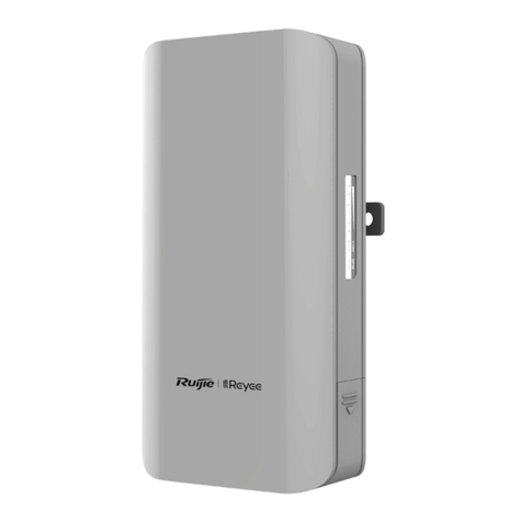
The RG-EST310 V2 is an 802.11ac wireless bridge launched by Ruijie Reyee. It provides services such as
surveillance video backhaul and wireless remote transmission in elevators, tower cranes, factories, parks,
construction sites and other scenarios. RG-EST310 V2 works in the 5GHz frequency band, supports two spatial
streams and 2 x 2 MIMO, and provides a wireless transmission speed of up to 867Mbps, which is sufficient to
meet the bandwidth requirements of user services for data links.
1.2.1 Appearance
Front View
Rear View

Implementation Cookbook Product Introduction
7
1.2.2 Device Specification
Table 1-4 Specification
Radio Design
Single-Frequency Dual-Stream
Transmission
Protocol
802.11 a/n/ac
Operating Frequency
802.11a/n/ac: 5.150-5.350GHz, 5.470-5.725GHz, 5.725-5.850GHz
United States:802.11a/n/ac:5.180~5.240GHz , 5.745~5.825GHz
Antenna Type
Built-in Directional Antenna, Horizontal 60°, Vertical 30°
Spatial Streams
2
Max Throughput
The 5GHz frequency band provides a wireless transmission speed of up to
867Mbps.
Modulation Types
OFDM: BPSK@6/9Mbps, QPSK@12/18Mbps, 16-QAM@24Mbps, 64-
QAM@48/54Mbps
OFDM: BPSK, QPSK,16QAM, 64QAM, 256QAM
Receiver sensitivity
802.11a: -89 dBm (6 Mbps), -80 dBm (24 Mbps), -76 dBm (36 Mbps), -71 dBm (54
Mbps)
802.11n: -83 dBm@MCS0, -65 dBm@MCS7, -83 dBm@MCS8, -65 dBm@MCS15
802.11ac: -86 dBm(MCS0), -63 dBm(MCS9)

Implementation Cookbook Product Introduction
8
Max Transmit Power
400mw (26dBm) (Single-Stream)
Transmit Power
Adjustment
1 dBm
Dimensions (L x W x
H, without bracket)
147 mm ×76 mm ×37 mm (5.78 in. x 2.99 in. x 1.46 in.)
Weight
0.35 kg (0.77 lbs.)
Service Ports
One 10/100BASE-T port, supporting 24 V non-standard PoE power supply
Management Ports
N/A
Status LED
One system LED, one Ethernet port LED, and three signal LEDs
Power Supply
Method
12 VDC and 24 V non-standard PoE power supply
Max Power
Consumption
7 W
Bluetooth 5.0
Not supported
Temperature
Operating Temperature: -30°C to 55°C (-22°F to 131°F)
Storage Temperature: -40°C to 70°C (-40°F to 158°F)
Operating Humidity: 5% to 95% RH (non-condensing)
Storage Humidity: 5% to 95% RH (non-condensing)
Installation Methods
Wall Mounting/Pole Mounting
Certification
CE
MTBF
>400000H
1.2.3 Port & Button
Table 1-5 Ports and Buttons
Item
Description
12 V DC port
Support 12 V/1 A DC power supply

Implementation Cookbook Product Introduction
9
Item
Description
LAN port
10/100Base-T Ethernet port with auto negotiation, supporting 24 V PoE
Reset button
Press the button for less than 2 seconds, and the device will be rebooted.
Press the button for over 5 seconds, and the device will be reset.
Table 1-6 LED Description
LED
Status
Description
System Status
LED
Off
System is not powered on.
Solid On
Initiation process is complete.
Slow Blinking
System is working but there is an alert.
Fast Blinking
System is being initialized.
Port Status LED
Solid On
The LAN port is not receiving or transmitting data.
Blinking
The LAN port is receiving or transmitting data.
Signal LED
LED 1 is solid on.
-73 dBm< RSSI <-59 dBm
LED 1 and LED 2
are solid on.
RSSI > -59 dBm
LED 1, LED 2 and
LED 3 are solid on.
RSSI > -49 dBm
Off
There is no signal.
1.3 RG-EST350 V2
The RG-EST350 V2 is an 802.11ac wireless bridge launched by Ruijie Reyee. It provides surveillance video
backhaul function. RG-EST350 V2 works in the 5GHz frequency band, supports two spatial streams and 2 x 2
MIMO, and provides a wireless link speed of up to 866.7Mbps. The design of RG-EST350 V2 adapts toinclement
outdoor environments such as the cold and humidity. This substantially simplifies installation and maintenance.
1.3.1 Appearance
Front View

Implementation Cookbook Product Introduction
10
Rear View

Implementation Cookbook Product Introduction
11
1.3.2 Device Specification
Table 1-7 Specification
Radio Design
Single-Frequency Dual-Stream
Transmission
Protocol
802.11 a/n/ac
Operating Frequency
802.11a/n/ac: 5.150-5.350GHz, 5.470-5.725GHz, 5.725-5.850GHz
United States:802.11a/n/ac:5.180~5.240GHz , 5.745~5.825GHz
Antenna Type
Built-in Directional Antenna
Bridging Distance
5 km
Spatial Streams
2 x 2MIMO
Max Throughput
The 5GHz frequency band provides a wireless link speed of up to 866.7Mbps.
Modulation Types
OFDM: BPSK@6/9Mbps, QPSK@12/18Mbps, 16-QAM@24/36Mbps, 64-
QAM@48/54Mbps
MIMO-OFDM: BPSK, QPSK, 16-QAM, 64-QAM, 256-QAM
Receiver sensitivity
11a: -89dBm(6Mbps), -80dBm(24Mbps), -76dBm(36Mbps), -71dBm(54Mbps)
11n: -83dBm@MCS0, -65dBm@MCS7, -83dBm@MCS8, -65dBm@MCS15
11ac VHT20: -83dBm(MCS0), -57dBm(MCS9)
11ac VHT40: -79dBm(MCS0), -57dBm(MCS9)
11ac VHT80: -76dBm(MCS0), -51dBm(MCS9)
Max Transmit Power
400 mw (26 dBm) (adjustable)
Transmit Power
Adjustment
1 dBm
Dimensions (L x W x
H, without bracket)
230 mm x 132 mm x 48 mm (9.05 in. x 5.19 in. x 1.89 in.)
Weight
0.5 kg (1.1 lbs.)
Service Ports
Two 10/100/1000BASE-T Ethernet ports, LAN1/PoE port supports 24 V PoE power
supply
Button
One reset button
Status LED
One system status LED, two LAN port status LEDs and three RSSI LEDs
Power Supply
Method
12 V/1 A DC and 24 V/0.5 A PoE power supply
Max Power
Consumption
10 W

Implementation Cookbook Product Introduction
12
Temperature
Working Temperature: -30°C to 65°C (-22°F to 149°F)
Storage Temperature: -40°C to 85°C (-40°F to 185°F)
Humidity
Working Humidity: 5% to 95% (non-condensing)
Storage Humidity: 5% to 95% (non-condensing)
Installation Methods
Wall Mounting/Pole Mounting
Certification
CE
MTBF
>250000H
Note
The weight refers to the weight of the main unit.
1.3.3 Port & Button
Figure 1-1 Port

Implementation Cookbook Product Introduction
13
Table 1-8 Port
No.
LED, Button and Port
Meaning
1
Status LED
6 status LEDs (1 system status LED, 2 LAN port status
LEDs and 3 RSSI LEDs)
2
12 V DC Port
Support 12 V/1 A DC power supply
3
LAN2 Port
10/100/1000Base-T Ethernet port
4
LAN1/PoE Port
10/100/1000Base-T Ethernet port, support 24 V/0.5 A
PoE
5
Reset Button
Press the button for less than 2 seconds, and the
device will be rebooted.
Press the button for over 5 seconds, and the
device will be reset.
Table 1-9 LED
LED
State
Meaning
System
Status
Solid green
The device is working properly.
Blinking green
The system is initializing, restoring factory settings, upgrading or
resetting.
Off
The device is not powered on.
LAN1/LAN
2 Port
Status
Solid green
The LAN port is link up and not receiving or transmitting data.
Blinking green
The LAN port is link up and receiving or transmitting data.
Off
The LAN port is not connected.
STR [1:3]
RSSI (3
LEDs in
Total)
STR1 blinking/on
The device is bridged.
STR1 on
RSSI > -75 dBm
STR1 on + STR2
blinking
RSSI > -73 dBm
STR1 on + STR2 on
RSSI > -71 dBm
STR1 on + STR2 on +
STR3 blinking
RSSI > -68 dBm
STR1 on + STR2 on +
STR3 on
RSSI > -64 dBm
Other manuals for Reyee RG-EST100-E
1
This manual suits for next models
1
Table of contents
Other Ruijie Network Hardware manuals

Ruijie
Ruijie Reyee RG-EST Series How to use

Ruijie
Ruijie RG-WALL1600-S3200 Installation and operating manual

Ruijie
Ruijie Reyee RG-EST310 Installation and operating manual

Ruijie
Ruijie Reyee RG-EST Series Dimensions

Ruijie
Ruijie Reyee RG-EST Series User manual

Ruijie
Ruijie RG-WALL 1600-Z3200-S Installation and operating manual

Ruijie
Ruijie Reyee RG-EST Series User manual

Ruijie
Ruijie RG-WS6512-L Installation and operating manual

Ruijie
Ruijie RG-EST350 Series Installation and operating manual

Ruijie
Ruijie Reyee RG-NBR6215-E User manual