Rupes SM43N Manual

SM43N
Smerigliatrice verticale
Vertical grinder
Meuleuse verticale
Vertikalschleifer
Amoladora vertical
Verticale slijper
Вертикальная шлифовальная машина
ISTRUZIONI PER L'USO E LA MANUTENZIONE
OPERATING AND MAINTENANCE INSTRUCTIONS
NOTICE D'EMPLOI ET D'ENTRETIEN
BEDIENUNGS-UND WARTUNGSANLEITUNG
INSTRUCCIONES DE USO Y MANUTENCION
AANWIJZINGEN VOOR HET GEBRUIK EN HET ONDERHOUD
ИНСТРУКЦИЯ ПО ЭКСПЛУАТАЦИИ И ОБСЛУЖИВАНИЮ
RUPES S.p.A.
Via Marconi, 3A
20080 VERMEZZO (Mi) - Italy
Tel. 02/946941
Fax 02/94941040
Uff. Vendite e assistenza clienti
Tel. 02/94694312
web: http://www.rupes.it
COD. ART. 9.2404 - MARZO 2014
4
8
12
16
20
24
28
Leggere tutte queste istruzioni prima di azionare il
presente prodotto.
Indicazioni importanti per la sicurezza dell’utilizzatore
Lesen Sie zuerst die folgenden Anweisung bevor Sie das
Gerät bedienen.
Wichtige Sicherheitsangaben
Antes de accionar este producto es necesario leer todas
estas instrucciones
Indicaciones importantes para la seguridad del usuario
Lees de volgende instructie voor u het product gebruikt
Belangrijke veiligheids instructies
Следует прочитать все эти инструкции прежде, чем
приводить овку.
Важные указания для безопасности пользователя
Lire toutes ces instructions avant d’actionner
le présent produit.
Indications importantes pour la sécurité de l’utilisateur
Read the following instruction first before operate
the product
Important safety indications
ISTRUZIONI ORIGINALI PER L'USO
E LA MANUTENZIONE
ORIGINAL OPERATING AND
MAINTENANCE INSTRUCTIONS
NOTICE ORIGINAL D'EMPLOI ET
D'ENTRETIEN
ORIGINAL-BEDIENUNGS-UND
WARTUNGSANLEITUNG
INSTRUCCIONES ORIGINAL DE
USO Y MANUTENCION
AANWIJZINGEN VOOR HET
GEBRUIK EN HET ONDERHOUD
ORIGINEEL
ИНСТРУКЦИЯ ПО ЭКСПЛУАТАЦИИ
И ОБСЛУЖИВАНИЮ1
ОРИГИНАЛЬНЫЙ
op SM43N MARZO 2014 cop_copertina sm43.qxd 02/04/2014 11.40 Pagina 1

1
4
10
11
12
13
3
2
5
4
6
7
8
3
9
4
4
DATI TECNICI ITALIANO
MODELLO
CLASSE DI PROTEZIONE
POTENZA ASSORBITA
GIRI/min
DIAMETRO MOLA/PLATORELLO PORTADISCO ABRASIVO mm
MASSA kg
SM43N
II
1.100 W
4.200
178
4,2
AVVERTENZE GENERALI
Le istruzioni per la sicurezza e la prevenzione degli infortuni sono
riportate nel fascicolo “INDICAZIONI PER LA SICUREZZA” che costituisce
parte integrante della presente documentazione. Il presente MANUALE
D’ISTRUZIONI per l’uso riporta solamente le informazioni aggiuntive
strettamente correlate all’uso specifico della macchina.
UTILIZZO CONFORME AGLI SCOPI PREVISTI
Questo utensile è destinato a funzionare come smerigliatrice. Leggere tut-
ti gli avvertimenti di sicurezza, le istruzioni, le illustrazioni e le specifiche
forniti con questo utensile. Il mancato rispetto di tutte le istruzioni sotto ri-
portate può causare una scossa elettrica, un incendio e/o un incidente grave.
Le operazioni di levigatura, spazzolatura metallica e lucidatura non sono
consigliate con questo utensile. Le operazioni per le quali non è previsto
l’utensile possono provocare un pericolo e causare danni alle persone.
Non utilizzare accessori non specificatamente realizzati per l’uso previsto
o non consigliati dal produttore. Il semplice fatto che l’accessorio possa
essere fissato al vostro utensile non garantisce un funzionamento in tutta
sicurezza.
La velocità nominale dell’accessorio deve essere almeno pari alla veloci-
tà massima indicata sull’utensile. Gli accessori fatti funzionare a una veloci-
tà superiore a quella nominale possono rompersi ed essere proiettati in
aria.
Il diametro esterno e lo spessore del vostro accessorio devono essere
adatti alle caratteristiche di capacità della protezione di sicurezza del vo-
stro utensile. Gli accessori che hanno dimensioni non corrette non possono
essere protetti o controllati adeguatamente.
La conformazione delle mole o di qualsiasi altro accessorio deve adattar-
si correttamente al mandrino dell’utensile. Gli accessori dotati di fori dell’al-
bero che non corrispondono agli elementi di montaggio sull’utensile non
rimarranno in equilibrio, vibreranno eccessivamente e potranno provocare una
perdita di controllo.
Non usare un accessorio danneggiato. Prima di ogni utilizzo esaminare gli
accessori, quali le mole abrasive, per evidenziare la presenza eventuale di
scheggiature o di incrinature. Se l’utensile o l’accessorio ha subito una
caduta, esaminare i danni eventuali o installare un accessorio non
danneggiato. Dopo aver esaminato e installato un accessorio, mettetevi,
insieme alle persone presenti, a una distanza di sicurezza dall’accessorio
rotante e fate funzionare l’utensile alla velocità massima a vuoto per un
minuto. Gli accessori danneggiati si romperanno in genere in questo periodo
di prova.
I valori indicati sono riferiti ad una tensione nominale di 230V/50Hz. In caso di tensioni o frequenze d’alimentazione differenti, i valori possono
variare. Riferirsi all’etichetta dati tecnici per conoscere i valori di targa dell’utensile.
op SM43N MARZO 2014 cop_copertina sm43.qxd 02/04/2014 11.40 Pagina 2

SM43N
Smerigliatrice verticale
Vertical grinder
Meuleuse verticale
Vertikalschleifer
Amoladora vertical
Verticale slijper
Вертикальная шлифовальная машина
ISTRUZIONI PER L'USO E LA MANUTENZIONE
OPERATING AND MAINTENANCE INSTRUCTIONS
NOTICE D'EMPLOI ET D'ENTRETIEN
BEDIENUNGS-UND WARTUNGSANLEITUNG
INSTRUCCIONES DE USO Y MANUTENCION
AANWIJZINGEN VOOR HET GEBRUIK EN HET ONDERHOUD
ИНСТРУКЦИЯ ПО ЭКСПЛУАТАЦИИ И ОБСЛУЖИВАНИЮ
RUPES S.p.A.
Via Marconi, 3A
20080 VERMEZZO (Mi) - Italy
Tel. 02/946941
Fax 02/94941040
Uff. Vendite e assistenza clienti
Tel. 02/94694312
web: http://www.rupes.it
COD. ART. 9.2404 - MARZO 2014
4
8
12
16
20
24
28
Leggere tutte queste istruzioni prima di azionare il
presente prodotto.
Indicazioni importanti per la sicurezza dell’utilizzatore
Lesen Sie zuerst die folgenden Anweisung bevor Sie das
Gerät bedienen.
Wichtige Sicherheitsangaben
Antes de accionar este producto es necesario leer todas
estas instrucciones
Indicaciones importantes para la seguridad del usuario
Lees de volgende instructie voor u het product gebruikt
Belangrijke veiligheids instructies
Следует прочитать все эти инструкции прежде, чем
приводить овку.
Важные указания для безопасности пользователя
Lire toutes ces instructions avant d’actionner
le présent produit.
Indications importantes pour la sécurité de l’utilisateur
Read the following instruction first before operate
the product
Important safety indications
ISTRUZIONI ORIGINALI PER L'USO
E LA MANUTENZIONE
ORIGINAL OPERATING AND
MAINTENANCE INSTRUCTIONS
NOTICE ORIGINAL D'EMPLOI ET
D'ENTRETIEN
ORIGINAL-BEDIENUNGS-UND
WARTUNGSANLEITUNG
INSTRUCCIONES ORIGINAL DE
USO Y MANUTENCION
AANWIJZINGEN VOOR HET
GEBRUIK EN HET ONDERHOUD
ORIGINEEL
ИНСТРУКЦИЯ ПО ЭКСПЛУАТАЦИИ
И ОБСЛУЖИВАНИЮ1
ОРИГИНАЛЬНЫЙ
op SM43N MARZO 2014 cop_copertina sm43.qxd 02/04/2014 11.40 Pagina 1

1
4
10
11
12
13
3
2
5
4
6
7
8
3
9
4
4
DATI TECNICI ITALIANO
MODELLO
CLASSE DI PROTEZIONE
POTENZA ASSORBITA
GIRI/min
DIAMETRO MOLA/PLATORELLO PORTADISCO ABRASIVO mm
MASSA kg
SM43N
II
1.100 W
4.200
178
4,2
AVVERTENZE GENERALI
Le istruzioni per la sicurezza e la prevenzione degli infortuni sono
riportate nel fascicolo “INDICAZIONI PER LA SICUREZZA” che costituisce
parte integrante della presente documentazione. Il presente MANUALE
D’ISTRUZIONI per l’uso riporta solamente le informazioni aggiuntive
strettamente correlate all’uso specifico della macchina.
UTILIZZO CONFORME AGLI SCOPI PREVISTI
Questo utensile è destinato a funzionare come smerigliatrice. Leggere tut-
ti gli avvertimenti di sicurezza, le istruzioni, le illustrazioni e le specifiche
forniti con questo utensile. Il mancato rispetto di tutte le istruzioni sotto ri-
portate può causare una scossa elettrica, un incendio e/o un incidente grave.
Le operazioni di levigatura, spazzolatura metallica e lucidatura non sono
consigliate con questo utensile. Le operazioni per le quali non è previsto
l’utensile possono provocare un pericolo e causare danni alle persone.
Non utilizzare accessori non specificatamente realizzati per l’uso previsto
o non consigliati dal produttore. Il semplice fatto che l’accessorio possa
essere fissato al vostro utensile non garantisce un funzionamento in tutta
sicurezza.
La velocità nominale dell’accessorio deve essere almeno pari alla veloci-
tà massima indicata sull’utensile. Gli accessori fatti funzionare a una veloci-
tà superiore a quella nominale possono rompersi ed essere proiettati in
aria.
Il diametro esterno e lo spessore del vostro accessorio devono essere
adatti alle caratteristiche di capacità della protezione di sicurezza del vo-
stro utensile. Gli accessori che hanno dimensioni non corrette non possono
essere protetti o controllati adeguatamente.
La conformazione delle mole o di qualsiasi altro accessorio deve adattar-
si correttamente al mandrino dell’utensile. Gli accessori dotati di fori dell’al-
bero che non corrispondono agli elementi di montaggio sull’utensile non
rimarranno in equilibrio, vibreranno eccessivamente e potranno provocare una
perdita di controllo.
Non usare un accessorio danneggiato. Prima di ogni utilizzo esaminare gli
accessori, quali le mole abrasive, per evidenziare la presenza eventuale di
scheggiature o di incrinature. Se l’utensile o l’accessorio ha subito una
caduta, esaminare i danni eventuali o installare un accessorio non
danneggiato. Dopo aver esaminato e installato un accessorio, mettetevi,
insieme alle persone presenti, a una distanza di sicurezza dall’accessorio
rotante e fate funzionare l’utensile alla velocità massima a vuoto per un
minuto. Gli accessori danneggiati si romperanno in genere in questo periodo
di prova.
I valori indicati sono riferiti ad una tensione nominale di 230V/50Hz. In caso di tensioni o frequenze d’alimentazione differenti, i valori possono
variare. Riferirsi all’etichetta dati tecnici per conoscere i valori di targa dell’utensile.
op SM43N MARZO 2014 cop_copertina sm43.qxd 02/04/2014 11.40 Pagina 2

5
PARTI DELLA MACCHINA
1 - Etichetta di identificazione
2 - Interruttore di inserimento-disinserimento
3 - Pulsante di bloccaggio interruttore
4 - Impugnatura
5 - Cuffia di protezione
6 - Albero mandrino
7 - Ghiera cilindrica
8 - Ghiera fissaggio mola
9 - Feritoie per ventilazione motore
10 - Impugnatura ausiliaria
11 - Platorello portadisco abrasivo
12 - Ghiera conica di fissaggio disco abrasivo
13 - Chiavi di servizio (da 17 mm e a pioli)
MESSA IN FUNZIONE
Prima di mettere in funzione la macchina accertarsi che:
- l’imballo sia integro e non mostri segni di danneggiamento do-
vuti a trasporto e magazzinaggio;
- la macchina sia completa; controllare che numero e natura
dei componenti siano conformi a quanto riportato sul presente
libretto;
- la fonte di energia e le prese di corrente a disposizione possa-
no sopportare il carico indicato in tabella e riportato sulla tar-
ghetta di identificazione della macchina il cui facsimile, con
spiegazioni, è riportato a pag. 7.
MONTAGGIO DELLA MACCHINA
Montare la cuffia di protezione sull'apposita sede presente sul
corpo macchina e serrarne il collare con la chiave a brugola in
dotazione.
La cuffia deve essere montata in corrispondenza dell'impu-
gnatura.
Avvitare l'impugnatura ausiliaria (10); la stessa può essere posi-
zionata sia a destra che a sinistra del corpo macchina.
MONTAGGIO DELLA MOLA ABRASIVA
FUNZIONE SMERIGLIATRICE
- Inserire la ghiera cilindrica (7) sull'albero mandrino (6);
- inserire la mola abrasiva sull'albero mandrino;
- avvitare la ghiera di fissaggio mola (8) e serrare con la chiave a pio-
li, mantenendo fermo l'albero mandrino con la chiave da 17 mm.
MONTAGGIO DEL PLATORELLO PORTADISCO ABRASIVO
FUNZIONE LEVIGATRICE
- Inserire il platorello (11) sull'albero mandrino (6);
- posizionare il portadisco abrasivo;
- avvitare la ghiera conica (12) e serrare con la chiave a pioli man-
tenendo fermo l'albero mandrino con la chiave da 17 mm.
PRIMA DELLA MESSA IN SERVIZIO
Accertarsi che:
- la fonte di energia sia conforme alle caratteristiche della macchina;
- cavo di alimentazione e relativa spina siano in perfetto stato;
- l'interruttore di inserimento/disinserimento sia efficiente operando
però a spina disinserita;
- tutti i componenti della macchina siano montati correttamente e
non presentino segni di danneggiamento;
- le feritoie di ventilazione non siano ostruite.
AVVIAMENTO E FERMATA
- Avviamento: premere prima il pulsante di bloccaggio (3) posto sulla par-
te superiore dell’impugnatura e succesivamente, la leva dell'interruttore
(2). Qualora se ne desideri il bloccaggio per un lavoro continuo premere
la leva dell’interruttore (2) e successivamente premere il pulsante di
bloccaggio (3) e mantenerlo premuto mentre si rilascia la leva dell’inter-
ruttore (2) in modo che la stessa resti bloccata.
- Fermata: rilasciare la leva dell’interruttore o, qualora sia bloccata, spinge-
re sulla leva in modo da provocare il rilascio del pulsante di blocco.

6
FUNZIONAMENTO DI PROVA
Avviare la macchina e controllare che non siano presenti vibrazioni
o scentrature della mola abrasiva o del platorello portadisco
abrasivo.
In caso contrario disinserire immediatamente e provvedere
ad eliminare le anomalie.
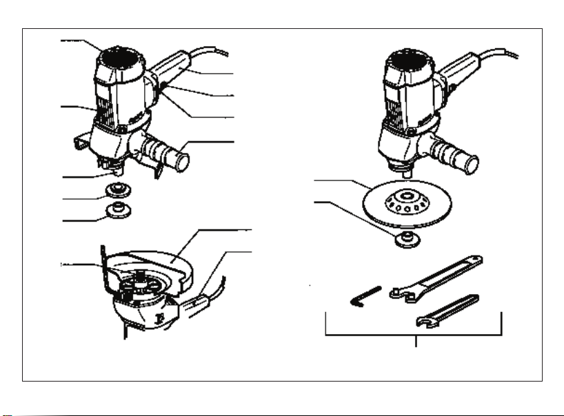
SMONTAGGIO E SOSTITUZIONE DEI DISCHI ABRASIVI
Procedere inversamente a quanto descritto nei capitoli:
- MONTAGGIO DELLA MOLA ABRASIVA
- MONTAGGIO DEL PLATORELLO-PORTADISCO ABRASIVO.
Curare sempre il perfetto serraggio degli utensili onde evitare
infortuni anche gravi.
Non sono ammessi altri attrezzi per il serraggio/disserraggio.
UTENSILI DI LAVORO AMMESSI
- Dischi fibrati da 178 mm;
- mole abrasive con agglomerante organico e struttura fibrosa di
rinforzo con diametro massimo di 178 mm.
Non usare assolutamente utensili non conformi alle presenti
specifiche, o con diametro superiore al consentito, senza la
cuffia di protezione.
MANUTENZIONE
Tutte le operazioni vanno eseguite a spina disinserita.
A fine lavoro, od in caso di necessità, spolverare con getto di aria
compressa il corpo macchina prestando particolare attenzione
alla pulizia delle feritoie di ventilazione del motore.
Non sono ammessi altri interventi da parte dell'utente.
Per la manutenzione e la periodica pulizia delle parti interne, come
spazzole, cuscinetti, ingranaggi etc. o altre necessità rivolgersi ai
Centri di Assistenza autorizzati.
SICUREZZA ELETTRICA - BASSA TENSIONE
Le prove/verifiche sono state eseguite in accordo alle norme:
EN 60745-1 sicurezza degli utensili elettrici a motore portatili
EN 60745-2-3 norme particolari per smerigliatrici.
SCHERMATURA CONTRO I RADIODISTURBI
Le macchine sono conformi agli effetti della prevenzione ed
eliminazione dei radiodisturbi misurati secondo le norme
EN55014-1+ EN55014-2; EN61000-3-2+EN61000-3-3.
FORMAZIONE DI RUMORE / VALORE MEDIO DELL'ACCELERAZIONE
Il livello equivalente di rumorosità/vibrazione sono secondo le norme
EN 60745-1
GARANZIA
Tutte le macchine costruite dalla RUPES Spa sono garantite per
12 mesi dalla data di acquisto contro difetti di materiale e di fab-
bricazione. Le macchine devono essere utilizzate esclusivamente
con accessori e ricambi originali RUPES si declina ogni respon-
sabilità per danni o incidenti provocati dall’inosservanza della
presente norma che causa anche il decadimento della garanzia.
La garanzia decade qualora non vengano rispettate le prescrizio-
ni del presente libretto o qualora venga fatto uso improprio della
macchina. Decade altresì se la macchina viene smontata o ma-
nomessa o se vi sono evidenti danni derivanti da cattiva cura del-
la stessa.
La garanzia è subordinata alla compilazione del tagliando ri-
portato sull’ultima pagina di copertina del presente libretto
d'istruzioni. In caso di accertato malfunzionamento la macchina,
accompagnata dal certificato di garanzia, dovrà essere conse-
gnata o spedita franco di porto, non smontata e nell'imballo ori-
ginale, al fabbricante o ad un Centro di Assistenza autorizzato ri-
portato nell'elenco allegato al presente libretto. In ogni caso la ga-
ranzia non dà diritto alla sostituzione della macchina. La RUPES
Spa si riserva di apportare qualsiasi modifica alle caratteristiche
tecniche o estetiche dei propri prodotti senza preavviso. Non si as-
sume nessuna responsabilità per eventuali errori di stampa. Il
presente stampato annulla e sostituisce i precedenti.
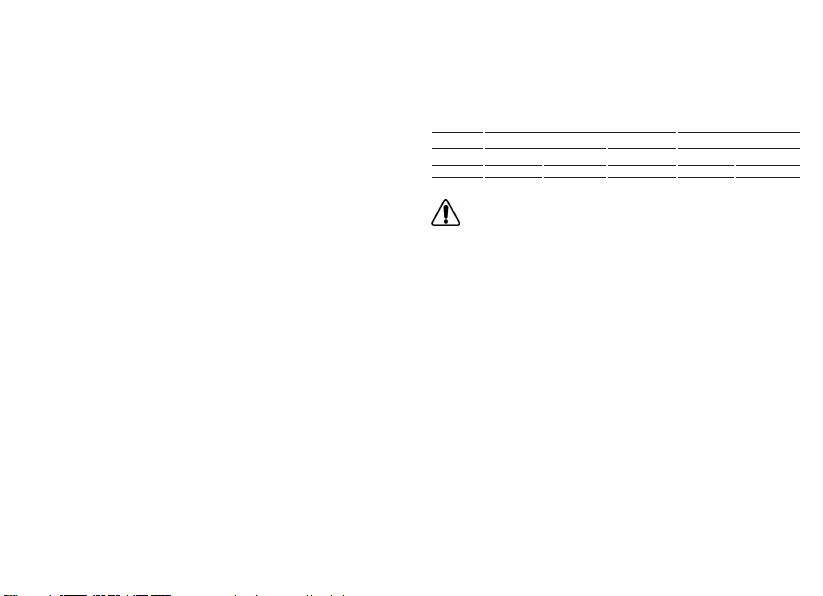
Livello di Pressione acustica / Potenza sonora Livello di vibrazioni su 3 assi
LPA LWA Incertezza ah Incertezza
dB(A) m/s2
SM43N 85 96 3 2,5 0,5
Attenzione! i valori di misura indicati sono validi solo per utensili nuovi.
Nell’impiego quotidiano i valori di rumore e vibrazione cambiano.

7
TARGHETTA DI IDENTIFICAZIONE DELLA MACCHINA
POSIZIONAMENTO E SIGNIFICATO DEI DATI
1. Tipo della macchina.
2. Tensione nominale di lavoro in Volt (V).
3. Frequenza di lavoro in Hertz (Hz).
4. Corrente assorbita espressa in Ampere (A). Accertarsi che la linea elettrica cui viene al-
lacciata la macchina possa agevolmente sopportare almeno la corrente indicata.
5. Potenza assorbita espressa in Watt (W).
6. Numero di matricola o di serie della macchina.
7. Dati tecnici della macchina.
8. Numero di giri/min.
9. Il doppio quadrato indica che la macchina è in doppio isolamento e quindi non necessi-
ta di messa a terra tramite il cordone di alimentazione.
10. Leggere tutte queste istruzioni prima di azionare il presente prodotto.
11. Dispositivi di protezione individuale.
12. Il prodotto, in ottemperanza alla Direttiva Europea 2002/96/CE (RAEE) +
2003/108/CE e alla sua attuazione nel diritto nazionale, quando giunge a fine vita, non
deve essere disperso nell’ambiente o gettato tra i rifiuti domestici, ma deve esse smal-
tito presso i centri di raccolta differenziata autorizzati (contattare le autorità locali com-
petenti per conoscere dove smaltire il prodotto secondo le norme di legge). Il corretto
smaltimento del prodotto contribuisce alla tutela della salute e alla salvaguardia del-
l’ambiente. Lo smaltimento abusivo del prodotto comporta sanzioni a carico dei tra-
sgressori.
Dichiariamo sotto la nostra responsabilità che l’utensile elettrico a
motore portatile, al quale fa riferimento il presente manuale, è
conforme ai Requsiti Essenziali delle Direttive:
2006/42/CE Macchine
2006/95/CE Bassa Tensione
2004/108/CE Compatibilità elettromagnetica
2011/65/CE RoHS
Le prove/verifiche sono eseguite in accordo alle seguenti Normative:
EN 60745-1: 2010 + A11: 2010
EN 60745-2-3: 2011
EN 55014-1: 2006 + A1: 2009 + A2: 2011
EN 55014-2: 1997 + A1: 2001 + A2: 2008
EN 61000-3-2: 2006 + A1: 2009 + A2: 2009
EN 61000-3-3: 2008
EN 62233: 2008
Vermezzo (MI), 20/03/2014
IL PRESIDENTE
G. Valentini
S.p.A
DICHIARAZIONE DI CONFORMITÀ
Fascicolo tecnico presso:
RUPES S.p.A.
Via Marconi, 3A
20080 VERMEZZO (Mi) - Italy

8
TECHNICAL DATA ENGLISH
TYPE
PROTECTION CLASS
ABSORBED POWER
ROTATION RPM
WHEEL/ABRASIVE DISC PAD DIAMETER mm
WEIGHT Kg
SM43N
II
1.100 W
4.200
178
4,2
GENERAL WARNINGS
All instructions concerning safety and the prevention of industrial accidents can be
found in file SAFETY INSTRUCTIONS, that forms integral part of this
documentation. This INSTRUCTION MANUAL only contains additional information
that specifically explain how to use the machine.
SPECIFIC USE
This tool is designed to be used as grinder. Refer to all the safety warnings,
instructions, illustrations and specifications supplied with the tool. Failure to follow
all the instructions provided below may result in electric shocks, fires and/or serious
injuries.
Theuse of this tool for smoothing, metal brushing and polishing operations is not
recommended. Its use for applications other than those for which it has been designed
may lead to hazardous situations and cause injuries to people.
Do not use accessories that are not specifically designed for the intended use of
the tool or that have not been recommended by the manufacturer. The fact that an
accessory can be fixed to the tool does not imply that it can be used safely.
The rated speed of accessories must be at least equivalent to the maximum speed
of the tool. If operated at a greater speed than the rated one, accessories may break
and cause the ejection of chips.
The external diameter and thickness of accessories must be appropriate to
guarantee the protection and safety of the tool. Accessories with incorrect dimensions
cannot be adequately protected or controlled.
The configuration of the cutting/grinding wheels or any other accessory must
perfectly adapt to the tool spindle. Accessories with holes that cannot be aligned with
the fitting components on the tools will cause unbalance, excessive vibrations and may
be difficult to control.
Do not use an accessory if damaged. Before use, inspect all the accessories, like
the abrasive cutting/grinding wheels, in order to verify that they are not cracked or
splintered. If the tool or accessory has fallen, verify that they are not damaged and,
if necessary, replace it with a new one. After inspecting or installing an accessory,
move to a safe distance with any other person present and operate the tool at
maximum speed without load for one minute. Damaged accessories generally break
during this test period.
8
The values shown are based on a nominal voltage of 230V/50Hz. In the case of voltages and frequencies of different power values may vary. Re-
fer to the label technical specifications to the nominal values of the tool.

PARTS OF THE TOOL
1 - Identification plate
2 - ON/OFF switch
3 - Switch locking button
4 - Handle
5 - Protective shield
6 - Spindle
7 - Cylindrical ring nut
8 - Grinding wheel lock nut
9 - Motor ventilation slots
10 - Auxiliary handle
11 - Abrasive disk backing pad
12 - Abrasive disc conical lock nut
13 - Wrenchs (17 mm spanner and pin spanner)
STARTING UP
Before starting-up the tool, ensure that:
- the packaging is complete and does not show signs of having
been damaged during storage or transport;
- the tool is complete; check that the number and type of com-
ponents comply with that reported in this instruction booklet;
- the power supply and socket outlet can support the load repor-
ted in the table and that indicated on the tool identification plate
reproduced and explained on page 11.
ASSEMBLING THE TOOL
Fit the protective shield in its housing on the body of the tool and
tighten the collar using the using the socket head screws sup-
plied.
The shield must be mounted around the handle.
Tighten the auxiliary handle (10); it can be positioned either on the
left or right of the tool body.
FITTING ABRASIVE WHEEL
GRINDER
- Insert the cylindrical ring nut (7) on the spindle (6);
- fit the grinding abrasive wheel on the spindle;
- screw on the grinding wheel lock nut (8) and tighten it using the
pin wrench, preventing the spindle from moving using the 17
mm spanner.
FITTING ABRASIVE DISC PAD
SANDER
- Insert the backing pad (11) on the spindle (6);
- mount the abrasive disc;
- screw on the conical ring nut (12) and tighten it using the pin
wrench, preventing the spindle from moving using the 17 mm
spanner.
BEFORE STARTING THE TOOL
Ensure that:
- the power supply conforms with the characteristics of the tool;
- the power supply cable and plug are in perfect condition;
- the ON/OFF switch works properly by following the instructions
written in the “Tool start-up” chapter, though with the power
supply disconnected;
- all the parts of the tool have been assembled correctly and are
not damaged;
- the ventilation slots are not obstructed.
STARTING AND STOPPING
- Start: press the locking button (3) on the upper section of the handle,
then the switch lever (2). To lock the spindle shaft in order to be able to
carry out a continuous machining, press the switch lever (2), then the
locking lever (3) and hold it down while releasing the switch lever (2),
so that is firmly maintained in position.
- Stop: release the switch lever or, if this is blocked, push the lever in or-
der to release the locking button.
9

10
TEST RUN
Start the tool and check that there is no vibration or dismatching
movement of the abrasive wheel or abrasive disc pad.
Otherwise, switch off immediately and eliminate the cause.
DISMOUNTING AND REPLACING ABRASIVE DISCS
Follow the reverse procedure to that described in the chapters:
- FITTING ABRASIVE WHEEL
- FITTING ABRASIVE DISC PAD.
Always ensure that the tools are perfectly tightened in order
to prevent serious injury.
Tools other than those mentioned must not be used for
slackening for tightening purposes.
USABLE WORKING TOOLS
- 178 mm fibred discs;
- abrasive wheels with an organic agglomerate and fibre reinfor-
cing structure of maximum diameter 178 mm.
Never use tools that do not conform to this specification or
those having a Greater diameter that allowed, without the pro-
tective shield.
MAINTENANCE
All maintenance operations are carried out with the power supply
disconnected.
At the end of each work session, or when required, remove
any dust from the body of the tool using a jet of compressed
air, paying particular attention to the motor ventilation slots.
No other maintenance operations may be undertaken by the
user.
Maintenance and cleaning of the inner parts, like brushes, ball
bearings, gears etc. or others, must be carried out only by an
authorised customer-service workshop.
ELECTRIC SAFETY - LOW TENSION
The tests have been carried out in accordance with the standard:
EN 60745-1 safety of hand-held electric motor operated tools
EN 60745-2-3 particular requirements for grinders.
RADIO SUPPRESSION
The tools are suppressed in accordance for the prevention and
elimination of radio disturbances measured in accordance with
standard: EN55014-1+EN55014-2; EN61000-3-2+EN61000-3-3.
NOISE / MEAN ACCELERATION VALUE
The noise level produced and mean quadratic acceleration value are
measured in according with standard:
EN 60745-1
GUARANTEE
All tools manufactured by RUPES Spa are guaranteed for 12
months from the date of purchase against fabrication and ma-
terial defects.
All tools must be used only with RUPES original accessories and
spare parts: we refuse all responsibility for damages or accidents
caused by non-observance of this rule which will also cause the
termination of the guarantee.
The guarantee will no longer be valid if the instructions contained
in this booklet are not followed, if the tool is used for purposes
other than that for which it is intended, if it is dismantled, interfe-
red with in any way or damaged due to neglect.
The guarantee will be made valid by filling-in the form on the
inside back cover of this instruction booklet.
If the tool is found to be defective or malfunctions, it should be
returned carriage free in one piece in its original packing together
with the guarantee certificate to the manufacturer or to one of the
Assistance Centres listed in the appendix to this booklet.
The guarantee does not automatically imply replacement of the tool.
RUPES Spa reserves the right to make any technical or design
modification to its products without prior notice.
The manufacturer is not liable for any print errors. This document
voids and replaces previous ones.
Sound pressure level / Sound power level 3 axis vibration level
LPA LWA Uncertainty ahUncertainty
dB(A) m/s2
SM43N 85 96 3 2,5 0,5
Danger! The indicate measurements refer to new power tools. Daily
usa causes the noise and vibration values to change.

11
We declare on our responsability that the hand-held motor operated tool, which is mentio-
ned in the present operating manual, is in comformity with the Essential Requirements of Sa-
fety of the following Directives:
2006/42/CE Machinery
2006/95/CE Low Tension
2004/108/CE Electromagnetic Compatibility
2011/65/CE RoHS
The tests have been carried out in accordance with following Standards:
EN 60745-1: 2010 + A11: 2010
EN 60745-2-3: 2011
EN 55014-1: 2006 + A1: 2009 + A2: 2011
EN 55014-2: 1997 + A1: 2001 + A2: 2008
EN 61000-3-2: 2006 + A1: 2009 + A2: 2009
EN 61000-3-3: 2008
EN 62233: 2008
Vermezzo (MI), 20/03/2014
CONFORMITY DECLARATION
TOOL IDENTIFICATION PLATE
POSITION AND MEANING OF INFORMATION
1. Type of tool.
2. Nominal working voltage in Volts (V).
3. Working frequency in Hertz (Hz).
4. Absorbed current in Amperes (A). Ensure that the power supply to which the tool is
connected can easily tolerate the indicated current as a minimum.
5. Absorbed power expressed in Watts (W).
6. Tool code or serial number.
7. Technical data of the tool.
8. Maximum rpm
9. The double square indicates that the tool is doubly insulated and therefore does not re-
quire earthing through the power supply cable.
10. Read all these instructions before operating this product and save these instruc-
tions.
11. Personal safety devices.
12. At the end of its useful life, the product, pursuant to European Directive 2002/96/CE
(RAEE) + 2003/108/CE and its implementation in national law, must not be released in-
to the environment or thrown away as domestic waste, but must be disposed of at au-
thorised recycling centres (contact the relevant local authorities for a list of places where
the product may be disposed of according to the law).Disposing of the product cor-
rectly contributes to protecting human health and safeguarding the environment. Any il-
legitimate disposal of the product will be punishable by law. Technical file at:
RUPES S.p.A.
Via Marconi, 3A
20080 VERMEZZO (Mi) - Italy
IL PRESIDENTE
G. Valentini
S.p.A

12
CARACTERISTIQUES TECHNIQUES FRANCAIS
TYPE
CLASSE DE PROTECTION
PUISSANCE ABSORBEE
TOURS/min
DIAMETRE MEULE/PORTE DISQUE ABRASIF
MASSE Kg
SM43N
II
1.100 W
4.200
178
4,2
12
RECOMMANDATIONS GENERALES
Les instructions sur la sécurité et la prévention des accidents se trouvent sur le fasci-
cule « INDICATIONS SUR LA SÉCURITÉ » qui fait partie intégrante de cette documen-
tation. Le présent MODE D’EMPLOI ne donne que des informations supplémentaires
strictement liées à l’usage spécifique de outil.
UTILISATION CONFORME
Cet outil est prévu pour fonctionner en tant que meuleuse. Lisez toutes les consignes
de sécurité, les instructions, les illustrations et les spécifications fournies avec l’outil.
Le non-respect des instructions ci-après peut donner lieu à un choc électrique, un incendie
et/ou un accident grave.
Il est déconseillé d’effectuer des opérations de ponçage, brossage métallique ou po-
lissage avec cet outil. Les opérations pour lesquelles cet outil n’est pas prévu peuvent pro-
voquer un danger et causer des blessures aux personnes.
N’utilisez pas d’accessoires n’ayant pas été spécialement réalisés pour l’utilisation
prévue ou conseillés par le fabricant. Le simple fait que l’accessoire puisse être fixé sur vo-
tre outil ne garantit pas un fonctionnement en toute sécurité.
La vitesse nominale de l’accessoire doit être au moins égale à la vitesse maximale in-
diquée sur l'outil. Les accessoires fonctionnant à une vitesse supérieure à la vitesse nomi-
nale peuvent se briser et être projetés en l’air.
Le diamètre extérieur et l’épaisseur de votre accessoire doivent être adaptés aux ca-
ractéristiques de capacité du protecteur de votre outil. Il est impossible de protéger ou
de contrôler de façon appropriée les accessoires présentant des dimensions non correctes.
La taille des meules ou de tout autre accessoire doit être adaptée à la broche de l’outil.
Les accessoires dont le perçage ne correspond pas exactement aux éléments de montage
de l’outil sont en déséquilibre, vibrent excessivement et peuvent entraîner une perte de con-
trôle.
N’utilisez pas d’accessoires endommagés. Avant toute utilisation, examinez les acces-
soires tels que les meules abrasives, pour vérifier l’éventuelle présence d’ébréchures
ou de fissures. En cas de chute de l’outil ou de l’accessoire, vérifiez la présence de
dommages ou remplacez l’accessoire. Après avoir examiné et installé un accessoire,
placez-vous, ainsi que les personnes présentes, à une certaine distance de l’accessoi-
re en rotation et faites fonctionner l’outil électrique à sa vitesse maximale à vide pen-
dant une minute. En général, les accessoires endommagés se cassent au cours de cet
d’essai.
Les valeurs indiquées sont basées sur une tension nominale de 230V/50Hz. Dans le cas des tensions et des fréquences de différentes valeurs
de la puissance peut varier. Reportez-vous aux spécifications techniques d'étiquettes pour les valeurs nominales de l'outil.

13
PARTIES DE LA MACHINE
1 - étiquette d'identification
2 - interrupteur de mise en marche - arrêt
3 - bouton-poussoir de blocage interrupteur
4 - poignée
5 - coiffe de protection
6 - arbre mandrin
7 - collier cylindrique
8 - collier cylindrique de fixation de la meule
9 - fentes pour ventilation moteur
10 - poignée auxiliaire
11 - plateau porte-disque abrasif
12 - collier conique de fixation du disque abrasif
13 - cléfs de service (17 mm á echelons)
MISE EN SERVICE
Avant de mettre la machine en service, s'assurer que:
- l'emballage est intégre et qu'il ne montre aucun signe d'endom-
magements dus au transport et au stockage;
- la machine est complète; s'assurer que le nombre et la nature
des composants sont conformes aux indications contenues
dans le présent livret d'instructions;
- la source d'énergie et les prises de courant à disposition peu-
vent supporter la charge indiquée dans le tableau et sur la pla-
quette d'identification de la machine, dont le fac-similé et les ex-
plications relatives sont fournis page 15.
MONTAGE DE LA MACHINE
Monter la coiffe de protection dans le siège prévu à cet effet sur le
corps de la machine et serrer le collier à l'aide de la clé à six pans
fournie avec la machine.
La coiffe doit être montée au niveau de la poignée.
Visser la poignée auxiliaire (10); elle peut être mise à droite ou à
gauche du corps de la machine.
MONTAGE DE LA MEULE ABRASIF
FONCTION PONCEUSE
- Introduire le collier cylindrique (7) sur l'arbre mandrin (6);
- introduire la meule abrasif sur l'arbre mandrin;
- visser le collier de fixation de la meule (8) et serrer à l'aide de la
clé à tétons en immobilisant l'arbre mandrin à l'aide de la clé de
17 mm.
MONTAGE DU PORTE DISQUE ABRASIF
FONCTION MACHINE A RODER
- Mettre le plateau (11) sur l'arbre mandrin (6);
- placer le disque abrasif;
- visser le collier conique (12) et serrer à l'aide de la clé à tétons en
immobilisant l'arbre mandrin à l'aide de la clé de 17 mm.
AVANT LA MISE EN SERVICE
S'assurer que:
- la source d'énergie est conforme aux caractéristiques de la
machine;
- le câble d'alimentation et la fiche relative sont en parfait état;
- l'interrupteur de mise en marche/arrêt est efficace en effectuant
les manoeuvres prévues au chapitre "mise en service", en agis-
sant cependant lorsque la fiche est débranchée;
- tous les composants de la machine sont montés correctement
et ne présentent pas de signes d'endommagement;
- les fentes de ventilation ne sont pas bouchées.
MISE EN MARCHE ET ARRET
- Démarrage: appuyer d’abord sur la touche de verrouillage (3) située à
l’arrière de la poignée puis sur le levier de l’interrupteur (2). Si l’on sou-
haite le verrouillage pour un travail continu, appuyer sur le levier de l’in-
terrupteur (2) puis appuyer sur la touche de verrouillage (3) et la main-
tenir appuyée pendant que l’on relâche le levier de l’interrupteur (2) de
façon à ce que celui-ci reste verrouillé.
- Arrêt: relâcher le levier de l’interrupteur ou, s’il devait être verrouillé, pousser
sur le levier de façon à provoquer le relâchement de la touche de verrouilla-
ge.

14
FONCTIONNEMENT D'ESSAI
Mettre la machine en marche et s'assurer qu'il n'y a pas de vibrations
ou de décentrages de la meule abrasif ou du porte disque abrasif.
Dans le cas contraire, débrancher immédiatement et éliminer
les anomalies.
DEMONTAGE ET REMPLACEMENT DES DISQUES ABRASIFS
Procéder de la façon inverse de ce qui est décrit aux chapitres:
- MONTAGE DE LA MEULE ABRASIF
- MONTAGE DU PORTE DISQUE ABRASIF.
Veiller à ce que les outils soient toujours parfaitement bien
serrés afin d'éviter des accidents qui pourraient être graves.
Aucun autre outil n'est admis pour le serrage/desserrage.
OUTILS DE TRAVAIL ADMIS
- Disques fibreux de 178 mm;
- meules abrasives à agglomérant organique et structure fibreuse
de renfort diamètre maxi 178 mm.
Ne jamais utiliser d’outils non conformes aux presentes
specifications ou ayant un diamètre superieur au diamètre
autorisé sans la coiffe de protection.
ENTRETIEN
Toutes les opérations doivent être effectuées la fiche étant débranchée.
A la fin du travail et en cas de nécessité, dépoussiérer le corps de
la machine à l'aide d'un jet d'air comprimé en accordant une atten-
tion particulière au nettoyage des fentes de ventilation du moteur.
Aucune autre intervention de l'utilisateur n'est admise.
Tous les travaux d’entretien et les travaux de polissage des
piéces internes, comme les brosses, coussinet, engrenages etc.,
doivent être effecuès par un atelier de réparation autorisè.
SECURITE ELECTRIQUE - BASSE TENSION
Les proves/verifies out eté executés en accord a les normes:
EN 60745-1 securité des outils électrique a moteur portatives
EN 60745-2-3 règles particuliers puor meuleuses.
PROTECTION CONTRE LES PARASITES RADIO
Les machines sont conformes à les effets de la prévention et des
parasites radio mesures en accord a les normes EN55014-1+
EN55014-2; EN61000-3-2+EN61000-3-3.
FORMATION DU BRUIT / VALEUR MOYENNE DE L'ACCELERATION
Le niveau équivalent de la pression sonore (niveau de bruit) e la va-
leur quadratique moyenne de l'accèlérationest est mesurés confor-
mément aux normes:
EN 60745-1
GARANTIE
Toutes les machines construites par la Société RUPES Spa sont
garanties pendant 12 mois à compter de la date d’achat contre
les défauts matériau et de fabrication.
Les machines ne doivent être utilisées qu'avec les pièces déta-
chées et les accessoires originaux RUPES: nous déclinons toute
responsabilité en cas d'accidents ou de dégâts matériels provo-
qués par le non-respect de cette norme, qui entraînera en outre
l'annulation de la garantie.
La garantie prend fin en cas de non-respect des prescriptions du
présent livret ou en cas d’utilisation impropre de la machine. Elle
prend fin également si la machine est démontée ou modifiée ou
en cas de dommages évidents dérivant d’un mauvais entretien.
La garantie est subordonnée au remplissage du coupon qui
se trouve à la dernière page de couverture du présent livret
d’instructions.
En cas de mauvais fonctionnement, la machine, accompagnée
de son certificat de garantie, devra être remise ou envoyée en
port payé, non démontée et dans son emballage d’origine, au fa-
bricant ou à un Centre d’Assistance agrée indiqué sur la liste an-
nexée au présent livret.
La garantie ne donne pas en aucun cas
droit au remplacement de la machine.
RUPES Spa se réserve le droit de modifier sans préavis les
caractéristiques techniques ou esthétiques des ses produits.
Nous déclinons toute responsabilité quant aux erreurs d'impres-
sion éventuelles. Ce document annule et remplace tous les pré-
cédents.
Niveau de pression acoustique / Niveau de puissance acoustique Niveau des vibration selon 3 axies
LPA LWA Incertitude ahIncertitude
dB(A) m/s2
SM43N 85 96 3 2,5 0,5
Attention! Les valeurs de mesure indiquées s’appliquent aux appareils neufs.
Pendant le mise en ceuvre quotidienne, les valeurs de bruit et de vibrations
varient.

15
Nous déclarons sous notre responsabilité que l’outil électrique à moteur portable, auquel
se réfère le présent manuel, est conforme aux Conditions Essentielles des Directives :
2006/42/CE Machines
2006/95/CE Basse Tension
2004/108/CE Compatibilité électrimagnétique
2011/65/CE RoHS
Les proves/vérifiés out été exécutés en accord a les vigueurs Régles Harmonisés Euro-
péennes
Basse Tension:
EN 60745-1: 2010 + A11: 2010
EN 60745-2-3: 2011
EN 55014-1: 2006 + A1: 2009 + A2: 2011
EN 55014-2: 1997 + A1: 2001 + A2: 2008
EN 61000-3-2: 2006 + A1: 2009 + A2: 2009
EN 61000-3-3: 2008
EN 62233: 2008
Vermezzo (MI), 20/03/2014
DÉCLARATION DE CONFORMITÉ
PLAQUETTE D’IDENTIFICATION DE LA MACHINE
EMPLACEMENT ET SIGNIFICATION DES DONNEES
1. Type de la machine.
2. Tension nominale de travail en Volts (V).
3. Fréquence de travail en Hertz (Hz).
4. Courant absorbé exprimé en Ampéres (A). S’assurer que la ligne électrique à laquelle
la machine est branchée pourra aisément supporter au moins le courant indiqué.
5. Puissance absorbée exprimée en Watts (W).
6. Numéro d’immatriculation ou de série de la machine.
7. Caractéristiques techniques de la machine.
8. Nombre de tours/min.
9. Le double carré indique que la machine est à double isolement et que par consé-
quent, la mise à la terre par le cordon d’alimentation n’est pas nècessaire.
10. Lire toutes ces instructions avant de mettre en marche le présent produit.
11. Dispositifs de protection individuels.
12. Conformément à la Directive européenne 2002/96/CE (RAEE) + 2003/108/CE et
à sa mise en application dans la législation nationale, les vieux produits ne doivent être
jetés ni dans la nature ni avec les ordures ménagères mais être remis à un centre de
collecte sélective autorisé (adressez-vous à votre mairie pour savoir où vous débarras-
ser du produit conformément à la loi).L’élimination correcte du produit contribue à la
protection de la santé et de l’environnement. En n’éliminant pas le produit conformé-
ment à la loi en vigueur vous vous exposez à des sanctions. Dossier technique auprès de :
RUPES S.p.A.
Via Marconi, 3A
20080 VERMEZZO (Mi) - Italy
IL PRESIDENTE
G. Valentini
S.p.A

16
TECHNISCHE DATEN DEUTSCH
ALLGEMEINE HINWEISE
Die Sicherheits- und Unfallverhütungsvorschriften sind im beiliegenden Heft HINWEI-
SE ZUR SICHERHEIT enthalten, das integrierender Teil dieser Dokumentation ist. Die-
se GEBRAUCHSANLEITUNG enthält daher nur Zusatzinformationen, welche den spe-
zifischen Einsatz des Geräts betreffen.
BESTIMMNGSGEMÄßE VERWENDUNG
Dieses Werkzeug ist für den Einsatz als Schleifmaschine bestimmt. Alle
Sicherheitshinweise, die Anweisungen, die Abbildungen und die technischen Daten
beachten, die mit diesem Werkzeug geliefert werden. Die mangelnde Beachtung aller
unten aufgeführten Anweisungen kann zu elektrischen Schlägen, Brand und/oder schwe-
ren Unfällen führen.
Von Vorgängen des Schleifens, metallischen Bürstens und Polierens mit diesem
Werkzeug wird abgeraten. Vorgänge, für die der Einsatz des Werkzeugs nicht vorgesehen
ist, können eine Gefahr darstellen und Personenschäden verursachen.
Kein Zubehör verwenden, das nicht ausdrücklich für den vorgesehenen Gebrauch
hergestellt oder vom Hersteller empfohlen wurde. Die bloße Tatsache, dass das Zube-
hör auf Ihrem Werkzeug angebracht werden kann, garantiert keine Funktionsweise unter
völlig sicheren Bedingungen.
Die Nenngeschwindigkeit des Zubehörs muss mindestens der auf dem Werkzeug
angegebenen Höchstgeschwindigkeit entsprechen. Zubehör, dass bei einer
Geschwindigkeit über der Nenngeschwindigkeit verwendet wird, kann brechen und in die
Luft geschleudert werden.
Der Außendurchmesser und die Stärke Ihres Zubehörs müssen sich für den
Schutzgrad der Sicherheitsvorrichtung Ihres Werkzeugs eignen. Zubehör mit nicht
korrekten Größen kann nicht angemessen geschützt oder kontrolliert werden.
Die Beschaffenheit der Schleifscheiben oder jeglichen anderen Zubehörs muss sich
korrekt an das Spannfutter des Werkzeugs anpassen. Zubehör mit Bohrungen der
Welle, die nicht mit den Montageelementen auf dem Werkzeug übereinstimmen, bleiben
nicht im Gleichgewicht, vibrieren zu stark und können zu einem Kontrollverlust führen.
Verwenden Sie kein beschädigtes Zubehör. Vor jedem Einsatz das Zubehör wie die
Schleifscheiben auf eventuelle Splitterungen oder Risse untersuchen. Ist das
Werkzeug oder das Zubehör heruntergefallen, auf eventuelle Schäden untersuchen
oder nicht beschädigtes Zubehör installieren. Nachdem ein Zubehörartikel untersucht
und installiert wurde, begeben Sie sich gemeinsam mit den anwesenden Personen in
einen Sicherheitsabstand von dem rotierenden Zubehörartikel und lassen Sie das
Werkzeug bei Höchstgeschwindigkeit eine Minute lang leer laufen. Beschädigtes
Zubehör bricht im Allgemeinen während dieses Probezeitraums.
TYP
SCHUTZKLASSE
LEISTUNGSAUFNAHME
UMDREHUNGEN/MINUTE
Ø TRENNSCHEIBE/SCHLEIFTELLER mm
GEWICHT kg
SM43N
II
1.100 W
4.200
178
4,2
16
Die dargestellten Werte basieren auf einer Nennspannung von 230V/50Hz basiert. Im Falle von Spannungen und Frequenzen von verschiede-
nen Leistungswerten kann variieren. Beziehen sich auf die technischen Spezifikationen Label auf die Nennwerte des Werkzeugs.

17
BAUTEILE DER MASCHINE
1 - Schild mit Geräte-Kenndaten
2 - EIN/AUS-Schalter
3 - Schalter-Sperrtaste
4 - Handgriff
5 - Schutzkappe
6 - Spindelwelle
7 - Zylindrische Nutmutter
8 - Spannmutter f. Schleifteller
9 - Motor-Lüftungsschlitze
10 - Seitenhandgriff
11 - Spannmutter Schleifteller
12 - Kegelförmige Nutmutter zur Befestigung der Trennscheibe
13 - Service-Schlüssel (17 mm und Spannmutterschlüssel)
INBETRIEBNAHME
Vor einer Inbetriebnahme des Gerätes sollten Sie sicherstellen:
- daß die Verpackung unversehrt ist und keine Beschädigungen
durch Transport bzw. Lagerung aufweist;
- daß das Gerät vollständig ist, also Anzahl und Art der Geräte-
komponenten mit den Angaben in dieser Gebrauchsanleitung
überein stimmen;
- daß Stromnetz und Steckdosen für die in der Tabelle bzw. auf
dem Geräteschild (vgl. Abbildung u. Beschreibung des Gerate-
schilds auf Seite 19) genannte Stromlast ausgelegt sind.
ZUSAMMENBAU DER MASCHINE
Die Schutzkappe auf die entsprechende Aufnahme am Gerätege-
häuse aufsetzen und den Kragen mit dem beigestellten Inbussch-
lüssel festziehen.
Die Schutzkappe muß über dem Handgriff montiert werden.
Den seitehandgriff einschrauben (10); er kann wahlweise links
bzw. rechts an das Gehäuse angesetzt werden
BEFESTIGUNG VON TRENNSCHEIBE
EINSATZ ALS SCHLEIFMASCHINE
- Die zylindrische Nutmutter (7) auf die Spindelwelle (6) schieben;
- den Trennscheibe auf die Spindelwelle aufsetzen;
- die Spannmutter des Schleiftellers (8) aufschrauben und mit
dem Stirnlochschlüssel festdrehen. Dabei die Spindelwelle mit
dem 17 mm-Schlüssel kontern.
BEFESTIGUNG DER SCHLEIFTELLER
EINSATZ ALS HONMASCHINE
- Die Scheibe (11) auf die Spindelwelle (6) schieben;
- die Schleifteller positionieren;
- die kegelförmige Nutmutter (12) aufschrauben und mit dem
Stirnlochschlüssel festdrehen. Dabei die Spindelwelle mit dem
17 mm-Schlüssel kontern.
VOR DER INBETRIEBNAHME
Folgende Punkte sicherstellen:
- Das Stromnetz muß den Gerätekenndaten entsprechen;
- Anschlußkabel und -stecker müssen in einwandfreiem Zustand
sein;
- der EIN/AUS-Schalter muß einwandfrei funktionieren. Zur Über-
prüfung die in Kapitel "Inbetriebnahme" beschriebenen Schaltstel-
lungen - allerdings bei gezogenem Netzstecker - ausprobieren;
- Sämtliche Gerätekomponenten müssen ordnungsgemäß mon-
tiert sein und dürfen keine Anzeichen von Beschädigung zeige;
- die Lüftungsschlitze müssen frei sein.
EINSCHALTEN UND AUSSCHALTEN
- Start: Zuerst die Sperrtaste (3) oben am Griff drücken und anschließend
den Hebel des Schalters (2) betätigen. Falls die Unterbrechung des Be-
triebs gewünscht wird, den Hebel des Schalters (2) niederdrücken,
anschließend die Sperrtaste (3) gedrückt halten und gleichzeitig Hebel
des Schalters (2) loslassen, so dass dieser blockiert bleibt.
- Stoppen: Den Hebel des Schalters loslassen oder, sofern er blockiert
ist, darauf drücken, sodass die Sperrtaste freigegeben wird.

18
TESTLAUF
Schalten Sie das Gerät ein und stellen Sie sicher, daß der Schleifteller
bzw. die Trennscheibe nicht vibriert oder unrund läuft.
Andernfalls das Gerät sofort ausschalten und die Störung beheben.
ABNEHMEN UND ERSETZEN DER SCHEIBEN
Die im Abschnitt genannten Schritte in umgekehrter Reihenfolge au-
sführen. Sorgen Sie dafür, daß die Scheiben immer absolut sicher
festgezogen sind.
- BEFESTIGUNG VON TRENNSCHEIBE
- BEFESTIGUNG DER SCHLEIFTELLER.
Nachlässigkeit kann hierbei zu schwersten Verletzungen führen.
Die Verwendung sonstiger Werkzeuge zum Festziehen/Lösen ist
nicht zulässsig.
ZULÄSSIGE WERKZEUGE
- Fiberscheiben mit 178 mm Ø;
- Trennscheiben aus organischem Verbundmaterial mit Fiberverstär-
kung, max. Durchmesser 178 mm.
Verwenden sie auf Keinen fall Ohne Schutzhaube Werkzeuge, die
nicht dieser Spezifikation Entsprechen oder deren Durchmesser
den Zulässigen Durchmesser Überschreitet.
PFLEGE DES GERÄTES
Sämtliche Eingriffe bei gezogenem Netzstecker ausführen.
Das Gerät nach der Arbeit sowie bei Bedarf mit Druckluft von Staub
befreien. Besonders darauf achten, daß die Lüftungsschlitze des Mo-
tors sauber sind.
Sonstige Eingriffe durch den Geräteanwender sind nicht zulässig.
Für die Wartung und die periodische Reinigung von den inneren
Teilen z. B: Bürsten, Lagern, Zahnrädern usw. oder andere Bedürfnis-
se wenden Sie sich bitte an einer autorisierten Kundendienststelle an.
ELEKTRISCHE SICHERHEIT - NIEDERSPANNUNG
Die Tests wurden nach den Anforderungen der zur Zeit gültigen
Normen ausgeführt:
EN 60745-1 sicherheit für tragbare elektrisch betriebe Maschinen
EN 60745-2-3 besondere Anforderungen für Winkelschleifer.
FUNKENTSTÖRUNG
Die Geräte erfüllen die Vorschriften der EG-Richtlinie 89/336 zur Vor-
beugung und Beseitigung von Funkstörungen Messung nach Norm
EN55014-1+EN55014-2; EN61000-3-2+EN61000-3-3.
SCHALLPEGEL / MITTLERE BESCHLEUNIGUNG
Der Schalldruckpegel (Geräuschentwicklung) und die mittlere quadrati-
sche Beschleunigungder Maschine, gemessen gemäß:
EN 60745-1
GARANTIE
Für alle von ihr hergestellten Geräte leistet die Fa. RUPES Spa Ge-
währ im von Mangeln, die innerhalb von 12 Monaten ab dem Kauf-
datum aufgrund Material-oder Fabrikationsfehlern auftreten. Die Ma-
schinen dürfen ausschließlich mit Originalzubehör und Originaler-
satzteilen von RUPES betrieben werden: Das Unternehmen haftet
nicht für Unfälle oder Schäden, die auf die Nichtbeachtung dieser Be-
stimmung zurückzuführen sind, die außerdem zum unverzüglichen
Verfall der Garantie führt. Der Garantieanspruch entfällt bei unsach-
gemäßem Gebrauch des Gerätes oder der Nichteinhaltung dieser
Gebrauchasanleitung. Er entfällt ebenfalls, wenn das Gerät demon-
tiert bzw. umgerüstet wurde oder sichtbare Schäden infolge mangel-
hafter Pflege aufweist. Die Inansprunchnahme der Garantielei-
stung ist nur möglich, wenn der Abschnitt auf der vorletzten
Umschlagseite dieser Gebrauchsanleitung ausgefüllt ist. Im Fall
einer nachweislichen Funktiosstörung muß das Gerät dem Hersteller
komplett montiert, originalverpackt und mit beiliegender Garantiekar-
te fracht und portofrei übergeben bzw. zugesendet werden. Die
Übergabe an ein autorisiertes Kundendienstzentrum (siehe beilie-
gendes Verzeichnis) ist ebenfalls möglich. In keinem Fall leitet sich
aus dem Garantieanspruch ein Rechtsanspruch auf die Ersetzung
des Gerätes ab. Die Fa. RUPES SpA behält sich das Recht vor, ohne
Vorankündigung technische und ästhetische Änderungen an ihren
Produkten vorzunehmen. Das Unternehmen haftet nicht für eventuel-
le Druckfehler. Vorliegendes Dokument annulliert und ersetzt alle frü-
heren Veröffentlichungen.
Schalldruckpegel / Schalleistungspegel 3-Achsen Vibrationspegel
LPA LWA
Messunsicherheit
ah
Messunsicherheit
dB(A) m/s2
SM43N 85 96 3 2,5 0,5
Achtung! Di angegebenen Messwerte gelten für neue Geräte. Im täglichen
Einsatz verändern sich Geräusch-und chwingungswerte.

19
KENNDATENSCHILD DES GERÄTES
ANORDNUNG UND BEDEUTUNG DER ANGABEN
1. Gerätetyp.
2. Nenn-Anschlußspannung in Volt (V).
3. Frequenz in Hertz (Hz).
4. Stromaufnahme in Ampere (A).Es ist sicherzustellen, daß die Stromleitung, an die das
Gerät angeschlossen werden soll, mindestens diese Strombelastung problemlos aus-
hält.
5. Leistungsaufnahme in Watt (W).
6. Geräte- oder Seriennummer.
7. Technische Gerätedaten.
8. Drehzahl in Umdrehungen/Min.
9. Das doppelte Quadrat zeigt an, daß das Gerät zweifach schutzisoliert ist und daher kei-
ne Erdung über das Anschlußkabel erforderlich ist.
10. Lesen Sie diese Hinweise aufmerksam durch, bevor Sie das vorliegende Produkt
in Betrieb nehmen.
11. Persönliche Schutz-Ausrüstung.
12. Das Produkt darf entsprechend der Europäischen Richtlinie 2002/96/CE (RAEE)
+ 2003/108/CE und deren Umsetzung in der nationalen Gesetzgebung am Ende sei-
ner Lebensdauer nicht weggeworfen oder im Hausmüll entsorgt werden, sondern
muss bei den autorisierten Zentren zur Abfalltrennung abgegeben werden (wenden
Sie sich an die zuständigen Behörden vor Ort, um zu erfahren, wo das Produkt nach
den gesetzlichen Bestimmungen zu entsorgen ist). Die korrekte Entsorgung des Pro-
dukts trägt zum Schutz der Gesundheit und der Umwelt bei. Die missbräuchliche Ent-
sorgung des Produkts zieht Sanktionen zu Lasten des Verursachers nach sich.
Wir bestätigen in unserer Verantwortung das die Handgehaltenen Motorwerkzeuge, die in
diesem Betriebshandbuch beschrieben werden, ist in Übereinstimmung mit den wesentli-
chen Bestimmungen für die Sicherheit der folgenden Direktiven:
2006/42/CE Maschinenrichtlinie
2006/95/CE Niederspannung
2004/108/CE Elektromagnetische Verträglichkeit
2011/65/CE RoHS
Die Tests wurden ausgeführt nach den Anforderungen der zur Zeit gültigen europäischen
Harmonisierungsregeln Niederspannung:
EN 60745-1: 2010 + A11: 2010
EN 60745-2-3: 2011
EN 55014-1: 2006 + A1: 2009 + A2: 2011
EN 55014-2: 1997 + A1: 2001 + A2: 2008
EN 61000-3-2: 2006 + A1: 2009 + A2: 2009
EN 61000-3-3: 2008
EN 62233: 2008
Vermezzo (MI), 20/03/2014
KONFORMITÄTSERKLÄRUNG
Technische Unterlagen bei:
RUPES S.p.A.
Via Marconi, 3A
20080 VERMEZZO (Mi) - Italy
IL PRESIDENTE
G. Valentini
S.p.A

20
DATOS TECNICOS ESPAÑOL
ADVERTENCIAS GENERALES
Las instrucciones para la seguridad y la prevención de los accidentes se en-
cuentran en el folleto INDICACIONES PARA LA SEGURIDAD que constituye
parte integrante de esta documentación. Este MANUAL DE INSTRUCCIONES
de uso contiene solamente información adicional estrechamente relacionada
con el uso específico de la máquina.
USO CONFORME A LO DETERMINADO
Esta herramienta está destinada a funcionar como esmeriladora. Leer todas
las advertencias de seguridad, las instrucciones, las ilustraciones y las espe-
cificaciones suministradas con esta herramienta. El incumplimiento de las in-
strucciones puede causar descargas eléctricas, incendios y/o accidentes graves.
Se recomienda no ejecutar con esta herramienta operaciones de lijado, ace-
pilladura metálica ni pulido. El empleo de la herramienta eléctrica en operacio-
nes para las que no está diseñada puede provocar peligros y daños a las perso-
nas.
No utilizar accesorios no realizados específicamente para el uso previsto o no
aconsejados por el productor. El hecho de que el accesorio se pueda fijar en la
herramienta no garantiza un funcionamiento totalmente seguro.
La velocidad nominal del accesorio debe ser al menos igual a la velocidad má-
xima indicada en la herramienta. Los accesorios que se hagan funcionar a una
velocidad superior a la nominal pueden romperse y saltar por el aire.
El diámetro exterior y el espesor de su accesorio deben responder a las ca-
racterísticas de capacidad de la protección de seguridad de su herramienta
eléctrica. Los accesorios de dimensiones no correctas no se pueden proteger y
controlar adecuadamente.
La conformación de las muelas o de cualquier otro accesorio debe adaptarse
correctamente al mandril de la herramienta. Los accesorios cuyos orificios en el
eje no correspondan con los elementos de montaje en la herramienta no perma-
necerán en equilibrio, vibrarán excesivamente y podrán provocar una pérdida de
control.
No utilizar accesorios dañados. Antes del uso, examinar los accesorios, como
las muelas abrasivas, para asegurarse de que no presentan mellas o grietas.
Si la herramienta o el accesorio han sufrido una caída, verificar si hay daños
o instalar un accesorio no dañado. Una vez examinado e instalado un acce-
sorio, colocarse a una distancia de seguridad del accesorio giratorio, al igual
que las demás personas presentes, y poner en funcionamiento la herramien-
ta a la velocidad máxima en vacío durante un minuto. Los accesorios dañados
generalmente se rompen durante el período de prueba.
.
TIPO
CLASE DE PROTECCION
POTENCIA ABSORBIDA
REVOLUCIONES POR MINUTO
DIAMETRO MUELA/PLATILLO PORTADISCO ABRASIVO mm
MASA kg
SM43N
II
1.100 W
4.200
178
4,2
20
Los valores mostrados se basan en una tensión nominal de 230V/50Hz. En el caso de tensiones y frecuencias de los valores de potencia dife-
rentes puede variar. Consulte las especificaciones de la etiqueta técnica a los valores nominales de la herramienta.
Other manuals for SM43N
1
Table of contents
Languages:
Other Rupes Grinder manuals