Rupes LHR15ES Manual

RUPES S.p.A.
Via Marconi, 3A
20080 VERMEZZO (Mi) - Italy
Tel. 02/946941
Fax 02/94941040
Uff. Vendite e assistenza clienti
Tel. 02/94694312
web: http://www.rupes.com
COD. ART. 9.2460 -FEBBRAIO 2013
LHR 15ES - LHR21ES
Lucidatrice
Polisher
Lustreuse
Poliermaschine
Pulidora
Haakse poetsmachine
Полировальная машина
ISTRUZIONI ORIGINALI PER L'USO E LA MANUTENZIONE
ORIGINAL OPERATING AND MAINTENANCE INSTRUCTIONS
NOTICE ORIGINAL D'EMPLOI ET D'ENTRETIEN
ORIGINAL-BEDIENUNGS-UND WARTUNGSANLEITUNG
INSTRUCCIONES ORIGINAL DE USO Y MANUTENCION
AANWIJZINGEN VOOR HET GEBRUIK EN HET ONDERHOUD
ORIGINEEL
ИНСТРУКЦИЯ ПО ЭКСПЛУАТАЦИИ И ОБСЛУЖИВАНИЮ
1
ОРИГИНАЛЬНЫЙ
4
8
12
16
20
24
28
Leggere tutte queste istruzioni prima di azionare il
presente prodotto
.
Indicazioni importanti per la sicurezza dell’utilizzatore
Lesen Sie zuerst die folgenden Anweisung bevor Sie das
Gerät bedienen.
Wichtige Sicherheitsangaben
Antes de accionar este producto es necesario leer todas
estas instrucciones
Indicaciones importantes para la seguridad del usuario
Lees de volgende instructie voor u het product gebruikt
Belangrijke veiligheids instructies
Следует прочитать все эти инструкции прежде, чем
приводить овку.
Важные указания для безопасности пользователя
Lire toutes ces instructions avant d’actionner
le présent produit.
Indications importantes pour la sécurité de l’utilisateur
Read the following instruction first before operate
the product
Important safety indications
ISTRUZIONI ORIGINALI PER L'USO
E LA MANUTENZIONE
ORIGINAL OPERATING AND
MAINTENANCE INSTRUCTIONS
NOTICE ORIGINAL D'EMPLOI ET
D'ENTRETIEN
ORIGINAL-BEDIENUNGS-UND
WARTUNGSANLEITUNG
INSTRUCCIONES ORIGINAL DE
USO Y MANUTENCION
AANWIJZINGEN VOOR HET GE-
BRUIK EN HET ONDERHOUD ORI-
GINEEL
ИНСТРУКЦИЯ ПО
ЭКСПЛУАТАЦИИ И
ОБСЛУЖИВАНИЮ1 ГИНАЛЬНЫЙ
op LHR 15ES - LHR 21ES COPERTINA FEBBRAIO 2013:Layout 1 01/03/2013 9.32 Pagina 1

4
DATI TECNICI ITALIANO 4
34
21 5
4
5
MODELLO LHR 15ES LHR21ES
CLASSE DI PROTEZIONE II II
TENSIONE DI LAVORO 230 V - 50 Hz 230 V - 50 Hz
CORRENTE ASSORBITA 2 A 2 A
POTENZA ASSORBITA 500 W 500 W
REGOLAZIONE ELETTRONICA DELLA VELOCITÀ SI SI
GIRI/min 2000 ÷ 5000 2000 ÷ 4000
FILETTATURA DELL’ALBERO MANDRINO M8 M8
Ø PLATORELLO mm 125 150
DIAMETRO MAX DEL TAMPONE mm 150 180
TIPO PLATORELLO VELCRO VELCRO
MASSA Kg 2,2 2,25
AVVERTENZE GENERALI
Le istruzioni per la sicurezza e la prevenzione degli infortuni sono
riportate nel fascicolo “INDICAZIONI PER LA SICUREZZA” che
costituisce parte integrante della presente documentazione, Il pre-
sente MANUALE D’ISTRUZIONI per l’uso riporta solamente le
informazioni aggiuntive strettamente correlate all’uso specifico della
macchina.
UTILIZZO CONFORME AGLI SCOPI PREVISTI
Questo utensile è destinato a funzionare come lucidatrice. Leggere
tutti gli avvertimenti di sicurezza, le istruzioni, le illustrazioni e le
specifiche forniti con questo utensile. Il mancato rispetto di tutte le istru-
zioni sotto riportate può causare una scossa elettrica, un incendio e/o un
incidente grave.
Le operazioni di molatura, levigatura, spazzolatura metallica o di
taglio non sono consigliate con questo utensile. Le operazioni per le
quali non è previsto l’utensile possono provocare un pericolo e causare
danni alle persone.
Non utilizzare accessori non specificatamente realizzati per l’uso pre-
visto o non consigliati dal produttore. Il semplice fatto che l’accessorio
possa essere fissato al vostro utensile non garantisce un funzionamento
in tutta sicurezza.
La velocità nominale dell’accessorio deve essere almeno pari alla
velocità massima indicata sull’utensile. Gli accessori fatti funzionare a
una velocità superiore a quella nominale possono rompersi ed essere
proiettati in aria.
Il diametro esterno e lo spessore del vostro accessorio devono
essere adatti alle caratteristiche di capacità del vostro utensile. Gli
accessori che hanno dimensioni non corrette non possono essere protetti
o controllati adeguatamente.
La conformazione degli accessori deve adattarsi correttamente al
mandrino dell’utensile. Gli accessori dotati di fori dell’albero che non
corrispondono agli elementi di montaggio sull’utensile non rimarranno in
equilibrio, vibreranno eccessivamente e potranno provocare una perdita
di controllo.
Non usare un accessorio danneggiato. Se l’utensile o l’accessorio ha
subito una caduta, esaminare i danni eventuali o installare un
accessorio non danneggiato. Dopo aver esaminato e installato un
accessorio, mettetevi, insieme alle persone presenti, a una distanza
di sicurezza dall’accessorio rotante e fate funzionare l’utensile alla
velocità massima a vuoto per un minuto. Gli accessori danneggiati si
romperanno in genere in questo periodo di prova.
1
10
4
8
7
3
2
13
5
6
9
11
1
10
4
8
7
3
2
13
5
6
9
11
LHR 15ES
LHR 21ES
op LHR 15ES - LHR 21ES COPERTINA FEBBRAIO 2013:Layout 1 01/03/2013 9.32 Pagina 2

5
AVVERTENZE DI SICUREZZA SPECIFICHE PER LE
OPERAZIONI DI LUCIDATURA
Non permettere ad alcuna parte allentata della cuffia
dell’accessorio di lucidatura ne alle stringhe di fissaggio di girare
liberamente. Mettere in sicurezza o tagliare ogni fili di fissaggio
allentato. I fili di fissaggio allentati e in rotazione possono attorci-
gliarsi sulle vostre dita oppure impigliarsi sul pezzo in lavorazio-
ne.
PARTI DELLA MACCHINA
1 - Etichetta di identificazione
2 - Interruttore di inserimento-disinserimento
3 - Regolazione elettronica della velocità
4 - Vite di fissaggio
5 - Chiave di servizio
6 - Impugnatura ausiliaria (optional)
7 - Impugnatura
8 - Tampone di lucidatura (optional)
9 - Viti fissaggio dell’ impugnatura
10 - Platorello velcro
11 - Feritoie per ventilazione motore
12 - Protezione ausiliaria (optional)
13 - Pulsante di bloccaggio interruttore
MESSA IN FUNZIONE
Prima di mettere in funzione la macchina accertarsi che:
- l’imballo sia integro e non mostri segni di danneggiamento do-
vuti a trasporto e magazzinaggio;
- la macchina sia completa; controllare che numero e natura dei
componenti siano conformi a quanto riportato sul presente libretto;
-la fonte di energia e le prese di corrente a disposizione possano
sopportare il carico indicato in tabella e riportato sulla targhetta
di identificazione della macchina il cui facsimile, con spiegazio-
ni, è riportato a pag. 7.
MONTAGGIO DELLA MACCHINA
Posizionare l’impugnatura (7) sulla scatola ingranaggi in modo
che i fori siano allineati con quelli della scatola ingranaggi. Avvita-
re quindi le viti (9).
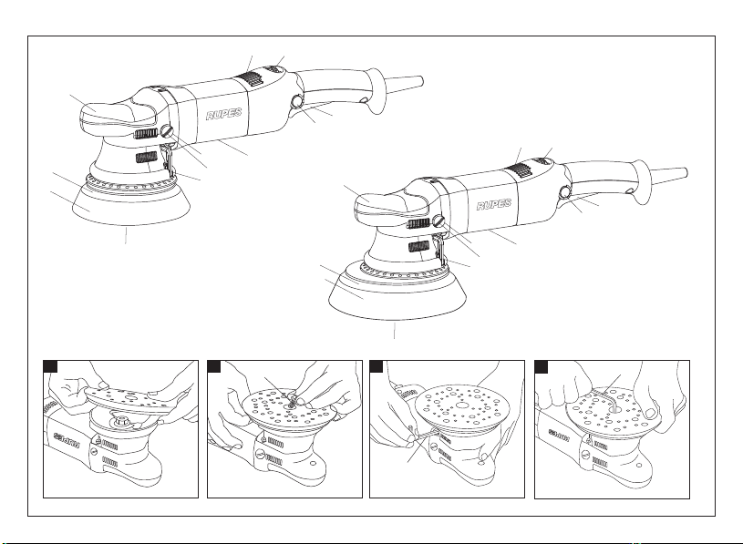
MONTAGGIO DEL PLATORELLO
1. Appoggiare il platorello (10) con la vite al centro (4) (fig. 1);
2. ruotare leggermente il platorello (10) fino al corretto
posizionamento (fig. 2);
3. serrate la vite con la chiave in dotazione (5) (fig. 3).
Non serrate la vite del platorello se questo è in posizione scor-
retta (fig. 4);
4. per lo smontaggio operare in senso inverso
5. Attaccare il tampone al platorello velcro
MONTAGGIO DEL TAMPONE DI LUCIDATURA
Fare aderire mediante pressione il tampone di lucidatura al
platorello.
PRIMA DELLA MESSA IN SERVIZIO
Accertarsi che:
- la fonte di energia sia conforme alle caratteristiche della macchina;
- cavo di alimentazione e relativa spina siano in perfetto stato;
- l'interruttore di inserimento/disinserimento sia efficiente operan-
do, però, a spina disinserita;
- tutti i componenti della macchina siano montati correttamente e
non presentino segni di danneggiamento;
- le feritoie di ventilazione non siano ostruite.
AVVIAMENTO E FERMATA
- Avviamento: spingere la leva dell'interuttore (2) verso il corpo
macchina; qualora se ne desideri il bloccaggio in posizione "inse-
rito", spingere contemporaneamente il pulsante (13) mantenen-
dolo premuto, mentre si rilascia la leva (2) in modo che la stessa
resti bloccata.
- Fermata: rilasciare la leva dell'interruttore o, qualora sia bloccato,
spingere sulla leva in modo da provocare il rilascio del pulsante di
blocco.
FUNZIONAMENTO DI PROVA
Avviare la macchina e controllare che non siano presenti vibrazio-
ni o scentrature del piattello portatampone.
In caso contrario spegnere la macchina immediatamente e
provvedere ad eliminare le anomalie.
REGOLAZIONE ELETTRONICA DEL NUMERO DI GIRI
La regolazione del numero di giri si ottiene manovrando opportu-
namente la rotella (3) posta nella parte superiore della macchina.
La scelta della velocità va fatta in funzione delle caratteristiche dei
tamponi e del materiale da lavorare.

6
SOSTITUZIONE DEL TAMPONE DI LUCIDATURA
Asportare a strappo il tampone usato e applicare il nuovo
premendolo sul platorello.
ACCESSORI
LHR 21ES: Tamponi Ø 180 mm per platorelli Ø 150 mm.
MANUTENZIONE
Tutte le operazioni vanno eseguite a spina disinserita.
A fine lavoro, od in caso di necessità, spolverare con getto di aria
compressa il corpo macchina prestando particolare attenzione
alla pulizia delle feritoie di ventilazione del motore.
Non sono ammessi altri interventi da parte dell'utente.
Per la manutenzione e la periodica pulizia delle parti interne, come
spazzole, cuscinetti, ingranaggi, etc. o altre necessità rivolgersi ai
Centri di Assistenza autorizzati.
SICUREZZA ELETTRICA - BASSA TENSIONE
Le prove/verifiche sono state eseguite in accordo alle norme:
EN 60745-1 sicurezza degli utensili elettrici a motore portatili
EN 60745-2-4 norme particolari per lucidatrici diverse da tipo
a disco.
SCHERMATURA CONTRO I RADIODISTURBI
Le macchine sono conformi agli effetti della prevenzione ed elimina-
zione dei radiodisturbi misurati secondo le norme EN55014-1+
EN55014-2; EN61000-3-2
Valori di emissione di rumorosità / vibrazioni secondo norma:
+EN61000-3-3.
FORMAZIONE DI RUMORE /
EN 60745-1
VALORE MEDIO DELL'ACCELERAZIONE
GARANZIA
Tutte le macchine costruite dalla RUPES Spa sono garantite per
12 mesi dalla data di acquisto contro difetti di materiale e di fabbri-
cazione.
Le macchine devono essere utilizzate esclusivamente con acces-
sori e ricambi originali RUPES: si declina ogni responsabilità per
danni o incidenti provocati dall’inosservanza della presente nor-
ma che causa anche il decadimento della garanzia.
La garanzia decade qualora non vengano rispettate le prescrizio-
ni del presente libretto o qualora venga fatto uso improprio della
macchina. Decade altresì se la macchina viene smontata o mano-
messa o se vi sono evidenti danni derivanti da cattiva cura della
stessa.
La garanzia è subordinata alla compilazione del tagliando ri-
portato sull’ultima pagina di copertina del presente libretto
d'istruzioni.
In caso di accertato malfunzionamento la macchina, accompa-
gnata dal certificato di garanzia, dovrà essere consegnata o spe-
dita franco di porto, non smontata e nell'imballo originale, al fab-
bricante o ad un Centro di Assistenza autorizzato riportato nell'e-
lenco allegato al presente libretto.
In ogni caso la garanzia non dà diritto alla sostituzione della mac-
china.
La RUPES Spa si riserva di apportare qualsiasi modifica alle carat-
teristiche tecniche o estetiche dei propri prodotti senza preavviso.
Non si assume nessuna responsabilità per eventuali errori di
stampa. Il presente stampato annulla e sostituisce i precedenti.
LHR 15ES: Tamponi Ø 150 mm per platorelli Ø 125 mm.
Livello di Pressione acustica / Potenza sonora Livello di vibrazioni su 3 assi
LPA LWA Incer tezza ahIncer tezza
2
dB(A) m/s
LHR 15ES 77
77
88
88
32,7 1,5
32,7 1,7
LHR 21ES
Attenzione! i valori di misura indicati sono validi solo per utensili nuovi.
Nell'impiego quotidiano i valori di rumore e vibrazione cambiano.

7
TARGHETTA DI IDENTIFICAZIONE DELLA MACCHINA
POSIZIONAMENTO E SIGNIFICATO DEI DATI
1. Tipo della macchina.
2. Tensione nominale di lavoro in Volt (V).
3. Frequenza di lavoro in Hertz (Hz).
4. Corrente assorbita espressa in Ampere (A). Accertarsi che la linea
elettrica cui viene allacciata la macchina possa agevolmente sop-
portare almeno la corrente indicata.
5. Potenza assorbita espressa in Watt (W).
6. Numero di matricola o di serie della macchina.
7. Dati tecnici della macchina.
8. Numero di giri/min.
9. Il doppio quadrato indica che la macchina è in doppio isolamento
e quindi non necessita di messa a terra tramite il cordone di ali-
mentazione.
10. Leggere tutte queste istruzioni prima di azionare il presente
prodotto.
11. Dispositivi di protezione individuale.
12. Il prodotto, in ottemperanza alla Direttiva Europea
2002/96/CE (RAEE) + 2003/108/CE e alla sua attuazione nel dirit-
to nazionale, quando giunge a fine vita, non deve essere disperso
nell’ambiente o gettato tra i rifiuti domestici, ma deve esse smalti-
to presso i centri di raccolta differenziata autorizzati (contattare le
autorità locali competenti per conoscere dove smaltire il prodotto
secondo le norme di legge). Il corretto smaltimento del prodotto
contribuisce alla tutela della salute e alla salvaguardia dell’am-
biente. Lo smaltimento abusivo del prodotto comporta sanzioni a
carico dei trasgressori.
Dichiariamo sotto la nostra responsabilità che l’utensile elettrico a
motore portatile, al quale fa riferimento il presente manuale, è
conforme ai Requsiti Essenziali delle Direttive:
2006/42/CE Macchine
2006/95/CE Bassa Tensione
2004/108/CE
2011/65/CE
Compatibilità elettromagnetica
RoHS
Le prove/verifiche sono eseguite in accordo alle seguenti Normative:
IL PRESIDENTE
G. Valentini
S.p.A
DICHIARAZIONE DI CONFORMITÀ
EN 60745-1: 2010
EN60745-2-4:2009 + A11:2011
EN 55014-1: 2006 + A1: 2009 + A2: 2011
EN 55014-2: 1997 + A1: 2001 + A2: 2008
EN 61000-3-2: 2006 + A1: 2001 + A2: 2009
EN61000-3-3: 2008
EN 62233: 2008
Vermezzo (MI), 21/12/2012

8
TECHNICAL DATA ENGLISH
TYPE LHR15ES LHR21ES
PROTECTION CLASS II II
OPERATING VOLTAGE 230 V - 50 Hz 230 V - 50 Hz
ABSORBED CURRENT 2 A 2 A
ABSORBED POWER 500W 500W
ELECTRONIC SPEED CONTROL YES YES
ROTATION RPM 2000÷5000 2000÷4000
PAD FIXING THREAD M8 M8
PAD DIAMETER mm 125 150
BUFFER PAD DIAMETER MAX mm 150 180
PAD TYPE VELCRO FACED VELCRO FACED
WEIGHT Kg 2,2 2,25
8
GENERAL WARNINGS
The safety and accident prevention instructions are reported in
the “SAFETY INSTRUCTION” booklet which forms an integral part
of these documents. This OPERATING INSTRUCTIONS MANUAL
indicates the additional information required specifically for use
of the tool.
CORRECT USAGE
This tool is designed to be used as a polisher. Read all the
warnings, instructions, indications provided on drawings and
specifications supplied with this tool. Failure to comply with all the
instructions provided below may cause electrical shocks, fires and/or
serious injuries.
This tool is not intended to be used for smoothing, metal
brushing and cutting operations. The use of this tool for unintended
applications may cause hazards and injuries to people.
The tool must be used with accessories that have been
specifically designed or recommended by the manufacturer. The
fixing of the accessory to the tool does not guarantee a safe
operation.
The rated speed of the accessories must be at least equivalent to
the maximum speed specified on the tool. Using the accessories
at speeds above the rated one, may cause them to break or be
projected into the air.
The external diameter and thickness of the accessories must
match the specifications of the tool. Accessories with incorrect
dimensions cannot be adequately protected or controlled.
The configuration of accessories must match the tool. The use of
accessories that cannot be perfectly fitted on the tool may result in
imbalance, excessive vibrations and in the impossibility of controlling
the tool.
Do not use damaged accessories. Before use, inspect all the
accessories. Inspect the supporting pads and verify there are no
cracks, tears or excessive wear. If the tool or accessory has
fallen, verify that it is not damaged or install a new accessory.
After inspecting or installing an accessory, test the operation of
the tool at maximum speed and without load for one minute,
keeping at a safety distance. If the accessories are damaged, they
will break during this test.

9
SAFETY WARNINGS APPLICABLE TO POLISHING OPERATIONS
Verify that no loosened part of the polishing tool shroud or
the locking ties can rotate freely. Safely position or cut all the
loosened fixing wires. Loosened or revolving fixing wires may
twist around the operator’s fingers or get caught by the work
piece being machined.
PARTS OF THE TOOL
1 - Identification plate
2 - ON/OFF switch
3 - Electronic speed control
4 - Disc pad fixing screw
5 - Disc pad Allen wrench
6 - Auxiliary handle (not supplied)
7 - Handle
8 - Buffer pad (not supplied)
9 - Handle fixing screws
10 - Velcro faced disc pad
11 - Motor ventilation slots
12 - Auxiliary protection (optional)
13 - Switch locking button
STARTING UP
Before starting-up the tool ensure that:
- the packaging is complete and does not show signs of having
been damaged during storage or transport;
- the tool is complete; check that the number and type of
components comply with that reported in this instruction
booklet;
- the power supply and socket outlet can support the load
reported in the table and that indicated on the tool identification
plate reproduced and explained on page 11.
ASSEMBLING THE TOOL
- Position the handle (7) on the gearbox such that the holes for
mounting the screws (9) are aligned with those on the gearbox.
MOUNTING THE DISC PAD
1. Place the disc pad (10) with the screw (4) in the centre (fig. 1);
2. slightly turn the disc pad (10) until it is fixed to the screw as in
fig 2;
3. tighten the screw using the supplied Allen wrench (5) (fig. 4).
Do not tighten the backing plate screw if it is in the wrong
position;
4. to remove, follow the same procedure in reverse order;
5. Assembre the buffer pad on the velcro surface of the pad.
ASSEMBLING THE BUFFER PAD
Press the buffer pad to attach it to the disc pad.
BEFORE STARTING THE TOOL
Ensure that:
- the power supply conforms with the characteristics of the tool;
- the power supply cable and plug are in perfect condition;
- the ON/OFF switch works properly though with the power
supply disconnected;
- all the parts of the tool have been assembled in the proper
manner and that there are no signs of damage;
- the ventilation slots are not obstructed.
STARTING AND STOPPING
- Starting: push the lever of the switch (2) fowards the body of the
tool; if the tool is to be locked in the ON position, press button
(13) at the same time and keep it pressed while releasing lever
(2), thus locking the switch.
- Stopping: release the lever of the switch or, if locked in position,
push the lever to release the lock button.
TEST RUN
Start the tool and check that there are no unusual vibration, or no
dismatching of the buffer pad.
Otherwise switch-off the tool immediately and eliminate the
fault.
ELECTRONIC RPM REGULATION
The rpm can be adjusted by rotating the wheel (3). The choice of
speed depends on the characteristics of the buffers and the ma-
terial to be worked.

10
REPLACING THE BUFFER PAD
Pull the used pad off and apply the new one, pressing it onto
the disc pad.
ACCESSORIES
LHR 21ES: Buffer pads Ø 180 mm for Ø 150 mm pads.
LHR 15ES: Buffer pads Ø 150 mm for Ø 125 mm pads.
MAINTENANCE
All maintenance operations are carried out with the power supply
disconnected.
At the end of each work session, or when required, remove any
dust from the body of the tool using a jet of compressed air,
paying particular attention to the motor ventilation slots.
No other maintenance operations must be undertaken by the
user.
Maintenance and cleaning of the inner parts, like brushes, ball
bearings, gears etc. or others, must be carried out only by an
autorized customer-service workshop.
ELECTRIC SAFETY - LOW TENSION
The tests have been carried out in accordance with the standard:
EN 60745-1 safety of hand-held electric motor operated tools
EN 60745-2-4 particular requirements for polishers other than
disk type.
RADIO SUPPRESSION
The tools are suppressed in accordance for the prevention and
elimination of radio disturbances measured in accordance with
standard: EN55014-1+EN55014-2; EN61000-3-2+EN61000-3-3.
NOISE / MEAN ACCELERATION VALUE
GUARANTEE
All tools manufactured by RUPES Spa are guaranteed for 12
months from the date of purchase against fabrication and material
defects.
All tools must be used only with RUPES original accessories and
spare parts: we refuse all responsibility for damages or accidents
caused by non-observance of this rule which will also cause the
termination of the guarantee.
The guarantee will no longer be valid if the instructions contained in
this booklet are not followed, if the tool is used for purposes other
than that for which it is intended, if it is dismantled, interfered with in
any way or damaged due to neglect.
The guarantee will be made valid by filling-in the form on the
inside back cover of this instruction booklet.
If the tool is found to be defective or malfunctions, it should be retur-
ned carriage free in one piece in its original packing together with
the guarantee certificate to the manufacturer or to one of the Assi-
stance Centres listed in the appendix to this booklet.
The guarantee does not automatically imply replacement of the tool.
RUPES Spa reserves the right to make any technical or design
modification to its products without prior notice.
The manufacturer is not liable for any print errors. This document
voids and replaces previous ones.
The noise level produced and mean quadratic acceleration value
are measured in according with standard:
EN 60745-1
Sound pressure level / Sound power level 3 axis vibration level
LPA LWA Uncer tainty ahUncer tainty
2
dB(A) m/s
Danger! The indicate measurements refer to new power tools. Daily usa
causes the noise and vibration values to change.
LHR 15ES 77
77
88
88
32,7 1,5
32,7 1,7
LHR 21ES

11
TOOL IDENTIFICATION PLATE
POSITION AND MEANING OF INFORMATION
1. Type of tool.
2. Nominal working voltage in Volts (V).
3. Working frequency in Hertz (Hz).
4. Absorbed current in Amperes (A). Ensure that the power supply to
which the tool is connected can easily tolerate the indicated
current as a minimum.
5. Absorbed power expressed in Watts (W).
6. Tool code or serial number.
7. Technical data of the tool.
8. Maximum rpm
9. The double square indicates that the tool is doubly insulated and
therefore does not require earthing through the power supply
cable.
10. Read all these instructions before operating this product and
save these instructions.
11. Personal safety devices.
12. At the end of its useful life, the product, pursuant to European
Directive 2002/96/CE (RAEE) + 2003/108/CE and its
implementation in national law, must not be released into the
environment or thrown away as domestic waste, but must be
disposed of at authorised recycling centres (contact the relevant
local authorities for a list of places where the product may be
disposed of according to the law).Disposing of the product
correctly contributes to protecting human health and
safeguarding the environment. Any illegitimate disposal of the
product will be punishable by law.
We declare on our responsability that the hand-held motor operated tool,
which is mentioned in the present operating manual, is in comformity with
the Essential Requirements of Safety of the following Directives:
2006/42/CE Machinery
2006/95/CE Low Tension
2004/108/CE
2011/65/CE
Electromagnetic Compatibility
RoHS
The tests have been carried out in accordance with following Standards:
IL PRESIDENTE
G. Valentini
S.p.A
CONFORMITY DECLARATION
EN 60745-1: 2010
EN 55014-1: 2006 + A1: 2009 + A2: 2011
EN 55014-2: 1997 + A1: 2001 + A2: 2008
EN 61000-3-2: 2006 + A1: 2001 + A2: 2009
EN61000-3-3: 2008
EN 62233: 2008
EN60745-2-4:2009 + A11:2011
Vermezzo (MI), 21/12/2012

12
TYPE LHR15ES LHR21ES
CLASSE DE PROTECTION II II II
TENSION DE TRAVAIL
COURANT ABSORBÉE 2 A 2 A
PUISSANCE ABSORBÉE
RÉGLAGE ÉLECTRONIQUE DE LA VITESSE
TOURS/min 2000 ÷5000 2000 ÷4000
OUI
M8
230 V - 50 Hz 230 V - 50 Hz
M8
125 150
150
FIXATION VELCRO FIXATION VELCRO
180
500W
OUI
500W
FILETAGE DE L’ARBRE MANDRIN
DIAMÈTRE MAX DU DISQUE mm
DIAMÈTRE MAX DU TAMPON mm
TYPE PORTE DISQUE
MASSE Kg 2,2 2,25
CARACTÉRISTIQUES TECHNIQUES FRANÇAIS 12
RECOMMANDATIONS GENERALES
Les instructions relatives à la sécurité et à la protection contre les
accidents du travail sont contenues dans le fascicule
"INDICATIONS RELATIVES A LA SECURITE" qui fait partie
intégrante de la présente documentation. Le present NOTICE
D'INSTRUCTIONS relatives à l'utilisation indique uniquement les
informations complémentaires qui sont étroitement linées à
l'utilisation spécifique de la machine.
UTILISATION CONFORME
Cet outil est prévu pour fonctionner en tant que lustreuses. Lire
toutes les prescriptions de sécurité, les instructions, les
illustrations et les spécifications fournies avec cet outil. Le non-
respect de toutes les instructions susmentionnées peut provoquer
une décharge, un incendie et/ou un accident grave.
Il est déconseillé d’effectuer des opérations de ponçage,
brossage métallique ou de coupe avec cet outil. Les opérations
pour lesquelles l’outil n’est pas prévu peuvent provoquer un danger
et causer des blessures aux personnes.
Ne pas utiliser les accessoires qui ne sont pas spécialement
conseillés par le producteur. Le simple fait que l’accessoire puisse
être fixé sur votre outil ne garantit pas un fonctionnement en toute
sécurité.
La vitesse nominale de l’accessoire doit être au moins égale à la
vitesse maximale indiquée sur l'outil. Les accessoires que l’on
utilise à une vitesse supérieure à la vitesse nominale peuvent se
casser et être projetés en l’air.
Le diamètre extérieur et l’épaisseur de votre accessoire doivent
être adaptés aux caractéristiques de capacité de votre outil. Il est
impossible de protéger ou de contrôler de façon appropriée les
accessoires présentant des dimensions non correctes.
La conformation des accessoires doit s’adapter correctement au
mandrin de l’outil. Les accessoires munis de trous de l’arbre qui ne
correspondent pas aux éléments de montage sur l’outil ne resteront
pas en équilibre, ils vibreront excessivement et pourront provoquer
une perte de contrôle.
Ne pas utiliser un accessoire endommagé. Avant toute utilisation,
examiner les accessoires. Si l’outil ou l’accessoire est tombé,
examiner les éventuels dégâts ou installer un accessoire non
endommagé. Après avoir examiné et installé un accessoire,
placez-vous, ainsi que les personnes présentes, à une certaine
distance de securite de l’accessoire tournant et faites fonctionner
l’outil à la vitesse maximale à vide pendant une minute. Les
accessoires endommagés se casseront en général durant cette
période d’essai.

13
CONSIGNES DE SECURITE SPECIFIQUES POUR LES
OPERATIONS DE LUSTRAGE
Ne permettre à aucune partie desserrée de la protection de l'ac-
cessoire de lustrage ni aux lacets de fixation de tourner librement.
Sécuriser ou couper tout fil de fixation desserré. Les fils de fixa-
tion desserrés et en rotation peuvent s'entortiller autour de vos
doigts ou s'entraver sur la pièce travaillée.
PARTIES DE LA MACHINE
1 - Ètiquette d’identification
2 - Interrupteur de mise en marche - arrêt
3 - Réglage électronique de la vitesse
4 - Vis de fixation
5 - Clès de service
6 - Poignée auxiliaire (optional)
7 - Poignée
8 - Tampon de polissage (optional)
9 - Vis de fixation protection de poignée
10 - Plateau velcro
11 - Fentes pour ventilation du moteur
12- Protection auxiliaire (optional)
13 - Bouton de blocage interrupteur
MISE EN SERVICE
Avant de mettre la machine en service, s'assurer que:
- l'emballage est intègre et qu'il ne montre aucun signe
d'endommagements dus au transp ort et au stockage;
- la machine est complète; s'assurer que le nombre et la nature
des composants sont conformes aux indications contenues
dans le présent livret d'instructions;
- la source d'énergie et les prises de courant à disposition
peuvent supporter la charge indiquée dans le tableau et sur la
plaquette d'identification de la machine, dont le fac-similé et les
explications relatives sont fournis page 15.
MONTAGE DE LA MACHINE
Positionner la poignée (7) sur la boîte d’engrenages de manière à
ce que les trous soient alignés avec ceux de la boîte d’engrena-
ges. Visser ensuite les vis (9).
MONTAGE DE LA PLATEAU
1. Poser le plateau de surfaçage (10) avec la vis au centre (4) (fig.
1);
2. faire rouler légèrement le plateau (10) pour le faire adhérer à la
vis, comme en (fig. 2);
3. serrer la vis avec la clé accompagnant le produit (5) (fig. 3).
Ne pas serrer la vis du plateau si celui-ci est en position
incorrecte (fig. 4);
4. Pour démonter, opérer dans le sens inverse
5. Fixer le tampon sur le plateau.
MONTAGE DU TAMPON DE POLISSAGE
Appuyer sur le tampon de polissage pour le faire adhérer sur le
plateau avec velcro.
AVANT LA MISE EN SERVICE
S'assurer que:
- la source d'énergie est conforme aux caractéristiques de la
machine;
- le câble d'alimentation et la fische relative sont en parfait état;
- l'interrupteur de mise en marche/arrêt est efficace en agissant
cependant lorsque la fiche est débranchée;
- tous les composants de la machine sont montés correctement
et ne présentent pas de signes d'endommagement;
- les fentes de ventililation ne sont pas bouchées.
MISE EN MARCHE ET ARRET
- Mise en marche: pousser la levier de l'interrupteur (2) vers le
corps de la machine; pour le bloquer en position "ouvert",
pousser en même temps le bouton (13) et ne pas le relacher
pendant que l'on relache le levier (2) de façon à ce que celle-ci
reste bloquée.
- Arrêt: relacher le levier de l'interrupteur ou, s'il est bloquè,
pousser sur le levier de façon à ce que le bouton de blocage
soit relaché.
FONCTIONNEMENT D'ESSAI
Mettre la machine en marche et s'assurer que le disque abrasif ne
vibre pas ou n'est pas décentré de le plateau porte-tampon.
Dans le cas contraire, débrancher immediatement et éliminer
les anomalies.
RÉGLAGE ÉLECTRONIQUE DU NOMBRE DE TOURS
Le réglage du nombre de tours s’obtient en manoeuvrant de
maniére appropriée le bouton (3) situé sur la partie supérieur de
la machine. Le choix de la vitesse doit être fait en fonction des
caractéristiques de le tampons et du matériau à usiner.

14
REPLACEMENT DU TAMPON DE POLISSAGE
Détacher le tampon usé et mettre en place le nouveau en
l’enfonçant sur le porte-disque.
OUTILS DE TRAVAIL ADMIS
LHR 21ES:Tampons Ø
LHR 15ES: Tampons Ø
180 mm pour plateau Ø 150 mm.
150 mm pour plateau Ø 125 mm.
ENTRETIEN
Toutes le opérations doivent être effectuées à fiche étant débranchée.
A la fin du travail et en cas de nécessité, dépoussiérer le corps de
la machine à l’aide d’un jet d’air comprimé en faisant particulié-
rement attention au nettoyage des fentes de ventilation du moteur.
Aucune autre intervention de l’utilisateur n’est pas admise.
Tous les travaux d’entretien et les travaux de polissage des
piéces internes, comme les brosses, coussinet, engrenages, etc.,
doivent être effecuès par un Atelier de Réparation autorisè.
SECURITE ELECTRIQUE - BASSE TENSION
Les proves/verifies out eté executés en accord a les normes:
EN 60745-1 securité des outils électrique a moteur portatives
EN 60745-2-4 règles particuliers puor lustreuses autres que du
PROTECTION CONTRE LES PARASITES RADIO
Les machines sont conformes à les effets de la prévention et des
parasites radio mesures en accord a les normes EN55014-1+
EN55014-2; EN61000-3-2+EN61000-3-3.
FORMATION DU BRUIT
VALEUR MOYENNE DE L'ACCELERATION
GARANTIE
Toutes les machines construites par la Société RUPES Spa sont
garanties pendant 12 mois à compter de la date d’achat contre
les défauts matériau et de fabrication.
Les machines ne doivent être utilisées qu'avec les pièces déta-
chées et les accessoires originaux RUPES: nous déclinons toute
responsabilité en cas d'accidents ou de dégâts matériels provo-
qués par le non-respect de cette norme, qui entraînera en outre
l'annulation de la garantie.
La garantie prend fin en cas de non-respect des prescriptions du
présent livret ou en cas d’utilisation impropre de la machine. Elle
prend fin également si la machine est démontée ou modifiée ou
en cas de dommages évidents dérivant d’un mauvais entretien.
La garantie est subordonnée au remplissage du coupon qui se
trouve à la dernière page de couverture du présent livret d’instruc-
tions.
En cas de mauvais fonctionnement, la machine, accompagnée de
son certificat de garantie, devra être remise ou envoyée en port
payé, non démontée et dans son emballage d’origine, au fabricant
ou à un Centre d’Assistance agrée indiqué sur la liste annexée au
présent livret.
La garantie ne donne pas en aucun cas droit au remplacement de la
machine.
RUPES Spa se réserve le droit de modifier sans préavis les ca-
ractéristiques techniques ou esthétiques des ses produits.
Nous déclinons toute responsabilité quant aux erreurs d'impres-
sion éventuelles. Ce document annule et remplace tous les
précédents.
Le niveau équivalent de la pression sonore e la valeur quadratique
moyenne de l'accèlératio (niveau de bruit) mesurés conformément
EN 60745-1
Attention! Les valeurs de mesure indiquées s'appliquent aux appareils
neufs. Pendant le mise en ceuvre quotidienne, les valeurs de bruit et de
vibrations varient.
Niveau de pression acoustique / Niveau de puissance acoustique Niveau des vibration selon 3 axies
LPA LWA Incer titude ahIncer titude
2
dB(A) m/s
aux normes
LHR 15ES 77
77
88
88
32,7 1,5
32,7 1,7
LHR 21ES
type à disque.

15
PLAQUETTE D’IDENTIFICATION DE LA MACHINE
EMPLACEMENT ET SIGNIFICATION DES DONNEES
1. Type de la machine.
2. Tension nominale de travail en Volts (V).
3. Fréquence de travail en Hertz (Hz).
4. Courant absorbé exprimé en Ampéres (A). S’assurer que la ligne
électrique à laquelle la machine est branchée pourra aisément
supporter au moins le courant indiqué.
5. Puissance absorbée exprimée en Watts (W).
6. Numéro d’immatriculation ou de série de la machine.
7. Caractéristiques techniques de la machine.
8. Nombre de tours/min.
9. Le double carré indique que la machine est à double isolement et
que par conséquent, la mise à la terre par le cordon d’alimenta-
tion n’est pas nècessaire.
10. Lire toutes ces instructions avant de mettre en marche le
présent produit.
11. Dispositifs de protection individuels.
12. Conformément à la Directive européenne 2002/96/CE
(RAEE) + 1003/108/CE et à sa mise en application dans la législa-
tion nationale, les vieux produits ne doivent être jetés ni dans la
nature ni avec les ordures ménagères mais être remis à un centre
de collecte sélective autorisé (adressez-vous à votre mairie pour
savoir où vous débarrasser du produit conformément à la loi).L’é-
limination correcte du produit contribue à la protection de la santé
et de l’environnement. En n’éliminant pas le produit conformé -
ment à la loi en vigueur vous vous exposez à des sanctions.
Nous déclarons sous notre responsabilité que l’outil électrique à mo-
teur portable, auquel se réfère le présent manuel, est conforme aux
Conditions Essentielles des Directives :
2006/42/CE Machines
2006/95/CE Basse Tension
2004/108/CE
2011/65/CE
Compatibilité électrimagnétique
RoHS
Les proves/vérifiés out été exécutés en accord a les vigueurs Régles
Harmonisés Européennes
Basse Tension:
IL PRESIDENTE
G. Valentini
S.p.A
DÉCLARATION DE CONFORMITÉ
EN 60745-1: 2010
EN 55014-1: 2006 + A1: 2009 + A2: 2011
EN 55014-2: 1997 + A1: 2001 + A2: 2008
EN 61000-3-2: 2006 + A1: 2001 + A2: 2009
EN61000-3-3: 2008
EN 62233: 2008
EN60745-2-4:2009 + A11:2011
Vermezzo (MI), 21/12/2012

16
TYP LHR15ES LHR21ES
SCHUTZKLASSE II II
SPANNUNG 230 V - 50 Hz 230 V - 50 Hz
STROMAUFNAHME 2 A 2 A
LEISTUNGAUFNAHME 500 W 500 W
ELEKTRONISCHE DREHZAHLREGELUNG JA JA
UMDREHUNGEN U/min 2000 ÷5 000 2000 ÷ 4000
WELLENGEWINDE M8 M8
PURCHMESSER SCHLEIFTFELLER 125 150
MAX POLIERSCHWAMM mm 150 180
TYP SCHLEIFTFELLER KLETT SYSTEM KLETT SYSTEM
GEWICHT Kg 2,2 2,25
TECHNISCHE DATEN DEUTSCH 16
ALLGEMEINE HINWEISE
Die Sicherheits-und Unfallverhütungsvorschriften sind im
beiliegenden Heft „HINWEISE ZUR SICHERHEIT" enthalten. Das Heft
ist integrierender Bes tandteil der v orliegenden Dokumen tation;
Diese BEDIENUNGSANLEITUNG enthält daher nur
Zusatzinformationen, welche den spezifischen Einsatz dieses Geräts
betreffen.
BESTIMMNGSGEMÄßE VERWENDUNG
Dieses Werkzeug ist für den Einsatz als Poliermaschine bestimmt.
Alle Sicherheitshinweise, die Anweisungen, die Abbildungen und die
techn isch en Dat en beac hten, di e mit di esem Werkze ug gel ief ert
werden. Die Nichtbeachtung aller unten aufgeführten Anweisungen kann
einen elektrischen Schlag, Brand und/oder schweren Unfall verursachen.
Von Vorgängen des Fe inschleifens, S chleifens, metallischen
Bürstens oder Schneidens wird mit diesem Werkzeug abgeraten. Die
Vorgänge, für die der Einsatz des Werkzeugs nicht vorgesehen ist,
können zu Gefahren führen und Personenschäden verursachen.
Kein nicht spez ifisch für den vorge sehenen Einsatz hergestell tes
oder n icht vom Hers teller empf ohl enes Zu behör ver wenden. Die
bloße Tatsache, dass da s Zubehörteil auf Ihrem Werkzeug be festigt
werden kann, garantiert keinen vollkommen sicheren Betrieb.
Die Nenngeschwindigkeit des Zubehörs muss mindestens der auf
dem Werkzeug angegebenen Höchstgeschwindigkeit entsprechen.
Zubehör, das bei einer höheren Geschwindigkeit als der
Nenngeschwindigkeit betrieben wi rd, kann b rechen und in die Luft
geschleudert werden.
Der Außendurchmesser und die Stärke Ihres Zubehörs müssen sich
für die Charakteristiken Ihres Werkzeugs eignen. Zubehör mit nicht
korrekten Abmessungen kann nicht angemessen geschützt oder
kontrolliert we rden. Die Be schaffenheit des Zubehörs mus s si ch
korrekt an das Spannfutter des Werkzeugs anpassen. Zubehör mit
Bohrungen der Welle, die nicht mit den Montageelementen auf dem
Werkzeug übereinstimmen, bleiben nicht im Gleichgewicht, vibrieren
zu stark und können zu einem Ko ntrollverlust führen. Ke in
beschädigtes Zubehör verwenden. Ist das Werkzeug oder das
Zubehör heruntergefallen, auf eventuelle Schäden untersuchen oder
nicht beschädigtes Zubehör installieren. Nachdem ein
Zubehörartike l untersucht und insta lliert wu rde, begeben Sie sich
gemeinsam mit den anwesenden Pe rsonen in einen
Sicherheitsabstand von dem rotierenden Zubehörartikel und lassen
Sie das Werkzeug bei Höchstgeschwindigkeit eine Minute lang leer
laufen . Beschädigtes Zubehör bricht im Allgemeinen während dieses
Probezeitraums.

17
SPEZIFISCHE SICHERHEITSHINWEISE FÜR DIE POLIERVORGÄNGE
Weder gelösten Teilen der Haube des Polierwerkzeugs noch
den Bindern gestatten, frei zu drehen. Jegliche gelösten Bin-
der sichern oder abschneiden. Die gelösten und rotierenden
Binder können sich um Ihre Finger wickeln oder auf dem
bearbeiteten Teil verfangen.
BAUTEILE DER MASCHINE
1 - Schild mit Geräte-Kenndaten
2 - EIN/AUS-Schalter
3 - Elektronische Drehzahlregelung
4 - Schraube
5 - Service-Schlüssel
6 - Seitlichen Handgriff (optional)
7 - Griff
8 - Polierballens (optional)
9 - Befestigungsschraube des Griffs
10 - Schleiftfeller
11 - Schlitze zur Motorkühlung
12- Zusatzschutz (optional)
13- Schalter-Arretiertaste
INBETRIEBNAHME
Vor einer Inbetriebnahme des Gerätes sollten Sie sicherstellen:
- daß die Verpackung unversehrt ist und keine Beschädigungen
durch Transport bzw. Lagerung aufweist;
- daß das Gerät vollständig ist, also Anzahl und Art der Geräte-
komponenten mit den Angaben in dieser Gebrauchsanleitung
überein stimmen;
- daß Stromnetz und Steckdosen für die in der Tabelle bzw. auf
dem Geräteschild (vgl. Abbildung u. Beschreibung des
Gerateschilds auf Seite 16) genannte Stromlast ausgelegt sind.
ZUSAMMENBAU DER MASCHINE
Den Griff (7) so auf dem Getriebekasten positionieren, dass die
Bohrungen mit denen des Getriebekastens ausgerichtet sind.
Dann die Schrauben (9) anziehen.
ZUSAMMENBAU DER SCHLEIFTFELLER
1. Den Schleifteller (10) mit der Schraube in der Mitte (4) auflegen
(Abb. 1);
2. den Schleifteller (10) leicht drehen, sodass er gut an der Sch-
raube anliegt, wie in Abb. 2 veranschaulicht;
3. die Schraube mit Hilfe des mitgelieferten Schlüssels (5) fest-
ziehen (Abb. 3). Die Schraube des Schleiftellers nicht fest-
ziehen, wenn sich dieser nicht in der korrekten Position befindet
(Abb. 4);
4. zur Demontage in umgekehrter Reihenfolge vorgehen.
5. Die Polierscheibe am Schleifteller anbringen.
ANBRINGEN DES POLIERBALLENS
Den Polierballen auf den Schleifteller drücken.
VOR DER INBETRIEBNAHME
Stellen Sie folgende Punkte sicher:
- das Stromntez entspricht den Gerätekenndaten;
- Anschlußkabel und-stecker sind in ordnungemäßem Zustand;
- der EIN/AUS- Schalter funktioniert einwandfrei. - Allerdings bei
gezogenem Netzstecker;
- Sämtliche Gerätekomponenten sind ordnungsgemäß montiert
und zeigen keine Anzeichen von Beschädigung;
- die Lüftungsschlitze sind nicht verstopft.
EINSCHALTEN UND AUSSCHALTEN
- Einschalten: Den Schalter (2) zum Gerätegehäuse hin schieben.
Falls dieser in EIN-Stellung arretiert werden soll, gleichzeitig den
Taster (13) drücken und gedrückt halten, dabei den Schalter (2)
loslassen. Der Schalter ist hiermit arretiert.
- Ausschalten: Den Schiebeschalter loslassen, oder-falls dieser in
EIN-Stellung arretiert ist - so darauf drücken, daß der Arretierknopf
gelöst wird.
TESTLAUF
Schalten Sie das Gerät ein und stellen Sie sicher, daß die
Stutzscheibe nicht vibriert.
Andernfalls das Gerät sofort ausschalten und die Störung
beheben.
ELEKTRONISCHE DREHZAHLREGELUNG
Die Drehzahl stellen Sie über das Rädchen (3) im oberen
Abschnitt des Gerätes ein. Wählen Sie die Drehzahl passend zur
Art der Stutzscheibe sowie den Eigenschaften des bearbeiteten
Stoffes.

18
ERSETZEN DES POLIERBALLENS
Den gebrauchten Ballen vom Polierschwamm abziehen und den
neuen Ballen andrücken.
ZUBEHÖR
LHR 21ES: Polierschwamm Ø 180 mm fur Ø 150 mm schleiftfeller.
LHR 15ES: Polierschwamm Ø 150 mm fur Ø 125 mm schleiftfeller.
PFLEGE DES GERÄTES
Sämtliche Eingriffe bei gezogenem Netzstecker ausführen.
Das Gerät nach der Arbeit sowie bei Bedarf mit Druckluft von
Staub befreien. Besonders darauf achten, daß die Lüftungsschlit-
ze des Motors sauber sind.
Sonstige Eingriffe durch den Geräteanwender sind nicht zulässig.
Für die Wartung und die periodische Reinigung von den inneren
Teilen, z. B: Bürsten, Lagern, Zahnrädern usw. oder andere
Bedürfnisse wenden Sie sich bitte an einer autorisierten Kunden-
dienststelle an.
ELEKTRISCHE SICHERHEIT - NIEDERSPANNUNG
Die Tests wurden nach den Anforderungen der zur Zeit gültigen
Normen ausgeführt:
EN 60745-1 sicherheit für tragbare elektrisch betriebe Maschinen
EN 60745-2-4 besondere Anforderungen für Poliermaschine
außer Tellerschleifern.
FUNKENTSTÖRUNG
Die Geräte erfüllen die Vorschriften der EG-Richtlinie 89/336 zur
Vorbeugung und Beseitigung von Funkstörungen Messung nach
Norm EN55014-1+EN55014-2; EN61000-3-2+EN61000-3-3.
SCHALLPEGEL / MITTLERE BESCHLEUNIGUNG
GARANTIE
Für alle von ihr hergestellten Geräte leistet die Fa. RUPES Spa
Gewähr im von Mangeln, die innerhalb von 12 Monaten ab dem
Kaufdatum aufgrund Material-oder Fabrikationsfehlern auftreten.
Die Maschinen dürfen ausschließlich mit Originalzubehör und
Originalersatzteilen von RUPES betrieben werden: Das Unterneh-
men haftet nicht für Unfälle oder Schäden, die auf die Nichtbea-
chtung dieser Bestimmung zurückzuführen sind, die außerdem
zum unverzüglichen Verfall der Garantie führt.
Der Garantieanspruch entfällt bei unsachgemäßem Gebrauch
des Gerätes oder der Nichteinhaltung dieser Gebrauchasanlei-
tung.
Er entfällt ebenfalls, wenn das Gerät demontiert bzw. umgerüstet
wurde oder sichtbare Schäden infolge mangelhafter Pflege
aufweist.
Die Inansprunchnahme der Garantieleistung ist nur möglich,
wenn der Abschnitt auf der vorletzten Umschlagseite dieser
Gebrauchsanleitung ausgefüllt ist.
Im Fall einer nachweislichen Funktiosstörung muß das Gerät dem
Hersteller komplett montiert, originalverpackt und mit beiliegen-
der Garantiekarte fracht und portofrei übergeben bzw. zugesen-
det werden. Die Übergabe an ein autorisiertes Kundendienstzen-
trum (siehe beiliegendes Verzeichnis) ist ebenfalls möglich. In
keinem Fall leitet sich aus dem Garantieanspruch ein Rechtsan-
spruch auf die Ersetzung des Gerätes ab.
Die Fa. RUPES SpA behält sich das Recht vor, ohne Vorankündi-
gung technische und ästhetische Änderungen an ihren Produk-
ten vorzunehmen.
Das Unternehmen haftet nicht für eventuelle Druckfehler. Vorlie-
gendes Dokument annulliert und ersetzt alle früheren Veröffentli-
chungen.
Der Schalldruckpegel (Geräuschentwicklung) der Maschine und
die mittlere quadratische Beschleunigung gemessen gemäß
EN 60745-1
Achtung! Di angegebenen Messwerte gelten für neue Geräte. Im täglichen
Einsatz verändern sich Geräusch-und Schwingungswerte.
Schalldruckpegel / Schalleistungspegel 3-Achsen Vibrationspegel
LPA LWA
Messunsicherheit
ah
Messunsicherheit
2
dB(A) m/s
LHR 15ES 77
77
88
88
32,7 1,5
32,7 1,7
LHR 21ES

19
KENNDATENSCHILD DES GERÄTES
ANORDNUNG UND BEDEUTUNG DER ANGABEN
1. Gerätetyp.
2. Nenn-Anschlußspannung in Volt (V).
3. Frequenz in Hertz (Hz).
4. Stromaufnahme in Ampere (A).Es ist sicherzustellen, daß die
Stromleitung, an die das Gerät angeschlossen werden soll, min-
destens diese Strombelastung problemlos aushält.
5. Leistungsaufnahme in Watt (W).
6. Geräte- oder Seriennummer.
7. Technische Gerätedaten.
8. Drehzahl in Umdrehungen/Min.
9. Das doppelte Quadrat zeigt an, daß das Gerät zweifach schutziso-
liert ist und daher keine Erdung über das Anschlußkabel erforder-
lich ist.
10. Lesen Sie diese Hinweise aufmerksam durch, bevor Sie das
vorliegende Produkt in Betrieb nehmen.
11. Persönliche Schutz-Ausrüstung.
12. Das Produkt darf entsprechend der Europäischen Richtlinie
2002/96/CE (RAEE) + 2003/108/CE und deren Umsetzung in der
nationalen Gesetzgebung am Ende seiner Lebensdauer nicht
weggeworfen oder im Hausmüll entsorgt werden, sondern muss
bei den autorisierten Zentren zur Abfalltrennung abgegeben wer
den (wenden Sie sich an die zuständigen Behörden vor Ort, um
zu erfahren, wo das Produkt nach den gesetzlichen Bestimmun-
gen zu entsorgen ist). Die korrekte Entsorgung des Produkts trägt
zum Schutz der Gesundheit und der Umwelt bei. Die missbräuch
liche Entsorgung des Produkts zieht Sanktionen zu Lasten des
Verursachers nach sich.
Wir bestätigen in unserer Verantwortung das die Handgehaltenen
Motorwerkzeuge, die in diesem Betriebshandbuch beschrieben wer-
den, ist in Übereinstimmung mit den wesentlichen Bestimmungen für
die Sicherheit der folgenden Direktiven:
2006/42/CE Maschinenrichtlinie
2006/95/CE Niederspannung
2004/108/CE
2011/65/CE
Elektromagnetische Verträglichkeit
RoHS
Die Tests wurden ausgeführt nach den Anforderungen der zur Zeit
gültigen europäischen Harmonisierungsregeln Niederspannung:
IL PRESIDENTE
G. Valentini
S.p.A
KONFORMITÄTSERKLÄRUNG
EN 60745-1: 2010
EN 55014-1: 2006 + A1: 2009 + A2: 2011
EN 55014-2: 1997 + A1: 2001 + A2: 2008
EN 61000-3-2: 2006 + A1: 2001 + A2: 2009
EN61000-3-3: 2008
EN 62233: 2008
EN60745-2-4:2009 + A11:2011
Vermezzo (MI), 21/12/2012

20
TIPO LHR15ES LHR21ES
CLASE DE PROTECCION II II
TENSION DE OPERACION 230 V - 50 Hz 230 V - 50 Hz
CORRIENTE ABSORBIDA 2 A 2 A
POTENCIA ABSORBIDA 500 W 500 W
REGULACION ELECTRONICA DE LA VELOCIDAD SI SI
REVOLUCIONES/min (r.p.m.) 2000 ÷5 000 2000 ÷ 4000
ROSCADO DEL ARBOL MANDRIN M8 M8
DIAMETRO PLATILLO 125 150
DIAMETRO MAX DEL TAMPON mm 150 180
TIPO PLATILLO CON VELCRO CON VELCRO
MASA Kg 2,2 2,25
DATOS TECNICOS ESPAÑOL 20
ADVERTENCIAS GENERALES
Las instrucciones para la seguridad y la prevención de accidentes se
ilustran en el opúsculo "INDICACIONES PARA LA SEGURIDAD" que
forma parte de la presente documentación. El MANUA L DE
INSTRUCCIONES para el uso ilustra solamente aquellas
inform acion es adiciona les estrictame nte relacionad as con el uso
especifico de la herramienta.
USO CONFORME A LO DETERMINADO
Esta herram ienta está destinada a funcionar como pulidora. Leer
todas las advertencias de seguridad, las instrucciones, las
ilustraciones y las especificaciones suministradas con esta
herrami en ta. El i ncumpl imiento de las instruccione s pue de causar
descargas eléctricas, incendios y/o accidentes graves.
Se recom ienda no ejecutar con esta herram ient a operaciones de
lijado, acepilladura metálica o corte. El empleo de la herramienta en
opera ci ones para l as cual es la herramient a no est á diseñada puede
causar peligros y daños a las personas.
No ut iliza r ac cesor ios no expr esament e y recomend ado s por e l
fabricante. El hecho de que el accesorio se pueda fijar en la herramienta
no garantiza un funcionamiento totalmente seguro.
La velocidad nom inal del accesori o debe ser al meno s igual a la
velocidad máxima indicada en la herramienta. Los accesorios que se
hagan funcionar a una velocidad superior a la nominal se pueden romper
y saltar por el aire.
Las características de su accesorio deben responder a las
características de su herramienta. Los accesorios de dimensiones no
correctas no se pueden proteger y controlar adecuadamente.
La conformación de los accesorios debe adaptarse correctamente al
mandril de la herramienta. Los accesorios cuyos orificios en el eje no
correspondan a los elementos de montaje en la herramienta no
permanecerán en equilibrio, vibrarán excesivamente y podrán provocar
una pérdida de control.
No utilizar acceso rios dañado s. Antes de cada uso, examinar los
accesorios. Si la herramienta o el accesorio ha sufrido una caída,
verificar si hay daños o insta lar un accesorio no dañado. Una vez
examinado e instalado un accesorio, alejarse del plano del accesorio
giratorio, al igual que todas las otras personas presentes, y hacer
funcionar la herramienta eléc trica a la velocidad máxima en vacío
durante un minuto. Los accesorios dañados generalmente se rompen
durante el período de prueba.
This manual suits for next models
1
Table of contents
Languages:
Other Rupes Sander manuals