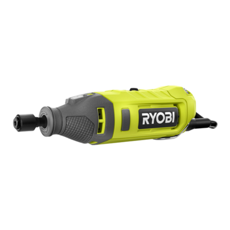
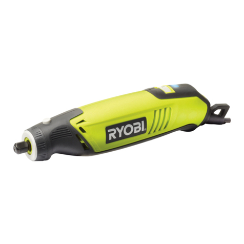
Ryobi EHT150V User manual

GB USER’S MANUAL 1
FR MANUEL D’UTILISATION 11
DE BEDIENUNGSANLEITUNG 21
ES MANUAL DE UTILIZACIÓN 31
IT MANUALE D’USO 41
NL GEBRUIKSHANDLEIDING 51
PT MANUAL DE UTILIZAÇÃO 61
DK BRUGERVEJLEDNING 71
SE INSTRUKTIONSBOK 81
FI KÄYTTÄJÄN KÄSIKIRJA 91
NO BRUKSANVISNING 100
RU РУКОВОДСТВО ПО ЭКСПЛУАТАЦИИ 109
PL INSTRUKCJA OBSŁUGI 120
CZ NÁVOD K OBSLUZE 130
HU HASZNÁLATI ÚTMUTATÓ 139
RO MANUAL DE UTILIZARE 149
LV LIETOTĀJA ROKASGRĀMATA 159
LT NAUDOJIMO VADOVAS 169
EE KASUTAJAJUHEND 179
HR KORISNIČKI PRIRUČNIK 189
SI UPORABNIŠKI PRIROČNIK 199
SK NÁVOD NA POUŽITIE 209
GR ΟΔΗΓΙΕΣ ΧΡΗΣΗΣ 219
TR KULLANiM KILAVUZU 230
EHT150V
GB
original instructions |
FR
traduction des instructions originales |
DE
übersetzung der originalanleitung
| ES
traducción de las
instrucciones originales |
IT
traduzione delle istruzioni originali |
NL
vertaling van de originele instructies |
PT
tradução das instruções
originais |
DK
oversættelse af de originale instruktioner |
SE
översättning av de ursprungliga instruktionerna |
FI
alkuperäisten
ohjeiden suomennos |
NO
oversettelse av de originale instruksjonene |
RU
перевод оригинальных инструкций |
PL
tłumaczenie instrukcji
oryginalnej |
CZ
překlad originálních pokynů |
HU
az eredeti útmutató fordítása |
RO
traducerea instrucţiunilor originale |
LV
tulkots
no oriģinālās instrukcijas |
LT
originalių instrukcijų vertimas |
EE
originaaljuhendi tõlge |
HR
prijevod originalnih uputa |
SI
prevod
originalnih navodil
| SK
preklad originálneho návodu
| GR
μετάφράση των πρωτότυπων όδηγιων
| TR
orijinal talimatlarin tercümesi
ROTARY TOOL
OUTIL ROTATIF
ROTATIONSWERKZEUG
MULTI HERRAMIENTA
UTENSILE ROTANTE
ROTATIEGEREEDSCHAP
FERRAMENTA ROTATIVA
ROTATIONSVÆRKTØJ
SNABBROTERANDE VERKTYG
MONITOIMILAITE
ROTERENDE VERKTØY
ФРЕЗА
UNIWERSALNE NARZĘDZIE OBROTOWE
ROTAČNÍ NÁSTROJ
MULTIFUNKCIÓS SZERSZÁM
UNEALTĂ ROTATIVĂ
PAGRIEŽAMS INSTRUMENTS
SUKAMASIS ĮRANKIS
PÖÖRDLÕIKUR
ROTACIJSKI ALAT
VRTALNO ORODJE
ROTAČNÉ NÁRADIE
ΠΕΡΙΣΤΡΕΦΟΜΕΝΟ ΕΡΓΑΛΕΙΟ
DÖNER ALET

Fig. 1
24
22
23
Fig. 2 Fig. 4Fig. 3
7
16
2
816
9
2
3
4
34
5
4
2
1
3
34

11
12
13
14
1
6
Fig. 5
Fig. 8
Fig. 7
Fig. 10
Fig. 6
Fig. 9
16
17
21
3
20
18
19
2
15
10

33
Fig. 11 Fig. 12
Fig. 13 Fig. 14
31
32
1
7
25
26
24
27
23
5
29
30
28
16
936
35
2


1
English
GB
FR DE ES IT NL PT DK SE FI NO RU PL CZ HU RO LV LT EE HR SI SK GR TR
SPECIAL SAFETY RULES
Hold tool by insulated gripping surfaces when
performing an operation where the cutting tool
may contact hidden wiring or its cord. Contact with
a “live” wire will also make exposed metal parts of the
power tool “live” and shock the operator.
Inspect for and remove all nails from lumber
before using this tool. Following this rule will reduce
the risk of serious personal injury.
Do not reach in the area of the spinning bit. The
proximity of the spinning bit to your hand may not
always be obvious.
This product is not intended for use as a dental drill
or in human or veterinary medical applications.
Serious injury may result.
When using steel screws, cut-off wheels, high
speed cutters, or tungsten carbide cutters, always
have the work securely clamped. Never attempt to
hold the work with one hand while using any of
these accessories.
ADDITIONAL SAFETY INSTRUCTIONS FOR
YOUR MINI GRINDER
This power tool is intended to function as a
grinder. Read all safety warnings, instructions,
illustrations and specifications provided with this
power tool. Failure to follow all instructions listed
below may result in electric shock, fire and/or serious
injury.
Do not use accessories which are not specifically
designed and recommended by the tool
manufacturer. Just because the accessory can be
attached to your power tool, it does not assure safe
operation.
The rated speed of the accessory must be at least
equal to the maximum speed marked on the power
tool. Accessories running faster than their rated speed
can break and fly apart.
The outside diameter and the thickness of your
accessory must be within the capacity rating of
your power tool. Incorrectly sized accessories cannot
be adequately guarded or controlled.
The arbour size of wheels, flanges, backing pads
or any other accessory must properly fit the
spindle of the power tool. Accessories with arbour
holes that do not match the mounting hardware of the
power tool will run out of balance, vibrate excessively
and may cause loss of control.
Do not use a damaged accessory. Before each use
inspect the accessory such as abrasive wheels for
chips and cracks, backing pad for cracks, tear or
excess wear, wire brush for loose or cracked wires.
If power tool or accessory is dropped, inspect for
damage or install an undamaged accessory. After
inspecting and installing an accessory, position
yourself and bystanders away from the plane of
the rotating accessory and run the power tool at
maximum no-load speed for one minute. Damaged
accessories will normally break apart during this test
time.
Wear personal protective equipment. Depending
on application, use face shield, safety goggles
or safety glasses. As appropriate, wear dust
mask, hearing protectors, gloves and workshop
apron capable of stopping small abrasive or
workpiece fragments. The eye protection must
be capable of stopping flying debris generated by
various operations. The dust mask or respirator must
be capable of filtrating particles generated by your
operation. Prolonged exposure to high intensity noise
may cause hearing loss.
Keep bystanders a safe distance away from work
area. Anyone entering the work area must wear
personal protective equipment. Fragments of
workpiece or of a broken accessory may fly away and
cause injury beyond immediate area of operation.
Hold power tool by insulated gripping surfaces
only, when performing an operation where the
cutting accessory may contact hidden wiring or its
own cord. Cutting accessory contacting a “live” wire
may make exposed metal parts of the power tool “live”
and shock the operator.
Position the cord clear of the spinning accessory.
If you lose control, the cord may be cut or snagged
and your hand or arm may be pulled into the spinning
accessory.
Never lay the power tool down until the accessory
has come to a complete stop. The spinning
accessory may grab the surface and pull the power
tool out of your control.
Do not run the power tool while carrying it at your
side. Accidental contact with the spinning accessory
could snag your clothing, pulling the accessory into
your body.
Regularly clean the power tool’s air vents. The
motor’s fan will draw the dust inside the housing
and excessive accumulation of powdered metal may
cause electrical hazards.
Do not operate the power tool near flammable
materials. Sparks could ignite these materials.
Do not use accessories that require liquid
coolants. Using water or other liquid coolants may
result in electrocution or shock.
2
English
GB
FR DE ES IT NL PT DK SE FI NO RU PL CZ HU RO LV LT EE HR SI SK GR TR
Kickback and related warnings
Kickback is a sudden reaction to a pinched or snagged
rotating wheel, backing pad, brush or any other accessory.
Pinching or snagging causes rapid stalling of the rotating
accessory which in turn causes the uncontrolled power tool
to be forced in the direction opposite of the accessory's
rotation at the point of the binding. For example, if an
abrasive wheel is snagged or pinched by the workpiece,
the edge of the wheel that is entering into the pinch point
can dig into the surface of the material causing the wheel
to climb out or kick out. The wheel may either jump toward
or away from the operator, depending on direction of the
wheel’s movement at the point of pinching.
Abrasive wheels may also break under these conditions.
Kickback is the result of power tool misuse and/or incorrect
operating procedures or conditions and can be avoided by
taking proper precautions as given below.
Maintain a firm grip on the power tool and
position your body and arm to allow you to resist
kickback forces. Always use auxiliary handle, if
provided, for maximum control over kickback or
torque reaction during start-up. The operator can
control torque reactions or kickback forces, if proper
precautions are taken.
Never place your hand near the rotating accessory.
Accessory may kickback over your hand.
Do not position your body in the area where power
tool will move if kickback occurs. Kickback will
propel the tool in direction opposite to the wheel’s
movement at the point of snagging.
Use special care when working corners, sharp
edges etc.
Avoid bouncing and snagging the accessory.
Corners, sharp edges or bouncing have a tendency to
snag the rotating accessory and cause loss of control
or kickback.
Do not attach a saw chain woodcarving blade or
toothed saw blade. Such blades create frequent
kickback and loss of control.
Safety warnings specific for grinding operations:
Use only wheel types that are recommended for
your power tool and the specific guard designed
for the selected wheel. Wheels for which the power
tool was not designed cannot be adequately guarded
and unsafe.
The guard must be securely attached to the power
tool and positioned for maximum safety, so the
least amount of wheel is exposed towards the
operator. The guard helps to protect operator from
broken wheel fragments and accidental contact with
wheel and sparks that could ignite clothing.
Wheels must be used only for recommended
applications. For example, do not grind with the
side of cut-off wheel. Abrasive cut-off wheels are
intended for peripheral grinding, side forces applied to
these wheels may cause them to shatter.
Always use undamaged wheel flanges that are of
correct size and shape for your selected wheel.
Proper wheel flanges support the wheel thus reducing
the possibility of wheel breakage. Flanges for cut-off
wheels may be different from grinding wheel flanges.
Do not use worn down wheels from larger power
tools. Wheel intended for larger power tool is not
suitable for the higher speed of a smaller tool and may
burst.
SYMBOL
Safety Alert
V Volts
Hz Hertz
Alternating Current
WWatts
J Joules
noNo-load speed
min-1Revolutions or reciprocations per minute
CE Conformity
Double insulation
Wear ear protection
Wear eye protection
Please read the instructions carefully before
starting the machine.
Waste electrical products should not be
disposed of with household waste. Please
recycle where facilities exist. Check with your
Local Authority or retailer for recycling advice.
ELECTRICAL
DOUBLE INSULATION
Double insulation is a concept in safety in electric power
tools, which eliminates the need for the usual three-wire
grounded power cord. All exposed metal parts are isolated

3
English
GB
FR DE ES IT NL PT DK SE FI NO RU PL CZ HU RO LV LT EE HR SI SK GR TR
from the internal metal motor components with protecting
insulation. Double insulated tools do not need to be
grounded.
WARNING
The double insulated system is intended to protect the
user from shock resulting from a break in the internal
insulation of the product. Observe all normal safety
precautions to avoid electrical shock.
NOTE: Servicing of a product with double insulation
requires extreme care and knowledge of the system and
should be performed only by a qualified service technician.
For service, we suggest you return the product to your
nearest authorized service center for repair. Always use
original factory replacement parts when servicing.
ELECTRICAL CONNECTION
This product has a precision-built electric motor. It should
be connected to a power supply that is 230 V, AC only
(normal household current), 60 Hz. Do not operate this
product on direct current (DC). A substantial voltage drop
will cause a loss of power and the motor will overheat. If
the product does not operate when plugged into an outlet,
double check the power supply.
EXTENSION CORDS
When using a power tool at a considerable distance
from a power source, be sure to use an extension cord
that has the capacity to handle the current the product
will draw. An undersized cord will cause a drop in line
voltage, resulting in overheating and loss of power. Use
the chart to determine the minimum wire size required in
an extension cord.
When working outdoors with a product, use an extension
cord that is designed for outside use.
WARNING
Some dust created by power sanding, sawing, grinding,
drilling, and other construction activities contains
chemicals known to cause cancer, birth defects or other
reproductive harm. Some examples of these chemicals
are:
lead from lead-based paints
crystalline silica from bricks and cement and
other masonry products
arsenic and chromium from chemically-treated
lumber
Your risk from these exposures varies, depending on
how often you do this type of work. To reduce your
exposure to these chemicals, work in a well ventilated
area, and work with approved safety equipment, such
as those dust masks that are specially designed to filter
out microscopic particles.
DESCRIPTION
1. Collet nut
2. Spindle lock
3. Speed control dial
4. On/off switch
5. Tool loop
6. Collet
7. Wrench
8. Accessories
9. Spindle
10. Grinding wheel bits
11. Mandrel screw
12. Washer
13. Cut-off disc
14. Mandrel
15. To tighten
16. Fiberglass cut-off wheel
17. Sanding drums
18. Indicator mark
19. Low speed
20. High speed
21. Pencil holding method
22. Telescoping tool hanger
23. Flex shaft
24. Clamp-on base
25. Tool hanger hook
26. Tool hanger
27. Clamp screw
28. Drive shaft
29. Collar
30. Cup end of flex shaft
31. Locking key
32. Hole

4
English
GB
FR DE ES IT NL PT DK SE FI NO RU PL CZ HU RO LV LT EE HR SI SK GR TR
33. Grooved gripping section
34. Live tool indicator
35. Collet sleeve
36. Tool head
SPECIFICATIONS
Input 230 V - 240 V 50 Hz
Rated speed 10,000-35,000 (RPM) min-1
Collet 3.2 mm max.
Weight 0.73 kg
OPERATION
WARNING
Do not allow familiarity with tools to make you careless.
Remember that a careless fraction of a second is
sufficient to inflict serious injury.
WARNING
Always wear eye protection. Failure to do so could
result in objects being thrown into your eyes, resulting
in possible serious injury.
WARNING
Do not use any attachments or accessories not
recommended by the manufacturer of the product. The
use of attachments or accessories not recommended
can result in serious personal injury.
APPLICATIONS
You may use this product for the purposes listed below:
Cutting
Sanding
Polishing and buffing
Engraving
Drilling
Grinding
TURNING THE ROTARY TOOL ON/OFF
See Figure 2.
To turn the tool on: Slide the switch to “|”.
To turn the tool off: Slide the switch to “O”.
CAUTION
To prevent damage to the spindle or spindle lock,
always allow motor to come to a complete stop before
engaging the spindle lock.
CHANGING COLLETS
See Figure 3.
Unplug the tool.
Press and hold the spindle lock, and rotate the shaft
with the provided collet wrench until the spindle lock
engages the shaft, preventing further rotation.
With the spindle lock engaged, use the collet wrench
to loosen the collet nut, if necessary.
Remove the collet nut and old collet using collet
wrench, if necessary.
Insert the unslotted end of the collet in the hole in the
end of the tool shaft.
Replace the collet nut on the shaft.
WARNING
Always use the collet which matches the shank size
of the accessory you plan to use. Never force a large
diameter shank into a collet. The accessory should
fit smoothly into the collet, but you should be able to
tighten the accessory firmly and securely with the
provided wrench.
DANGER
If you are changing an accessory immediately after
use, be careful not to touch the collet, collet nut, or
the accessory with your hands or fingers. You will
get burned because of the heat build-up from cutting.
Always use the wrench provided.
INSTALLING ACCESSORIES
See Figure 4–5.
Unplug the tool.
Press and hold the spindle lock, and rotate the shaft
by hand until the spindle lock engages the shaft,
preventing further rotation.
With the spindle lock engaged, use the collet wrench
to loosen the collet nut, if necessary.
Insert the shank of the accessory into the collet until
the shank bottoms out, then pull it out 1.6 mm (1/16 in)
to allow for expansion when the accessory gets hot.
With the spindle lock engaged, tighten the collet nut

5
English
GB
FR DE ES IT NL PT DK SE FI NO RU PL CZ HU RO LV LT EE HR SI SK GR TR
with the provided wrench until the accessory shank is
gripped by the collet. Avoid excessive tightening of the
collet nut.
REMOVING ACCESSORIES
See Figure 4–5.
Unplug the tool.
With the spindle lock engaged, loosen the collet nut
with the provided wrench.
Remove the accessory. If still cannot be removed,
push the accessory back into the collet nut, then
loosen and remove it.
USING MANDRELS
See Figure 6–8.
The most common types of mandrel to use with this tool
are the standard mandrel which is used with cut-off discs,
grinding wheels, emery wheels, and cut-off wheels. Screw
mandrels are used with polishing wheels and polishing
drums. Drum mandrels are used with sanding drums.
To install:
Unplug the tool.
Install the mandrel.
If using the standard mandrel:
Press and hold the spindle lock.
Insert the slot end of the provided wrench into the slot
on top of the mandrel and unscrew.
Remove mandrel screw and washer.
Place desired accessory over mandrel shaft and align
accessory hole with mandrel hole.
Insert mandrel screw with washer through the
accessory and mandrel shaft holes.
NOTE: The mandrel washer should be placed between
the mandrel screw and the accessory.
Tighten using provided wrench.
If using the screw mandrel:
Align desired accessory hole with mandrel screw
head.
Screw accessory onto mandrel by twisting clockwise
until secure.
If using the drum mandrel:
Align appropriately sized sanding drum over mandrel
and push down to completely cover drum end of
mandrel.
NOTE: If necessary, tighten the screw on the drum
mandrel head to expand the drum and securely hold the
sanding drum in place.
BALANCING ACCESSORIES
For precision work, it is important that all accessories
be properly balanced. To balance an accessory, slightly
loosen the collet nut and give the accessory or collet a
6.35 mm (1/4 in) turn. You should be able to tell by the
sound and feel if the accessory is running in balance.
Continue adjusting in this fashion until the best balance is
achieved. Replace accessories if they become damaged
or unbalanced.
SELECTING THE RIGHT SPEED
See Figure 9.
The rotary tool has a speed range of 10,000 to 35,000
RPM. To select the right speed for each job, use a practice
piece of material. Vary speed to find the best speed for the
accessory you are using and the job to be done.
Use the indicator mark above the speed control dial to
set the best speed for the job. The speed control dial is
numbered 1 to 5 and MAX. For example, a speed setting
of 1 is approximately 10,000 RPM, and a speed setting of
MAX is approximately 35,000 RPM.
Refer to the speed dial settings table to determine the
proper speed based on the material being worked and the
type of accessory being used.
SLOWER SPEEDS
Certain materials, some plastics for example, require
a relatively slow speed because the friction of the tool
generates heat and causes the plastic to melt at high
speed.
Slow speeds (15,000 RPM or less) are usually best for
polishing operations using the polishing accessories. They
may also be best for working on delicate projects, delicate
wood carving, and fragile model parts.
Higher speeds are better for carving, cutting, and shaping
wood. Hardwoods, metals, and glass require high speed
operation. Drilling should also be done at high speeds.
To determine the optimum operational speed for different
materials and accessories, refer to the speed dial settings
table. Look this table over and become familiar with it.
The best way to determine the correct speed for work on
any material is to practice for a few minutes on a piece of
scrap, even after referring to the table. You can quickly
learn whether a slower or faster speed is more effective
just by observing what happens when you make a pass or
two at different speeds.
When working with a scrap piece of plastic, start from
a slow rate of speed and increase the speed until you
observe the plastic is melting at the point of contact;
reduce the speed slightly to get optimum working speed

6
English
GB
FR DE ES IT NL PT DK SE FI NO RU PL CZ HU RO LV LT EE HR SI SK GR TR
without melting the workpiece.
NOTE:
Plastic and materials that could melt at slow
temperatures should be cut at low speeds.
Soft wood should be cut at high speed.
Aluminum, tin, copper, lead, and zinc alloys may
be cut at any speed, depending on the type of
cutting being done. Use paraffin or other suitable
lubricant on the cutter to prevent the cut material
from adhering to the cutter teeth.
For more information, see table on speed dial settings.
OPERATING THE ROTARY TOOL
See Figure 10.
Learning to use the rotary tool:
Hold the tool in your hand and get used to its weight,
balance, and the taper of the housing. This taper
permits the tool to be grasped like a pencil.
Examine the rotary tool accessories carefully.
Damaged accessories can fly apart as they come up
to speed and should not be used. The use of damaged
accessories can result in serious personal injury.
Practice on scrap materials first to see how the tool
operates. Keep in mind that the work is done by the
speed of the tool and by the accessory in the collet.
You should not lean on or push the tool into the work.
It is best to make a series of passes with the tool rather
than attempt to do all the work in one pass. To make a
cut, pass the tool back and forth over the work like you
would a small paint brush. Cut a little material on each
pass until you reach the desired depth. For most work, a
gentle touch is best; you will have greater control, make
fewer errors, and get the most efficient work out of the
accessory.
For the best control in close work, grip the tool like a pencil
between your thumb and forefinger. A “hand grip” method
of holding the tool is used for operations such as grinding
a flat surface or using cut-off discs.
To operate the rotary tool:
Secure all work in a vise or clamp to a workbench to
prevent it from moving under the tool.
NOTE: To operate the rotary tool using the flex shaft, grip
the flex shaft along the grooved gripping section.
Hold the tool in front and away from you, keeping the
tool accessory clear of the workpiece.
Turn on the tool and let the motor and accessory build
up to full speed.
Lower the tool gradually until the accessory contacts
the workpiece.
Move the tool continuously at a steady, consistent
pace.
Use just enough pressure to keep the tool from
chattering or bouncing.
NOTE: Heavy pressure will decrease the tool’s speed and
put a strain on the motor. The weight of the tool alone is
adequate for most jobs.
Lift the tool away from the workpiece before turning
off the tool.
TELESCOPING TOOL HANGER WITH CLAMP ON
BASE
See Figure 11.
The telescoping tool hanger provides a convenient place
to hang the rotary tool while the flex shaft is in use.
To clamp the base to a worktable:
Turn the clamp screw counterclockwise to open the
clamping area.
Place clamp over the edge of worktable.
Turn the clamp screw clockwise until the clamp is
secure.
To attach the tool hanger to the base:
Turn the lower part of the tool hanger clockwise to
unlock.
Pull the tool hanger up to lengthen or push the tool
hanger down to shorten its height.
Turn the lower part of the tool hanger counterclockwise
to lock into place.
Screw the tool hanger into the top of the clamp.
NOTE: When using the flex shaft, hang the rotary tool on
the tool hanger hook using the hook located on the back
of the rotary tool.
OPERATING THE FLEX SHAFT
See Figure 12–14.
The 3.2 mm collet must be inserted into the rotary tool
before the flex shaft can be installed. To install the flex
shaft:
Unplug the tool.
Loosen collet sleeve by turning counterclockwise, then
remove.
Press and hold the spindle lock, and rotate the shaft
by hand until the spindle lock engages the shaft,
preventing further rotation.
With the spindle lock engaged, use the collet wrench
to loosen the collet nut, if necessary.
Remove collet nut and collet.

7
English
GB
FR DE ES IT NL PT DK SE FI NO RU PL CZ HU RO LV LT EE HR SI SK GR TR
Insert the 3.2 mm collet.
Replace and tighten the collet nut.
Insert drive shaft into collet nut until the collar meets
the collet nut.
Tighten the collet nut completely, keeping collar in
contact with the collet nut.
Insert cup end of flex shaft onto tool head. Turn
clockwise to tighten.
To install accessories into the flex shaft:
Unplug the tool.
Locate the hole behind the collet nut in the flex shaft
body.
Turn the collet nut until the hole in the flex shaft body
aligns with the hole visible inside the flex shaft.
Insert provided locking key into the aligned holes to
lock collet nut into place.
Loosen the collet nut.
Insert the shank of the accessory into the collet nut
until the shank bottoms out, then pull it out 1.6 mm
to allow for expansion when the accessory gets hot.
With the key still in place, tighten the collet nut with the
provided wrench until the accessory shank is gripped
by the collet. Avoid excessive tightening of the collet
nut.
Remove the key.
To remove accessories from the flex shaft:
Unplug the tool.
Locate the hole behind the collet nut in the flex shaft
body.
Turn the collet nut until the hole in the flex shaft body
aligns with the hole visible inside the flex shaft.
Insert provided locking key into the aligned holes to
lock collet nut into place.
With the key still in place, loosen the collet nut with the
provided wrench.
Remove the accessory.
LIVE TOOL INDICATOR
This tool features a live tool indicator which illuminates as
soon as the tool is connected to the supply. This warns the
user that the tool is connected and will operate when the
switch is pressed.
MAINTENANCE
WARNING
When servicing, use only identical replacement parts.
Use of any other parts may create a hazard or cause
product damage.
Avoid using solvents when cleaning plastic parts. Most
plastics are susceptible to damage from various types of
commercial solvents and may be damaged by their use.
Use clean cloths to remove dirt, dust, oil, grease, etc.
WARNING
Do not at any time let brake fluids, gasoline, petroleum-
based products, penetrating oils, etc., come in contact
with plastic parts. They contain chemicals that can
damage, weaken or destroy plastic.
Do not abuse power tools. Abusive practices can damage
tool as well as workpiece.
WARNING
Do not attempt to modify this tool or create accessories
not recommended for use with this tool. Any such
alteration or modification is misuse and could result
in a hazardous condition leading to possible serious
personal injury.
Electric tools used on fiberglass material, wallboard,
spackling compounds, or plaster are subject to
accelerated wear and possible premature failure because
the fiberglass chips and grindings are highly abrasive to
bearings, brushes, commutators, etc.
Consequently, we do not recommend using this tool for
extended work on these types of materials. However, if
you do work with any of these materials, it is extremely
important to clean the tool using compressed air.
LUBRICATION
All of the bearings in this tool are lubricated with a
sufficient amount of high grade lubricant for the life of
the unit under normal operating conditions. Therefore, no
further lubrication is required.
POWER SUPPLY CORD REPLACEMENT
If replacement of the power supply cord is necessary, this
must be done by an authorized service center in order to
avoid a safety hazard.

8
English
GB
FR DE ES IT NL PT DK SE FI NO RU PL CZ HU RO LV LT EE HR SI SK GR TR
ENVIRONMENTAL PROTECTION
Recycle raw materials instead of disposing
of as waste. The machine, accessories
and packaging should be sorted for
environmental-friendly recycling.
SPEED DIAL SETTINGS
Type of
accessory Soft wood Hard
wood
Laminates
plastics Steel Aluminum,
brass, etc.
Shell/
stone Ceramic Glass
Cut-off
discs — — — 1-3 — — — —
Fiberglass
cut-off
wheel
— — 1-3 — 1-5 — — —
Sanding
drums 3-MAX 3-MAX 1-3 4-MAX 4-MAX — — —
Felt
polishing
wheels
— — — 3-5 3-5 3-5 3-5 3-5
Aluminum
oxide
grinding
stones
— — — 3-5 — — — —
Silicon
carbide
grinding
stone
— — — — 1-2 1-2 4-MAX 4-MAX
Drill bit 4-MAX 4-MAX 1-3 4-MAX 4-MAX — — —
Drywall
cutting bit 4-MAX (drywall only)

9
English
GB
FR DE ES IT NL PT DK SE FI NO RU PL CZ HU RO LV LT EE HR SI SK GR TR
ACCESSORY TABLE
Figure Accessories Applications
Collet (Ø 3.2 mm)
Attaching bits
Collet (Ø 1.6 mm)
Orange 120-grit aluminum oxide grinding
wheel bits (Ø 3.2 mm shank/collet)
Ferrous materials:
casting, welds, rivets, rust
Green 120-grit silicon carbide grinding
wheel bit (Ø 3.2 mm shank/collet)
Non-ferrous materials:
stone, ceramics, porcelain, glass
Drum sander mandrel (Ø 6.4 mm)
(Ø 3.2 mm shank/collet) Attaching sanding drums
Drum sander mandrel (Ø 12.7 mm)
(Ø 3.2 mm shank/collet)
Polishing compound vial Polishing and brightening metals and
plastics
Cut-off discs (Ø 23.8 mm x Ø 0.8 mm) Cutting ferrous materials
Pink 220-grit aluminum oxide grinding
wheel (Ø 19 mm)
Ferrous materials:
casting, welds, rivets, rust
Sanding drums (60-grit and 120-grit)
(Ø 6.4 mm x Ø 12.7 mm) Sanding wood, metals and plastics
Sanding drums (60-grit and 120-grit)
(Ø 12.7 mm x Ø 12.7 mm)
Silicon carbide dressing stone Bringing shape back to parabolic shaped
grinding attachments
Felt polishing wheels (25.4 mm x 12.7
mm)
Polishing and buffing metals, stone, glass
and ceramics
Cloth polishing wheel (25.4 x 6 mm) Polishing and buffing
Fiberglass cut-off wheel (Ø 31.8 mm) Cutting and trimming metals, plastics and
ceramics
Screw mandrel (Ø 3.2 mm shank/collet) Attaching felt attachments
Mandrel (Ø 3.2 mm shank x 1.6 mm) Attaching cut-off discs, cut-off wheels,
grinding wheels, and emery wheels
High speed steel drill bit (Ø 1.6 mm shank/
collet) Drilling

10
English
GB
FR DE ES IT NL PT DK SE FI NO RU PL CZ HU RO LV LT EE HR SI SK GR TR
ACCESSORY TABLE
Drywall cutting bit (Ø 3.2 mm shank/collet) Cutting drywall
Wrench Removing attachments
Telescoping tool hanger Hanging the rotary tool while using the flex
shaft
Flex shaft (915 mm) Allowing fingertip control to cut, sand,
polish, etc.
Clamp-on base Attaching the tool hanger on the base
Locking key Locking the spindle of flex shaft to replace
the accessory

11
Français
FR
GB DE ES IT NL PT DK SE FI NO RU PL CZ HU RO LV LT EE HR SI SK GR TR
RÈGLES PARTICULIÈRES DE SÉCURITÉ
Ne tenez l'outil que par les parties isolées et
antidérapantes lorsque vous travaillez sur une
surface pouvant cacher des fils électriques. Un
contact avec des fils sous tension pourrait transmettre
le courant dans les parties en métal et provoquer un
choc électrique.Continuez cette opération jusqu'à
atteindre le meilleur équilibrage.
Vérifiez l'absence de clous dans le bois avant
d'utiliser cet outil. Vous réduirez ainsi les risques de
blessures graves.
Restez à l'écart de la zone du foret en rotation. La
proximité de l'embout tournant avec votre main n'est
pas toujours évidente.
Ce produit n'est pas destiné à être utilisé comme
une fraise de dentiste ou pour des applications
médicales ou vétérinaires. De graves blessures
pourraient en résulter.
Lorsque vous utilisez des vis en acier, des meules
à découper, des disques de coupe à haute vitesse,
ou des disques en carbure de tungstène, fixez
toujours fermement la pièce à usiner. Ne tentez
jamais de tenir l'outil d'une main lorsque vous
utilisez l'un de ces accessoires.
INSTRUCTIONS DE SÉCURITÉ
COMPLÉMENTAIRES POUR VOTRE MINI
MEULEUSE
Le but de cet outil électrique est d'être utilisé
comme une meuleuse. Lisez attentivement
l’ensemble des avertissements, instructions
et spécifications fournis avec cet outil, et
reportez-vous aux illustrations. Le non-respect
des instructions présentées ci-après peut entraîner
des accidents tels que des incendies, des chocs
électriques et/ou des blessures corporelles graves.
N’utilisez pas des accessoires qui ne sont pas
spécifiquement conçus pour cet outil et qui ne
sont pas recommandés par le fabricant Même si un
accessoire peut être monté sur un outil, cela ne garantit
pas que vous pourrez utiliser cet outil en toute sécurité.
La vitesse nominale de l’accessoire doit être égale
ou supérieure à la vitesse maximale indiquée sur
l’outil. Les accessoires fonctionnant à une vitesse
supérieure à leur vitesse nominale peuvent se casser
et être éjectés.
Le diamètre extérieur et l’épaisseur de l’accessoire
doivent correspondre aux caractéristiques
spécifiées pour l’outil Si les accessoires ne
correspondent pas aux caractéristiques données,
les systèmes de protection et de réglage de l’outil ne
pourront pas fonctionner correctement.
Les meules, flasques, patins ou autres accessoires
doivent être parfaitement adaptés à l’alésage de
l’arbre de l’outil. Les accessoires non adaptés à
l’arbre sur lequel ils doivent être montés ne tourneront
pas correctement, vibreront de manière excessive et
vous feront perdre le contrôle de l’outil.
N’utilisez pas un accessoire endommagé. Avant
chaque utilisation, vérifiez que l’accessoire que
vous utilisez est en bon état:assurez-vous que les
disques abrasifs ne sont pas ébréchés ou fissurés,
que les patins ne sont pas déchirés ou usés, que
les poils des brosses métalliques ne sont pas
trop usés ou cassés. En cas de chute de l’outil ou
de l’accessoire, vérifiez qu’aucun élément n’est
endommagé et, si besoin, installez un accessoire
neuf. En cas de chute de l’outil ou de l’accessoire,
vérifiez qu’aucun élément n’est endommagé et, si
besoin, installez un accessoire neuf. Si l’accessoire
est endommagé, il se cassera pendant ce test.
Porter des équipements de protection individuelle.
Selon l’utilisation que vous faites de votre outil,
portez un masque de protection, des lunettes de
sécurité ou des lunettes de protection. Si besoin,
portez un masque anti-poussière, des protections
auditives, des gants et un tablier de protection
afin de vous protéger de toute projection de corps
étrangers (éléments abrasifs, copeaux de bois, etc.).
Les masques anti-poussière permettent de filtrer les
particules générées par l’opération que vous menez.
L’exposition prolongée à un bruit de forte intensité
peut entraîner une perte d’audition. Maintenez les
visiteurs à bonne distance de la zone de travail
et veillez à ce qu’ils portent un équipement de
protection. Des fragments de pièce à usiner ou d’un
accessoire cassé peuvent être projetés au-delà de la zone
de travail et causer des blessures corporelles graves.
Ne tenez l’outil que par les parties isolées et
antidérapantes lorsque vous travaillez sur une
surface pouvant cacher des fils électriques ou
lorsque le travail requis est susceptible de placer
le cordon d’alimentation sur la trajectoire de
l’outil. Un contact avec des fils sous tension pourrait
transmettre le courant dans les parties en métal et
provoquer un choc électrique.
Positionnez le cordon d’alimentation de façon à
ce qu’il soit à distance de l’accessoire en rotation.
Si vous perdez le contrôle de votre outil, le cordon
d’alimentation pourrait être coupé ou se coincer et
votre main ou votre bras pourrait être entraîné vers
l’accessoire en rotation.
Ne posez jamais votre outil avant que l’accessoire
ne soit complètement arrêté L’accessoire en rotation
pourrait entrer en contact avec la surface sur laquelle
il est posé et vous faire perdre le contrôle de l’outil.

12
Français
FR
GB DE ES IT NL PT DK SE FI NO RU PL CZ HU RO LV LT EE HR SI SK GR TR
Ne faites pas fonctionner votre outil lorsque vous
le transportez L’accessoire en rotation pourrait
se prendre dans vos vêtements et vous blesser
gravement.
Nettoyez régulièrement les fentes de ventilation
de l’outil. La ventilation du moteur fait pénétrer les
poussières à l’intérieur du carter moteur, ce qui peut
générer une accumulation excessive de particules
métalliques et provoquer des chocs électriques.
N’utilisez pas votre outil à proximité de produits
inflammables Des étincelles risqueraient de les enflammer.
N’utilisez pas d’accessoires nécessitant des
fluides de refroidissement L’utilisation d’eau ou
de liquides de refroidissement peut causer des
électrocutions ou des chocs électriques.
Avertissements relatifs au rebond et autres risques
associés
Le rebond est une réaction soudaine qui a lieu lorsque
la meule en mouvement, le patin, la brosse ou tout autre
accessoire se pince ou se tord, ce qui entraîne le blocage
rapide de l’accessoire L’outil, qui continue à fonctionner, est
alors projeté dans la direction opposée au sens d’utilisation
de l’accessoire. Par exemple, si un disque abrasif se pince
ou se tord dans la pièce à usiner, le tranchant du disque
risque de s’enfoncer dans la surface de la pièce à usiner,
ce qui fera brusquement sortir le disque de la pièce à usiner
et le projettera vers l’utilisateur ou à distance, en fonction du
sens de rotation du disque lorsque celui-ci s’est bloqué En
cas de rebond, le disque abrasif peut également se casser.
Le rebond est donc le résultat d’une mauvaise utilisation de l’outil
et/ou de procédures ou de conditions d’utilisation incorrectes
Il peut être évité en veillant à respecter quelques
précautions:
Maintenez fermement l’outil et positionnez votre
corps et votre bras de façon à pouvoir contrôler un
éventuel rebond Si l’outil dispose d’une poignée
auxiliaire, veillez à toujours la tenir pour avoir un
contrôle optimal de l’outil en cas de rebond ou
de couple de réaction lors de la mise en marche
de l’outil. Prenez les mesures nécessaires afin de
pouvoir contrôler votre outil en cas de rebond ou de
couple de réaction.
Ne placez jamais votre main à proximité de
l’accessoire en rotation afin d’éviter tout risque
de blessures corporelles graves en cas de rebond.
Accessoire risque de rebondir sur votre main.
Ne vous placez pas dans la zone où l’outil risque
d’être projeté en cas de rebond En cas de rebond,
l’outil est projeté dans la direction opposée au sens de
rotation du disque.
Faites particulièrement attention lorsque vous
travaillez sur des angles, des bords tranchants,
etc
Évitez de faire déraper ou de coincer l’accessoire.
Lorsque vous travaillez sur des angles ou des bords
tranchants ou lorsque vous faites déraper l’outil, le
risque est plus élevé de bloquer l’accessoire, et donc
de perdre le contrôle de l’outil et provoquer un rebond.
N’utilisez jamais de lame de tronçonneuse à
bois ou de lame de scie avec cet outil. De telles
lames augmentent le risque de rebond et de perte de
contrôle de l’outil.
Avertissements de sécurité particuliers pour les
opérations de meulage:
N'utilisez que des types de meule recommandés
pour votre outil électrique ainsi que la protection
spécifique à la meule utilisée. Les meules pour
lesquelles l'outil électrique n'a pas été prévu ne
peuvent pas être protégées de façon adéquate et
présentent un danger.
La protection doit être bien fixée sur l'outil
électrique et positionnée de façon à offrir la
meilleure sécurité, afin que la plus petite partie
possible de la meule soit dirigée vers l'opérateur.
Le carter de protection aide à protéger l'opérateur
des fragments cassés du disque et des contacts
accidentels avec le disque ainsi que des étincelles
susceptible de mettre le feu aux vêtements.
Les meules ne doivent être utilisées que dans leur
domaine d'application recommandé. Par exemple,
n'utilisez pas le flanc d'un disque à tronçonner
pour meuler. Les disques abrasifs de découpe sont
destinés à des découpes périphériques, les forces
latérales y étant appliquées peuvent entraîner leur
bris.
Assurez-vous de toujours utiliser des supports de
disques en bon état et dont la taille et la forme sont
adaptées au disque à utiliser. Un support de disque
adapté maintient le flanc du disque et réduit le risque
de bris. Les supports des disques à découper peuvent
être différents des supports pour meules.
N'utilisez pas de disques usés en provenance
d'outils plus puissants. Les meules destinées
à un outil plus important ne sont pas adaptées à la
vitesse de rotation supérieure d'un petit outil et sont
susceptibles d'éclater.
SYMBOLE
Alerte de Sécurité
V Volts
Hz Hertz

13
Français
FR
GB DE ES IT NL PT DK SE FI NO RU PL CZ HU RO LV LT EE HR SI SK GR TR
Courant alternatif
WWatts
J Joule
noVitesse à vide
min-1Nombre de tours ou de mouvements par
minute
Conformité CE
Double isolation
Portez une protection auditive
Portez une protection oculaire
Veuillez lire attentivement le mode d’emploi
avant de démarrer la machine.
Les produits électriques hors d’usage ne
doivent pas être jetés avec les ordures
ménagères. Recyclez-les par l’intermédiaire
des structures disponibles. Contactez les
autorité locales pour vous renseigner sur les
conditions de recyclage.
ELECTRICITÉ
DOUBLE ISOLATION
La double isolation est un concept de sécurité des
outils électriques qui évite d’avoir recours à un câble
à trois conducteurs avec fil de terre. Toutes les parties
métalliques nues sont séparées des éléments internes
du moteur par une isolation de protection. Les appareils
à isolation double n’ont pas besoins d’être reliés à la terre.
AVERTISSEMENT
Le système à double isolation est conçu pour protéger
l’utilisateur des décharges électriques résultant d’un
endommagement de l’isolation interne de l’appareil.
Respectez toutes les précautions habituelles de
sécurité pour éviter toute décharge électrique.
NOTE: L’entretien d’un appareil à double isolation
demande des précautions extrêmes ainsi qu’une
connaissance du système et ne doit être effectué que
par un réparateur qualifié. Nous vous recommandons
de rapporter votre appareil à réparer à votre service
aprèsvente agréé le plus proche. N’effectuez les
réparations qu’en utilisant des pièces détachées d’origine.
RACCORDEMENT ÉLECTRIQUE
Cet appareil est équipé d’un moteur électrique de
précision. Il doit être connecté à une alimentation de 230
volts, CA uniquement (alimentation secteur classique), 60
Hz. N’alimentez pas cet appareil en courant continu (CC).
Une chute de tension substantielle provoquera une perte
de puissance et une surchauffe du moteur. Si l’appareil ne
fonctionne pas une fois branché sur le secteur, vérifiez à
nouveau l’alimentation électrique.
RALLONGES
Assurez-vous d’utiliser une rallonge suffisamment
dimensionnée pour le courant consommé par l’appareil.
Une rallonge sous-dimensionnée provoquera une chute
de tension, entraînant une perte de puissance et une
surchauffe. Utilisez le tableau pour déterminer la section
de conducteur minimale requise pour une rallonge
électrique.
Lorsque vous travaillez à l'extérieur, utilisez une rallonge
prévue pour un usage extérieur.
AVERTISSEMENT
Certaines poussières générées par les opérations de
ponçage, sciage, meulage, perçage et autres activités
du bâtiment contiennent des produits chimiques
susceptibles d'être cancérigènes et de provoquer des
anomalies congénitales ou des problèmes de fertilité.
Voici quelques exemples de ces produits chimiques:
le plomb, dans les peintures à base de plomb,
la silice cristallisée que l'on trouve dans
certains ciments, briques et autres produits de
maçonnerie,
l'arsenic et le chrome que l'on trouve dans
certains bois traités chimiquement.
Les risques liés à ces produits varient en fonction de
la fréquence de ce type de travaux. Afin de réduire
les risques d'exposition à de tels produits chimiques,
travaillez dans un environnement bien aéré, avec
du matériel de sécurité agréé, tel que les masques
anti-poussière spécifiquement conçus pour filtrer les
particules microscopiques.
DESCRIPTION
1. Écrou du mandrin
2. Bouton de verrouillage de l'arbre
3. Cadran de contrôle de la vitesse
4. Interrupteur marche/arrêt
5. Boucle de l'outil
6. Mandrin

14
Français
FR
GB DE ES IT NL PT DK SE FI NO RU PL CZ HU RO LV LT EE HR SI SK GR TR
7. Clé de service
8. Accessoires
9. Arbre
10. Meules
11. Vis de mandrin
12. Rondelle
13. Disques à découper
14. Mandrin
15. Pour serrer
16. Disque à découper fibre de verre
17. Tambours à poncer
18. Repère
19. Vitesse lente
20. Vitesse rapide
21. Méthode de maintien "comme un crayon"
22. Support télescopique de suspension de l'outil
23. Flexible
24. Etau de fixation
25. Crochet du support d'outil
26. Support d'outil
27. Vis de l'étau
28. Arbre d'entraînement
29. Collier
30. Extrémité en coupelle du flexible
31. Clé de verrouillage
32. Trou
33. Zone de prise en main hachurée
34. Témoin de mise sous tension
35. Bague de la pince
36. Tête de l'outil
CARACTÉRISTIQUES
Alimentation 230 V - 240 V 50 Hz
Vitesse nominale 10,000-35,000 (RPM) min-1
Mandrin 3,2 mm maxi.
Poids 0.73 kg
UTILISATION
AVERTISSEMENT
Ne laissez pas l'habitude de l'utilisation des outils
amoindrir votre vigilance. N’oubliez jamais qu’il
suffit d’une seconde d’inattention pour vous blesser
gravement
AVERTISSEMENT
Portez toujours une protection oculaire. Le non-respect
de cette consigne peut entraîner la projection de corps
étrangers dans vos yeux et provoquer des lésions
oculaires graves.
AVERTISSEMENT
N’utilisez pas de pièces ou accessoires autres que ceux
recommandés par le fabricant pour cet outil. L’utilisation
de pièces ou accessoires non recommandés peut
entraîner des risques de blessures graves.
APPLICATIONS
Vous pouvez utiliser ce produit pour les applications
suivantes:
Découpe
Ponçage
Polissage et lustrage
Gravure
Perçage
Meulage
MISE EN MARCHE/ARRÊT DE L'OUTIL ROTATIF
Voir figure 2.
Pour mettre l'outil en marche: Glissez l'interrupteur en
position ''|''.
Pour arrêter l'outil: Glissez l'interrupteur en position
''O''.
ATTENTION
Pour ne pas endommager le système de blocage
de l'arbre, attendez toujours que le moteur soit
complètement arrêté avant d'enfoncer le bouton de
blocage de l'arbre.
CHANGEMENT DES PINCES
Voir figure 3.
Débranchez l'outil.
Maintenez enfoncé le verrouillage de broche, puis
faites tourner l'arbre à l'aide de la clé fournie jusqu'à ce
que le verrouillage se bloque sur la broche, empêchant
toute rotation.
Verrouillage de broche engagé, utilisez la clé de pince
pour desserrer l'écrou de pince, si nécessaire.
Retirez l'écrou de pince et la vieille pince à l'aide de la
clé prévue à cet effet, si nécessaire.
Insérez la partie non fendue de la pince dans le trou

15
Français
FR
GB DE ES IT NL PT DK SE FI NO RU PL CZ HU RO LV LT EE HR SI SK GR TR
situé à l'extrémité de l'arbre de l'outil.
Remettez l'écrou de pince en place sur l'arbre.
AVERTISSEMENT
Utilisez toujours la pince adaptée au diamètre de la
queue de l'accessoire que vous comptez utiliser. Ne
forcez jamais pour faire entrer une queue d'accessoire
de trop gros diamètre dans la pince. L'accessoire doit
entrer dans la pince en douceur, mais vous devez
pouvoir serrer l'accessoire fermement à l'aide de la clé
fournie.
DANGER
Si vous changez d'accessoire juste après utilisation,
prenez garde de ne pas toucher la pince, l'écrou de
pince, ou l'accessoire avec vos mains ou vos doigts.
Vous vous brûleriez à cause de la chaleur dégagée par
l'usinage. Utilisez toujours la clé fournie.
MISE EN PLACE DES ACCESSOIRES
Voir figure 4-5.
Débranchez l'outil.
Maintenez enfoncé le verrouillage de broche, puis
faites tourner l'arbre à la main jusqu'à ce que le
verrouillage se bloque sur la broche, empêchant toute
rotation.
Verrouillage de broche engagé, utilisez la clé de pince
pour desserrer l'écrou de pince, si nécessaire.
Insérez la queue de l'accessoire dans la pince
jusqu'à ce que la queue arrive en butée, puis tirez-
la de 1.6mm pour en permettre la dilatation une fois
l'accessoire chaud.
Verrouillage de broche engagé, serrez l'écrou de
pince à l'aide de la clé fournie jusqu'à ce que la queue
de l'accessoire soit agrippée par la pince. Evitez de
trop serrer l'écrou de la pince.
RETRAIT D'ACCESSOIRES
Voir figure 4-5.
Débranchez l'outil.
Verrouillage de broche engagé, desserrez l'écrou de
pince à l'aide de la clé fournie.
Retirez l'accessoire. S'il ne peut toujours pas être
retiré, repoussez l'accessoire dans l'écrou de pince,
puis desserrez-le et retirez-le.
UTILISATION DES MANDRINS
Voir figure 6-8.
Le type le plus courant de mandrin à utiliser avec cet outil
est le mandrin standard qui est utilisé avec les disques à
découper, les meules, les meules émeri et les meules à
découper. Les mandrins à vis s'utilisent avec les disques
à polir et les tambours à polir. Les mandrins doivent être
utilisés avec des tambours à poncer.
Installation:
Débranchez l'outil.
Mettez le mandrin en place.
Si vous utilisez le mandrin standard:
Maintenez enfoncé le verrouillage de broche.
Insérez l'extrémité en forme de tournevis de la clé
fournie dans la fente située sur le dessus du mandrin
puis desserrez.
Retirez la vis et la rondelle du mandrin.
Mettez l'accessoire désiré sur l'arbre du mandrin et
alignez le trou de l'accessoire avec le trou du mandrin.
Insérez la vis du mandrin munie de sa rondelle à
travers les trous de l'accessoire de l'arbre du mandrin.
NOTE: La rondelle du mandrin doit toujours se trouver
entre la vis du mandrin et l'accessoire.
Serrez à l'aide de la clé fournie.
Si vous utilisez le mandrin à vis:
Alignez le trou de l'accessoire désiré avec la tête de
vis du mandrin.
Vissez l'accessoire sur le mandrin en le tournant dans
le sens des aiguilles d'une montre jusqu'à ce qu'il soit
bien serré.
Si vous utilisez le mandrin à tambour de ponçage:
Alignez un tambour à poncer d'une taille correspondant
approximativement au mandrin et poussez de façon à
complètement recouvrir l'extrémité du mandrin côté
meule.
NOTE: Au besoin, serrez la vis du mandrin pour tambour
de ponçage pour élargir le noyau et bien maintenir le
tambour de ponçage en place.
EQUILIBRAGE DES ACCESSOIRES
Pour un travail de précision, il est important que tous les
accessoires soient bien équilibrés. Pour équilibrer un
accessoire, desserrez légèrement l'écrou de pince de 1/4
de tour. Vous devriez être capable de déterminer grâce
au son et au toucher si l'accessoire est bien équilibré.
Continuez cette opération jusqu'à atteindre le meilleur
équilibrage. Remplacez les accessoires quand ils sont
endommagés ou qu'ils ne sont plus équilibrés.
Table of contents
Languages:
Other Ryobi Tools manuals

Ryobi
Ryobi A18MS01 Configuration guide

Ryobi
Ryobi R163K User manual

Ryobi
Ryobi ACWB1 User manual

Ryobi
Ryobi SC164VS Quick setup guide

Ryobi
Ryobi PCL540 User manual

Ryobi
Ryobi RT101 User manual

Ryobi
Ryobi 1/4 in. Quick connect coupler Assembly instructions

Ryobi
Ryobi TSS101L Quick setup guide

Ryobi
Ryobi A24NK01 User manual

Ryobi
Ryobi JM82K Quick setup guide