8
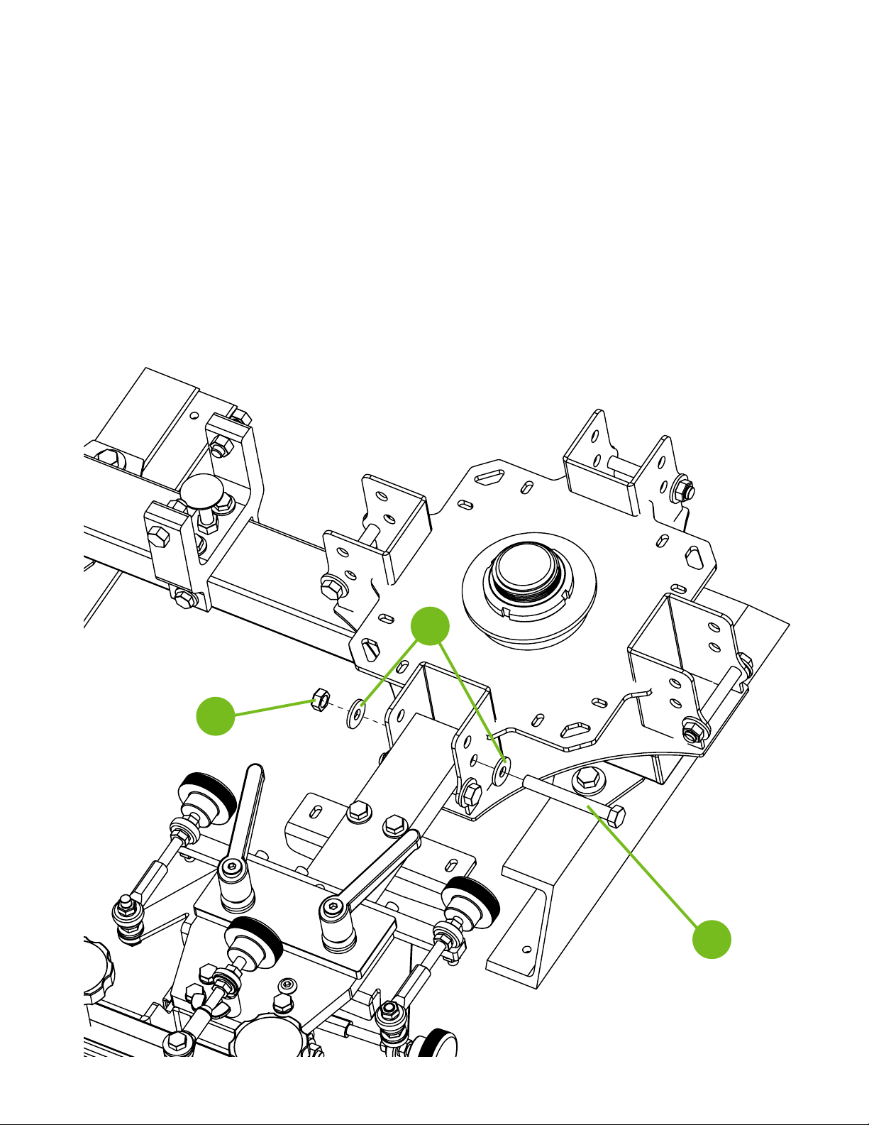
Step 4
Install the upper stop bolts and rubber sleeves. Two 9/16” wrenches
are required for this step. DO NOT OVERTIGHTEN THE BOLTS. This will
cause resistance in the print head hinge point. Repeat this step for the
remaining print head assemblies.
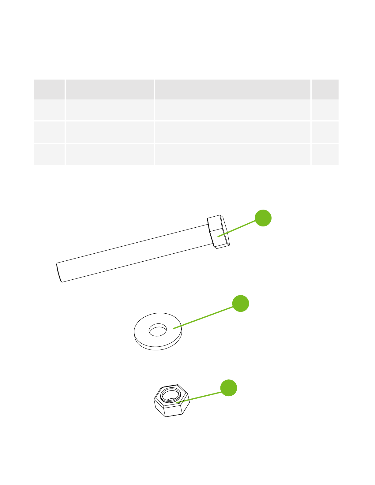
Note: Refer to Page 3 for hardware detail.
1
2
3
1
4
5