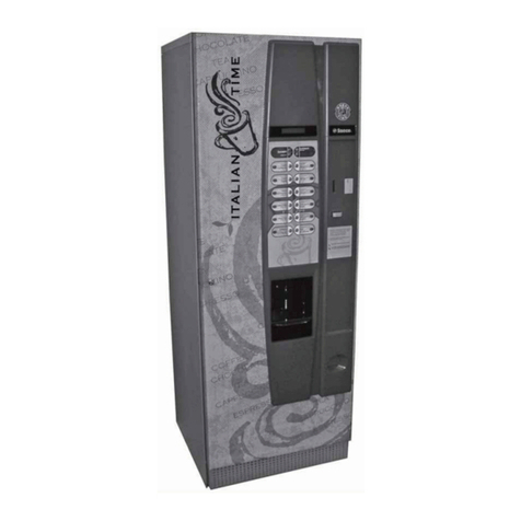
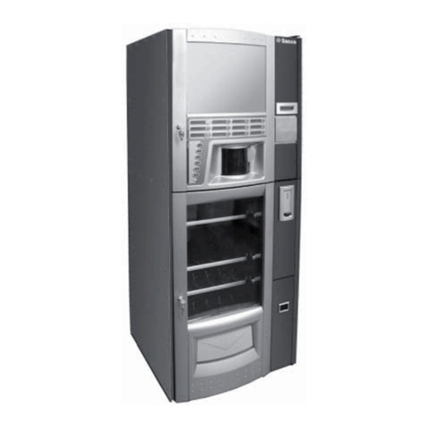
Saeco Group 500 Instructions for use

i
INSTRUCTION AND MAINTENANCE MANUAL
model
Saeco Group 500
Automatic drink vending machine

CONFORMITY DECLARATION i
We:
SAECO International Group
Via Panigali, 39
40041 GAGGIO MONTANO (BO)
hereby declare to our own liability that the following product:
HOT BEVERAGE VENDING MACHINE
TYPE: D.A. G OUP 500
To which the present declaration refers is in compliance with the following norms:
- Machinery safety Fundamental concepts, main design principles.
Terminology, basic methodology EN 292 part 1 September 1991
- Machinery safety Fundamental concepts, main design principles.
Technical specifications and principles EN 292 part 2 September 1991
Electrical household appliance and electrical appliance safety General requirements EN 60335-1 June 1988 +
Amendments 2,5,6,A51
- Electrical household appliance and electrical appliance safety Part 2
Specific requirements of liquid heating appliances
EN 60335-2-15 November 1990
- Electrical household appliance and electrical appliance safety Part 2
Specific requirements for nozzles and coffee grinders
EN 60335-2-33 April 1990
- Electrical household appliance and electrical appliance safety Part 2
Specific requirements for distributors and vending machines
IEC 335-2-75 Document
- Limits and measurement methods of radio disturbance generated by electric and thermal motors for domestic and
related use, electrical instruments and the like
Electrical appliances EN 55014 Ed. 1993
- Electromagnetic compatibility (EMC)
Part 3 Limits Section 2: harmonic current emission limits (appliance input power ± 16A for phase) -
EN 61000-3-2 Ed. 1993
- Electromagnetic compatibility (EMC)
Part 3 Limits Section 3: Limitation of current fluctuations and peaks in low tension power supply systems for
appliances with rated current of ± 16A - EN 61000-3-3 Ed. 1994
- Immunity requirements for household electrical appliances, musical instruments and the like.
Norm for product family EN 55104 Ed. 1995
According to the provisions of the following directives:
CE 73/23 - CE 89/392 - CE 89/336 - CE 91/368
CE 92/31 - CE 93/44 - CE 93/68
The Sole Director: Sergio Zappella
DBEFORE USING THE MACHINE, READ THIS MANUAL CAREFULLY SO AS TO
OPERATE IN ACCORDANCE WITH CURRENT SAFETY STANDARDS.
DATTENTION: Important afety indication
:READ the in truction manual carefully before u ing the machine
The machine mu t be di connected from the main before any ervice or maintenance
may be carried out
EATTENTION: machine witched on
ATTENTION: hot part in contact!

CONTENTS
1 - INTRODUCTION ......................... 4
1.1 User instructions ................................ 4
1.2 General instructions .......................... 4
2 - TECHNICAL SPECIFICATIONS .. 6
3 - GENERAL TECHNICAL
DESCRIPTION ............................... 7
3.1 Machine escription .......................... 7
3.2 Permitte use .................................... 7
3.3 Mo els ............................................... 7
3.4 Basic operating concepts .................. 8
4 - VENDING MACHINE HANDLING 11
4.1 Han ling an transport ...................... 11
4.2 Storage .............................................. 12
4.3 Packaging ......................................... 12
4.4 Receipt .............................................. 12
4.5 Unpacking ......................................... 13
5 - SAFETY STANDARDS ................ 14
6 - INSTALLATION ............................ 15
6.1 Positioning ......................................... 15
6.2 Water mains connection .................... 16
6.3 Electric mains connection .................. 17
6.4 Machine start-up ................................ 18
6.5 Installation ......................................... 19
6.5.1 Cleansing of resin-base water
softener (available as a kit) ................ 19
6.5.2 Water circuit filling ............................. 20
6.5.3 Cleaning the parts in contact
with foo stuffs ................................... 21
6.6 Pro uct loa ing ................................. 22
6.6.1 Container loa ing .............................. 22
6.6.2 Label insertion ................................... 23
6.6.3 Cup loa ing ....................................... 24
6.6.4 Spoon loa ing .................................... 25
6.6.5 Coffee groun s bag insertion............. 26
6.6.6 Payment system installation .............. 27
7 - PROGRAMMING ......................... 28
7.1 Function escription .......................... 32
8 - SERVICE ..................................... 37
9 - MAINTENANCE AND
INACTIVITY ................................. 39
9.1 Cleaning an Loa ing ........................ 39
9.1.1 Daily cleaning .................................... 39
9.1.2 Weekly cleaning ................................ 40
9.1.3 Pro uct loa ing ................................. 41
9.2 Maintenance ...................................... 41
9.2.1 Or inary an extraor inary
maintenance ...................................... 42
9.2.2 Coffee unit maintenance .................... 42
9.3 Settings ............................................. 43
9.3.1 Dosage an grin ing regulation ......... 43
9.4 Resin regeneration (where the
water softener is provi e ) ................ 44
9.5 Inactivity ............................................ 45
10 - DISMANTLING ............................ 46
11- TROUBLESHOOTING GUIDE FOR
THE MOST COMMON FAILURES OR
ERRORS...................................... 47

English
4
1 - INTRODUCTION
1.1 User instructions
Thi vending machine i afe for all tho e who
follow the loading and ordinary cleaning
in truction given in thi manual.
DCaution
For no rea on what oever mu t the operator
acce tho e part of the machine that are
protected by guard requiring pecial
in trument for their removal.
Some maintenance operation (to be carried out
olely by peciali ed technician ) expre ly
require that certain afety device are witched
off.
Acquaintance and ab olute re pect, from a
technical point of view, of the afety tandard
and danger warning contained in thi manual,
are fundamental for in talling, u ing and
ervicing the machine under condition of
minimum ri k.
1.2 General instructions
D :
Before using the vending machine, read this
manual carefully.
Knowledge of the information and
instructions contained in this document is
essential for a correct use of the vending
machine by the user.
Mea ure carried out by the u er on the
automatic vending machine are allowed only
if they are hi re pon ibility and if he ha been
duly trained.
The u er mu t be fully acquainted with all
operating mechani m of the machine a far
a it fall within hi competence.
It i the buyer re pon ibility to a certain that
the u er have been trained and informed of
all the indication and pecification
contained in the documentation upplied.
Even o, the operator or the u er mu t be
aware of the potential ri k that exi t while
operating the automatic vending machine.
Thi manual i an integral part of the
equipment and a a con equence mu t
alway be kept in ide or nearby the machine
o a to allow ea y con ultation by the variou
operator until the machine i di mantled and/
or crapped.
In the event of lo or damage of thi manual,
it i po ible to reque t a new copy from the
manufacturer, indicating the data regi tered
on the machine erial number label.
Operating reliability and the efficiency of the
machine performance are guaranteed only
if original part are u ed.
The u er will be held entirely re pon ible for
any modification he may make to the
machine.
All the operation nece ary in order to
maintain the machine in working order, before
and during u e, are to the charge of the u er.
Tampering with or modification made to the
machine not previou ly authorized by the
manufacturer, relea e the latter from any
liability for damage deriving from, or referable
to the above mentioned modification .
Thi manual reflect the tatu of the
automatic vending machine at the moment
of the i ue on the market; po ible
modification , up-grade or adju tment that
are made to machine that are marketed
ub equently, do not oblige the SAECO
International roup either to intervene on the
machine previou ly upplied or con ider it
and the relevant manual to be defective or
inadequate.
English
5
fig. 1
fig.2
1
However, the SAECO International roup i
entitled, when it deem it expedient for valid
motive , to up-date the manual already
pre ent on the market and end revi ed
information heet to their cu tomer which
mu t kept together with the original manual.
Any technical problem that may ari e can
be olved ea ily by con ulting thi manual.
For further information, contact the dealer
where the machine wa purcha ed, or one
of the authori ed ervice centre .
When calling plea e, give the following
information:
- The data regi tered on the erial number label
(fig.1);
- The ver ion of program re ident in the
microproce or ( ee the adhe ive label on
the component mounted on the C.P.U. card
(ref. 1, fig. 2) or, if po ible, the ver ion of
program hown on the machine di play when
button 2 i pre ed on the CPU card to
activate the Service mode (fig. 42).
- The card code appearing on the welded ide
of the C.P.U. board.
The SAECO International Group decline all
re pon ibility for damage cau ed to per on or
property a a con equence of:
- Incorrect in tallation
- Inappropriate electrical and/or water
connection
- Inadequate cleaning and maintenance
- Unauthori ed modification
- Improper u e of the di tributor
- Non-original pare part
In no event will the SAECO International
roup be obliged to indemnify any damage
cau ed a a re ult of the forced inactivity of
the machine due to failure.
In tallation and maintenance operation mu t
be carried out exclu ively by qualified
engineer .
U e only pecific food tuff for u e in
automatic vending machine .
The automatic vending machine i not
uitable for out ide in tallation. The machine
mu t be in talled in dry location , with
temperature of no lower than 1°C and it mu t
not be in talled in place where cleaning i
done with water ho e (e.g. large kitchen
).
If at the time of in tallation, the u age
condition are different from tho e
e tabli hed or are ubject to change over
time, plea e contact the manufacturer
immediately before u ing the machine.
Furthermore alway act in compliance with
national or local tandard .

English
6
fig.3
2 - TECHNICAL
SPECIFICATIONS
Height mm 1,700
Width mm 590
Depth mm 674
Weight from Kg 90 to Kg 105
Power upply voltage Volt 230
Power Frequency Hz. 50
In talled power KW 1.50
Water main connection 3/8 ga
Electric main connection SCHUCO plug
WATER SUPPLY
From main with pre ure between 0.5 and 6.5
bar
CUP DISPENSER
Suitable for cup with diameter mm 70-71
BOILER RESISTANCES
Armour-plated type:
1000 Watt for coffee boiler
CONTAINER CAPACITY
Coffee in grain Kg 4.0
In tant coffee Kg 1.5
Powdered milk Kg 2.1
Chocolate Kg 4.3
Te a Kg 5 . 9
Soup Kg 5.5
Sugar Kg 5.6
Cup 500
Spoon 500

English
7
fig.4
1
2
5
6
4
3 - GENERAL TECHNICAL
DESCRIPTION
3.1 Machine description
(fig. 4)
ref.1 Coffee unit and grinder
ref.2 Drink di tributor unit
ref.3 Sugar di pen er unit
ref.4 Electronic board
ref.5 Cup di pen er
ref.6 Coin box unit
3.2 Permitted use
The di tributor i to be u ed exclu ively for the
di pen ing of drink , prepared mixing food tuff
with water (by infu ion a far a coffee i
concerned).
For thi purpo e, u e product that the
manufacturer ha declared uitable for the
automatic di tribution in open container .
The drink are di pen ed into pecific pla tic
cup automatically di tributed by the machine.
The ugar tirring poon i di pen ed
automatically.
The drink mu t be con umed immediately and
under no circum tance mu t they be kept for
ub equent con umption.
3.3 Models
The following terminology i u ed o a to
di tingui h the variou model of automatic
di tributor :
SAECO GROUP 500 Standard
Ver ion with pla tic coffee unit and 3 in tant
product
SAECO GROUP 500 FREEZE DRIED
Ver ion with pla tic coffee unit and freeze dried
coffee drink in tead of freeze dried tea
DAttention
This manual refers to the top-of-the -range
model:
it is therefore possible to find descriptions or
explanations not relating to your machine.

English
8
fig.5
fig.6
fig.7
fig.8
3.4 Basic operating concepts
During normal functioning, the di tributor i in
tandby tatu . By introducing the nece ary
amount, according to the pre- et price, and
pre ing the key relating to the de ired drink,
the drink di pen ing cycle i activated: It can be
divided in different proce e :
CUP DISPENSING
Thi i the fir t operation that the di tributor
activate (except for without CUP
di pen ing).
The motor that operate the nozzle upport
i activated in order to move the upport back
and let the cup drop into the delivery
receptacle. (fig. 5).
The motor in ide the cup di pen er move
the croll in order to eparate and make the
cup fall into the pecial upport fork in ide
the delivery receptacle (fig.6).
SUGAR AND SPOON DISPENSING
Where anticipated and reque ted, a maximum
et amount of ugar i di pen ed with the
po ibility to top when the de ired do e ha
been achieved.
The di pen ing procedure occur according to
the following tage :
The drive motor of the chute which convey
the ugar into the cup i activated (fig.8).
The gear motor activate the helicoidal crew
conveyor of the ugar container, di pen ing
the de ired quantity into the product chute
(fig.7).

English
9
fig.10
fig.9
fig.11
The electromagnet that control the poon i
engaged and the poon i delivered directly
into the cup through the appropriate chute
(fig.9).
INSTANT DRINKS
Thi proce i activated after the proce ing
of cup, ugar and poon di pen ing ha been
completed.
According to the drink type reque ted and
di tributor model, the proce e de cribed
below are activated for the preparation of the
drink.
If pre ent, the motor-mixer i activated
(fig.10).
The olenoid valve for in tant drink , fixed to
the coffee boiler, i engaged in order to deliver
the required quantity of water into the mixer
(fig.11); the pump that deliver the required
amount of water - controlled by a pecial
electronic device (volumetric counter)- tart
up.

English
10
fig.14
fig.12
fig.13
fig.16
fig.15
The in tant product gear motor activate the
helicoidal crew conveyor o a to di pen e
the programmed quantity of product into the
mixer (fig.12).
Once the pre- et quantity of water and
powder i di pen ed, the motor-mixer i
witched off.
ESPRESSO COFFEE
Thi proce occur after di pen ing cup, ugar
and poon.
The grinder i activated until it produce the
do e of ground coffee et by the do er
(fig.13).
The do er electromagnet i activated,
cau ing the opening of the door and the
con equent drop of the coffee into the brew
chamber (fig.14).
The rotation unit gear motor tart -up, bring
it into the di pen ing po ition and
imultaneou ly compre e the ground
coffee (fig.15).
The pump that deliver the required amount
of water -controlled by a pecial electronic
device (volumetric counter)- tart up,
withdrawing the water from the coffee boiler
(fig.16).

English
11
fig.17
fig.18
The coffee unit gear motor i activated again
o a to return to the tandby po ition; during
thi movement the coffee ground are
expelled (fig.17).
The activation equence of grinder and coffee
do er can be inverted depending on the pre- et
programming type ( ee programming menu).
4 - VENDING MACHINE
HANDLING
4.1 Handling and transport
(fig. 18)
The tran port of the di tributor mu t be carried
out by competent per onnel.
The di tributor i delivered on a pallet; for
handling purpo e u e a pallet truck and move
it lowly in order to avoid cap izing or dangerou
movement .

English
12
fig.19
FAttention
Avoid :
- lifting the di tributor with rope or pre e
- dragging the di tributor
- turning over or laying the di tributor down
during tran port;
- jolting the di tributor
With regard to the di tributor, avoid :
- bumping it
- overloading it with other package
- expo ing it to rain, freezing weather or
ource of heat
- keeping it in damp place
4.2 Storage
In the event of torage, avoid placing everal
machine one on top of another, maintain it in a
vertical po ition, in dry place with temperature
of no lower than 1° C.
4. Packaging
The di tributor i protected by poly tyrene
angle and by a tran parent polypropylene film
(fig.19).
The automatic di tributor will be delivered
packaged, a uring both a mechanical guard
and protection again t damage from the out ide
environment.
Label are applied on the packaging, indicating:
- handle with care;
- do not turn up ide-down;
- protect from the rain;
- do not place one on top of another;
- protect from ource of heat;
- not bump re i tant;
- type of di tributor and erial number.
4.4 Receipt
Upon receipt of the automatic di tributor, it i
nece ary to check it ha not uffered damage
during tran port. If damage of any kind i
noticed, place a claim with the forwarder
immediately.
FAttention
On conclusion of transport, the packaging
must be integral which means it must not:
- pre ent dent , ign of bump , di tortion or
breakage to the external packaging;
- pre ent wet zone or ign that could lead
one to uppo e that the packaging ha been
expo ed to rain, freezing weather or heat;
- pre ent ign of tampering.

English
1
fig.20
fig.21
fig.23
fig.22
4.5 Unpacking
- Free the di tributor from the packaging,
cutting the protective film in which it i
wrapped, along one of the protection angle
(fig.20).
Remove the di tributor from the tran port pallet,
un crewing the crew that ecure it to the pallet
(fig.21).
- Remove the key from the drink di pen er
receptacle (fig.22).
Open the door of the di tributor and remove the
adhe ive tape from the component , li ted
below:
cup di pen er (example in fig.23)
coin box
coffee unit, coffee chute
poon di pen er counter-weight
product container
liquid wa te float mechani m
bottom kirting-board
liquid wa te bin.

English
14
fig.24
- remove the poly tyrene that block the
product container (fig.24)
DCaution
The packing material must not be left
accessible to others, as it is a potential source
of danger. For the disposal contact qualified
companies.
5 - SAFETY STANDARDS
D :
- Before u ing the automatic di tributor, read
thi manual carefully.
- The in tallation and maintenance operation
mu t be performed exclu ively by qualified
technical per onnel.
- For no rea on what oever mu t the operator
acce tho e part of the machine that are
protected by guard requiring pecial
in trument for their removal.
- Acquaintance and ab olute re pect, from a
technical point of view, of the afety tandard
and danger warning contained in thi
manual, are fundamental for in talling, u ing
and ervicing the machine in condition of
minimum ri k.
Alway di connect the POWER CABLE before
maintenance or cleaning activitie .
Do not, under any circum tance , intervene on
the machine or remove afety guard before hot
part have cooled!
- Operating reliability and the efficiency of the
machine performance are guaranteed only
if original part are u ed.
- The automatic vending machine i not
uitable for out ide in tallation. The machine
mu t be in talled in dry location , with
temperature of no lower than 1°C and it mu t
not be in talled in place where cleaning i
done with water ho e (e.g. large kitchen
).
- In order to guarantee regular functioning,
alway maintain the automatic di tributor
under perfect cleaning condition .

English
15
fig.25
- the SAECO International roup decline all
re pon ibility for damage cau ed to per on
or property a a con equence of:
Incorrect in tallation
Inappropriate electrical and/or water
connection
Inadequate cleaning and maintenance
Unauthori ed modification
Improper u e of the di tributor
Non-original pare part
- Furthermore you are advi ed to alway act
in compliance with national or local tandard .
6 - INSTALLATION
.1 Positioning
The automatic vending machine i not uitable
for out ide in tallation. The machine mu t be
in talled in dry location , with temperature of
no lower than 1°C ; furthermore, it mu t not be
in talled in place where cleaning i done with
water ho e or in place were there i danger
of explo ion or fire .
- If po itioned near a wall, there mu t be a
minimum di tance from the wall of at lea t 5
cm. (fig.25) o a to allow regular ventilation.
Under no circum tance cover the di tributor
with cloth or imilar.

English
16
fig.26
fig.27
fig.28
- Po ition the di tributor, checking the levelling
by mean of the adju table feet already
a embled on the machine (fig.26). Make
ure that the di tributor doe not have an
inclination of more than 2 degree .
The SAECO International roup decline all
re pon ibility for inconvenience cau ed a a
re ult of the failure to ob erve the above
mentioned in tallation norm .
If in tallation take place in afety evacuation
corridor , make ure that the di tributor with the
door open leave ufficient pace for individual
to pa by (fig.25).
In order to avoid dirtying the floor a a re ult of
the accidental pillage of product , u e, if
nece ary, a protective matting ufficiently wide
to cover the operating area under the di tributor.
.2 Water mains connection
Before connecting the di tributor to the water
main make ure that the water :
- i drinkable (if nece ary by mean of te t
laboratory certification);
- ha a pre ure ranging between 0.5 bar and
6.5 bar (otherwi e u e a pump or a water
pre ure reducer accordingly);
- if not already pre ent, in tall a tap in an
acce ible po ition o a to eparate the
apparatu from the water main hould it be
nece ary (fig.27);
- let ome water flow out of the tap o a to
eliminate po ible trace of impuritie and dirt
(fig.28);

English
17
fig.29
fig.30 fig.31
- connect the tap to the di tributor, u ing a rigid
copper or nylon pipe, uitable for food tuff
and adequate for the purpo e of bearing the
water upply pre ure. Should a flexible pipe
be u ed, it i nece ary to a emble the
reinforcement bearing in ide, which come
upplied with the machine (fig.29);
- the anticipated connection i a 3/8 ga
(Fig.30).
.3 Electric Mains connection
The di tributor i de igned to operate with
monopha e 230 Volt voltage and i protected
by 10A and 16A fu e .
We ugge t that you hould check the following:
- the main voltage of 230 V mu t not have a
difference of more than ± 6%;
- the power upply mu t be adequate to bear
the load of the machine;
- u e a diver ified protection y tem.
The machine mu t be earthed in ob ervance
with operating afety norm .
For thi rea on, verify the y tem earth wire
connection to a certain that it i efficient and in
compliance with national and European electric
afety tandard .
If nece ary, reque t the intervention of qualified
per onnel for the verification of the plant.
- The di tributor i equipped with a power
upply cable H05VV-F 3x1.5 mm2, with a
SCHUCO plug (fig.31).

English
18
fig.32
fig.33
fig.34
fig.35
- The ocket that are not compatible with the
plug of the machine mu t be replaced.
- The u e of exten ion , adapter and/or
multiple plug i forbidden (fig.32).
The SAECO International roup decline all
re pon ibility for damage due to the non
ob ervance of the afore aid norm .
.4 Machine start-up
The di tributor i equipped with a afety witch
(fig.33) which di connect the power upply to
the machine whenever the door i opened ( ee
electrical layout).
In ca e of nece ity, therefore, open the door
or unplug the in tallation.
DCaution
During the setting-up phase, before powering
up the machine, make sure you have
connected it to the hydraulic system and
opened the water tap.
DCaution
The power cable plug (ref.1, fig.34) as well
as the service switch inside the distributor
(ref.1, fig. 35) remain live.
- It i however nece ary to operate with the
door open but the di tributor connected to
the main for ome operation .

English
19
fig.36
fig.37
fig.38
Competent technician only may operate in thi
manner, by in erting the pecial pla tic key,
upplied with the di tributor, into the door witch,
turning it 90° (fig.36).
DCaution
The opening and eventual activation of the
distributor with the door open (for cleaning
purposes only) must only be performed by
authorized and technically qualified
personnel. Do not leave the distributor
unattended while it is open.
Give the key to qualified per onnel only.
Each time the di tributor i witched on a
diagno i cycle i performed in order to verify
the correct po ition of the moving part and the
pre ence of water and other product .
.5 Installation
FImportant
When switched on, the machine
automatically proceeds to fill the water circuit
and the related boilers. For a correct
automatic installation in the event of using a
water softener system, it is necessary that
the latter is completely filled with water and
opportunely relieved of any air bubbles
.5.1 Cleansing and filling of resin-
based water softener
Before in talling the water oftener in the
machine and u ing it, it i advi able to clean e
the re in and fill the water oftener. Therefore,
install the water softener already filled with water
and cleansed. If you wi h to carry out thi
operation directly in the machine, act a follow :
- In ert the pipe of the bottom tap in a container
uitable for thi u e.
- open the bottom tap (fig.37).and the upper
tap of the water oftener o a to remove the
air bubble.
- in ert the key in the door witch (fig.38).
- let the water oftener fill up completely and
remove the key from the door witch.
- clo e the upper tap.
- in ert the key once again in the door witch.

English
20
fig.39
fig.40
- let the water flow out of the wa te pipe until it
i clear (fig.39).
- remove the key and clo e the tap.
.5.2 Water circuit filling
The machine proceed to fill the in tant product
boiler fir t, if pre ent, and the water chamber;
ub equently it fill the e pre o coffee boiler
automatically activating two continual vend of
long coffee.
FImportant
Before switching the machine power on and
thus proceeding with the automatic
installation:
1. En ure that the water oftener i filled with
water and the air bubble removed.
2. Load the coffee grain into the appropriate
container; thi operation i nece ary o that
the machine automatically di pen e coffee
for the purpo e of filling the boiler.
3. Load at lea t the central column of the cup
container.
NOTE:
If the filling of the boiler i not ucce ful, the
machine will not make it elf available for ervice
and will indicate in tallation failed on the di play
panel; in uch an event, eliminate the defect and
repeat the automatic in tallation, after having re-
et the fault (Section 8 SERVICE, failure
re et).
After the DIAGNOSTIC tage the machine
automatically fill the hydraulic circuit of the
chamber with water float of the in tant drink
boiler and of the boiler for the coffee unit. During
thi tage, the heating re i tance of the boiler
remain automatically off. If the machine detect
that the boiler i loaded, it automatically pa e
to the HEATING tage.
The equence of operation will be:
- in ert the pecial key in the door witch;
- on tart-up of the machine, the water
chamber with float automatically tart to fill
up, while the machine carrie out the
automatic diagno i tage.
FImportant
Compress the tube which connects the boiler to
the water chamber several times; keep on doing
so until the air bubbles which may have formed
have been eliminated (fig.40).
- During the diagno i , the following part are
activated equentially:
- the coffee unit in order to perform a correct
tart po itioning;
- then the cup di pen er in order to perform
the loading of the fir t column of cup in the
relea e device.
During the ub equent initiali ation tage:
- the in tant drink boiler, if pre ent, and water
chamber fill up;
- 2 complete vend of extremely long coffee
are performed automatically for the purpo e
of filling the boiler of the coffee unit.
Table of contents
Other Saeco Vending Machine manuals

Saeco
Saeco DA 7P Plus User manual

Saeco
Saeco SAECO D.A. 10P Plus Guide

Saeco
Saeco ATLANTE User guide

Saeco
Saeco D.A. CRISTALLO 400 User guide

Saeco
Saeco BP 56 User guide

Saeco
Saeco D.A. 8P Standard Installation guide

Saeco
Saeco CRISTALLO 600 User guide

Saeco
Saeco BOX MONETIERA User manual

Saeco
Saeco ROYAL OFFICE SUP 015V Installation guide

Saeco
Saeco D.A. COMBISNACK User guide
Popular Vending Machine manuals by other brands

Elektral
Elektral TRU-VEND Maxi-Buffet Instructions for use & maintenance manual

Bianchi
Bianchi REPARTO CORSE SADDLE Use and maintenance manual

NCR
NCR 7800 user guide

Necta
Necta Snakky manual

N&W Global Vending
N&W Global Vending Canto Plus Instant Installation operation & maintenance

Fastcorp
Fastcorp DIVI Setup and user guide