7
Italiano
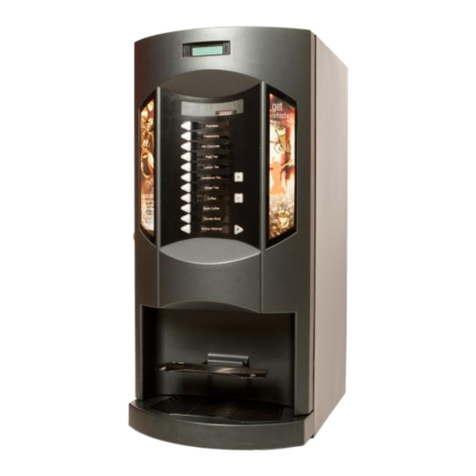
Fig.1
Fig.2
620
640
1830
123
•
••
measurements in millimeters
4
•
1.3 Machine identification
Technical specifications
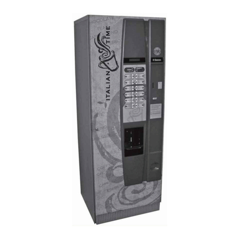
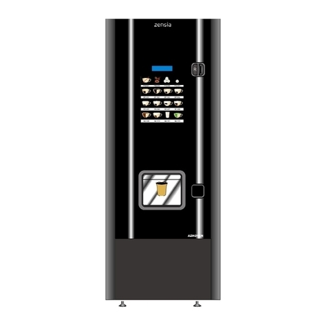
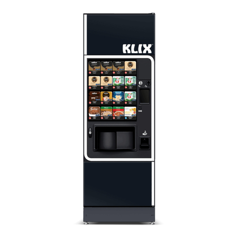
Dimensions......................................................................... See Figure 1
Machine weight ..........................................................................114 kg
Power consumption .......................... See rating plate on back of machine
Voltage ........................................... See rating plate on back of machine
Power cord length ...................................................................... 200 cm
Water supply.................. compressed pressure 0,1 - 0,6 MPa (1 - 6 bar)
Capacities
Coffee beans ..................................................................................4 kg
Soluble coffee ..............................................................................1.5 kg
Soluble milk.................................................................................2.1 kg
Soluble products .....................................................................4 - 4.5 kg
Sugar ............................................................................................4 kg
Stir sticks ........................................................................................ 480
Cups .............................................................................................. 500
Drain tank ........................................................................................ 9 l
NOTE: The abovementioned quantities are subject to
variations depending on the brand and type of
product used.
Position of rating plate
The identification plate ref.1and rating plate ref. 2can be found on the
back of the machine (Fig. 2).
• On the interior right side of the machine’s housing (near the bean hop-
per) you will find a plate with the serial number of the machine. The se-
rial number also appears on the identification plate ref. 1(Fig. 2). Do not
remove or damage these plates, as they contain information about the
machine, allowing the Manufacturer to easily and quickly identify the
machine. The identification plate also states the required power and vol-
tage values for correct and safe machine operation.
Operator’s instructions
• The Manufacturer of the machine is at the purchaser’s disposal for any further information he/she may need regarding
the correct and safe operation of this machine.
• Please contact your local representative or the Manufacturer directly should problems arise beyond the scope of this ma-
nual.
• The Manufacturer reserves the right to make modifications to the machine without prior notice.
• The descriptions and illustrations contained in this manual are not binding.
• The Manufacturer reserves all rights to reproduction of this manual both in its entirety and in parts.
☞
