manuals.online logo
Brands
  1. Home
  2. •
  3. Brands
  4. •
  5. Safe Fleet
  6. •
  7. Automobile Electronic
  8. •
  9. Safe Fleet RVS-218628 User manual

Safe Fleet RVS-218628 User manual

Reverse With Condence ™ 1
G-SERIES Backup Camera System with
Auto Dimming, Compass and Temperature
RVS-218628
Instruction Manual
RVS Systems, Inc. © 2017
RVS Systems Reverse With Condence ™
2 3
NOTE! Please read all of the installation instructions
carefully before installing the product. Improper
installation will void manufacturer’s warranty.
Congratulations on purchasing a RearView Backup
Camera System!
With this manual you will be able to properly install and
operate the unit.
The Backup Camera System is intended to be installed as a
supplement aid to your standard rear view mirror that already exists
in your vehicle. The Backup Camera System should not be used as a
substitute for the standard rear view mirror or for any other mirror
that exists in your vehicle.
In some jurisdictions, it is unlawful for a person to drive a
motor vehicle equipped with aTV viewer or screen located forward of
the back of the driver’s seat or in any location that is visible, directly
or indirectly, to the driver while operating the vehicle.
TABLE OF CONTENTS
INTRODUCTION
Introduction...............................03
SafetyInformation..........................04-06
Before Beginning Installation. . . . . . . . . . . . . . . . . . . . . . . 07
InstallationGuide.......................... 08-09
AdjustableGridLine...........................10
InstallationandWire.........................11-13
DigitalCompassCalibration......................14-15
TemperatureSetting...........................16
Magnetic Fluxline Distribution. . . . . . . . . . . . . . . . . . . 17-19
MonitorSpecications .........................20
CameraSpecication..........................21
CameraInstallation...........................22
Troubleshooting.............................23
Warranty&Disclaimer........................ 24-25
RVS Systems Reverse With Condence ™
4 5
Please read the entire manual and follow the instructions and
warnings carefully. Failure to do so can cause serious damage and/or
injury, including loss of life. Be sure to obey all applicable local
trac and motor vehicle regulations as it pertains to this product.
Improper installation will void manufacturer’s warranty.
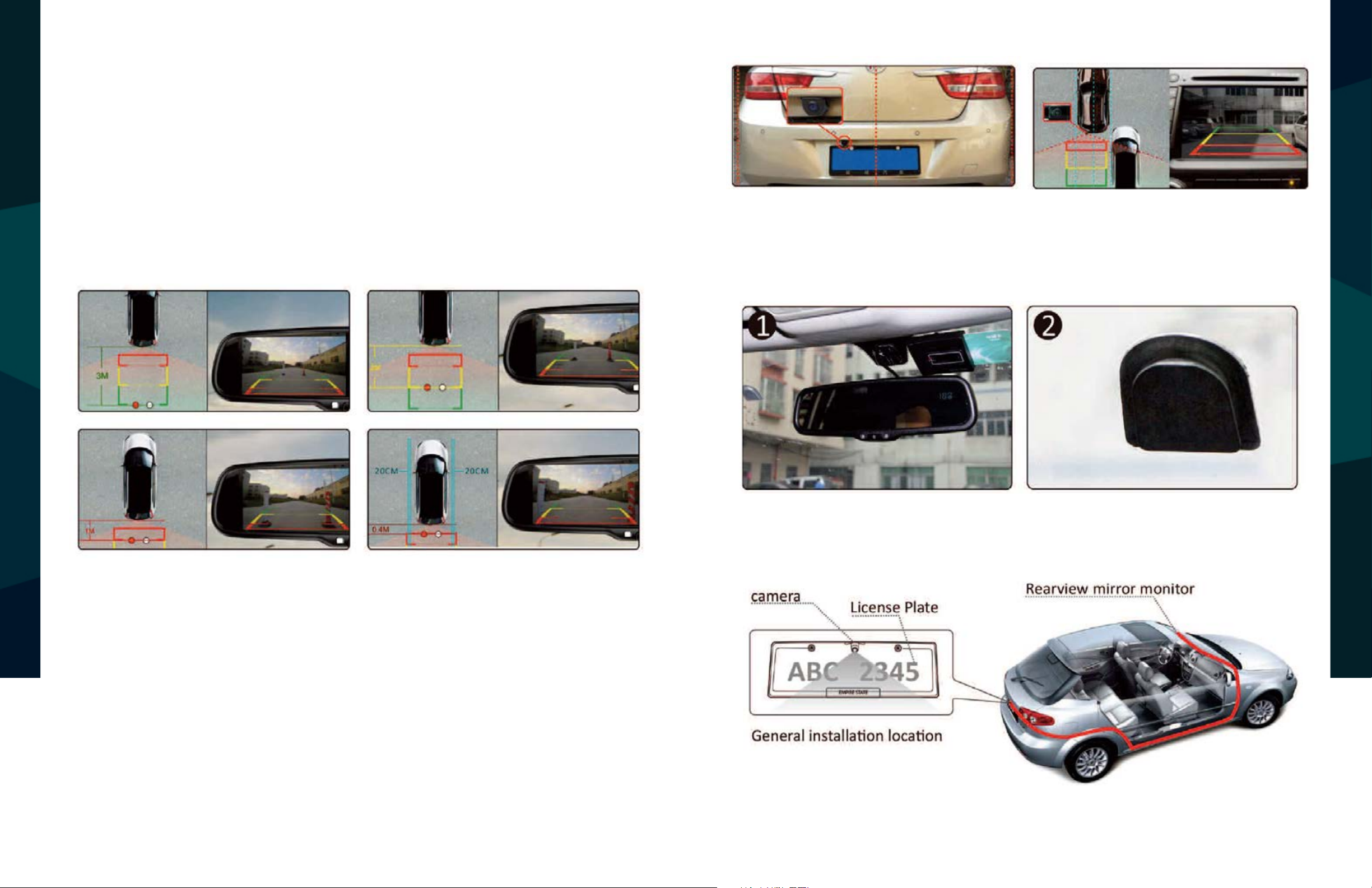
• The Rear View Camera System is
designed to help the driver safe-
ly detect people and/or objects
helping to avoid damage or injury.
However, you the driver, must use it
properly. Use of this system is not a
substitute for safe, proper or legal
driving.
• Never back up while looking at the
monitor alone. You should always
check behind and around the vehi-
cle when backing up, in the same
way as you would if the vehicle did
not have the Rear View Camera
System.Ifyoubackupwhilelooking
only at the monitor, you may cause
damage or injury. Always back up
slowly.
•The Rear View Camera System is
not intended for use during exten-
sive back-up maneuvers or backing
into cross trac or pedestrian walk-
ways.
•Please, always remember, the area
displayed by the Rear View Camera
Systemis limited.Itdoes notdisplay
the entire panorama that is behind
you.
USAGE:
•Electric shock or product
malfunction may occur if this
product is installed
incorrectly.
• Use this product within
the voltage range specied. Failure
to do so can cause
electronic shock or product
malfunction.
• Take special care when
cleaning the monitor.
•Make sure to rmly ax the prod-
uct before use.
• If smoke or a burning smell
is detected, disconnect the
system immediately.
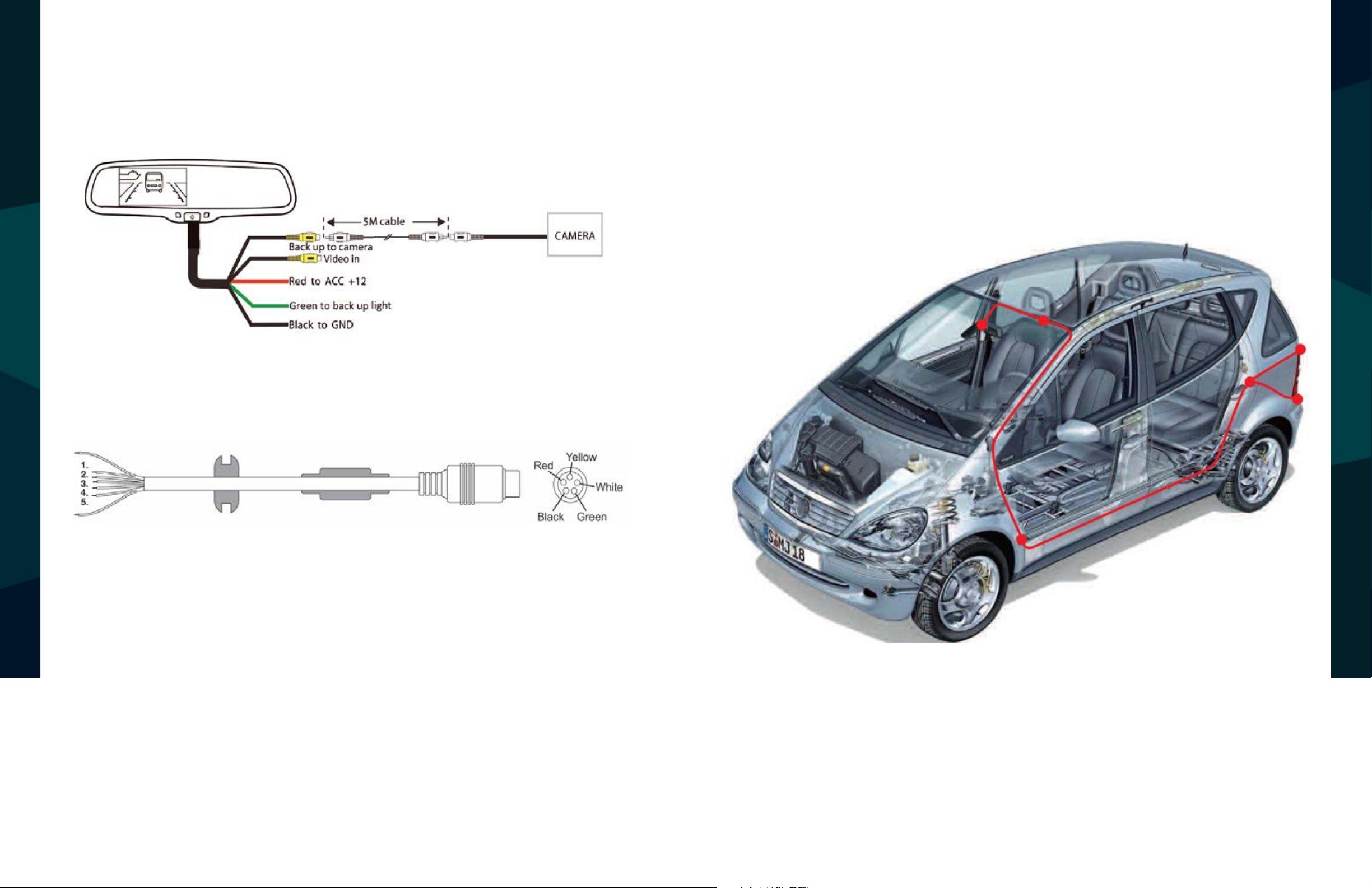
•Where the power cable may touch
a metal case, cover the cable with
friction tape. A short circuit
or disconnected wire may cause a
re.
• While installing the Rear View
System be careful with the wire
positioning in order to avoid wire
damage.
• The Rear View System should only
be used when the vehicle is in
reverse.
• Do not watch movies or
operate the monitor while driving;
as it may cause an
accident.
• Do not install the monitor
where it may obstruct drivers
view or obstruct an air bag
device.
• Dropping the unit may cause
possible mechanical failure.
INSTALLATION:
SAFETY INFORMATION
SAFETY INFORMATION
RVS Systems Reverse With Condence ™
6 7
If you have questions about this product, contact:
RVS Systems
1797 Atlantic Avenue
Brooklyn, NY 11233
Tel: 1.800.764.1028
IN NO EVENT SHALL SELLER OR MANUFACTURER BE
LIABLE FOR ANY DIRECT OR CONSEQUENTIAL DAMAGES OF
ANY NATURE, OR LOSSES OR EXPENSES RESULTING FROM
ANY DEFECTIVE PRODUCT OR THE USE OF ANY PRODUCT.
Before drilling please check that no cable or wiring is on the other side
of the wall. Please clamp all wires securely to reduce the possibility
of them being damaged while vehicle is in use. Keep all cables away
from hot or moving parts and electrical noisy components.
We recommend doing a benchmark test before installation
to insure that all components are working properly.
Step 1: Choose the monitor and camera locations.
Step 2: Install all cables in vehicle, when necessary a 0.8 (20mm)
hole should be drilled for passing camera cable through vehicles
walls. Install split grommets where applicable.
Step 3: Once all cables and wiring have been properly routed, perform
a system function test by temporarily connecting the system. If the
system seems to not be operating properly see troubleshooting (page
23).
SAFETY INFORMATION
BEFORE YOU BEGIN
RVS Systems Reverse With Condence ™
8 9
Replacement Monitor
The mirror monitor replaces the existing car mirror. Carefully remove
the mirror o the“pin”. Slide the replacement mirror on to the pin and
secure it with the screw provided (already in the screw hole).Dier-
ent cars have dierent brackets, depending on your vehicle make and
manufacturer. There are many methods to remove the original rear-
view mirror, however, please don’t force the mirror o the bracket.
The manufacturer will not be responsible for damage caused to your
car by wrong installation of the mirror. Figure 1.1
Clip-On Monitor
1. The Mirror Monitor attaches to the existing rear view mirror in
vehicle with the pressurized clips on the back of the monitor.
2. Attach monitor to existing mirror, and adjust mounting angle to
allow optimum driver viewing comfort.
Camera & Cable
Be sure to position the cable properly. The aviation camera cable uses
aircraft grade connectors which means the camera cable can be ex-
posed to all weather elements. Do not run the cable over sharp edges,
do not kink the cable and keep away from HOT and rotating parts.
Fasten all cables and secure all excess cable. Connect camera to the
camera extension cable which runs inside the vehicle. Figure 1.2
Wiring
After connecting the camera to the“camera cable”the camera should
be plugged into AV2 input. Connect the RED 12V power wire to an igni-
tion power source and the BLACK 12V ground wire to a chassis ground.
The GREEN wire is the REVERSE trigger wire. Connect this wire to the
vehicle’s backup light circuit to activate the rear-view image whenever
the vehicle shifts into reverse. To connect a second camera, connect it
to AV1 input. It can be turned on by pressing the power button on the
monitor. Figure 2.1, Figure 2.2
Precautions for use of Mirror Monitor
I. The Mirror Monitor is made of glass. Do not subject it to a
mechanical shock by dropping it from a high place, etc.
II. Do not apply excessive force to the monitor surface or the
adjoining areas since this may cause the color tone to vary.
III. Clean with a soft dry cloth and/or Windex only.
IV. Do not attempt to disassemble the mirror monitor.
Safety
• Before drilling, be sure no cable or wire is on the other side.
• Feed as much cable as possible into vehicle & clamp securely.
This reduces the possibility of cable being hooked or snagged.
INSTALLATION GUIDE
INSTALLATION GUIDE + TIPS
RVS Systems Reverse With Condence ™
10 11
Generally, to help drivers estimate the distance from obstacles, there are
three lines for reference- red, yellow, and green. Those three lines are dis-
played on the monitor when car is reversing.The green line is 3M from the
back of the car and the yellow line is 6.5 ft. The distant red line is 1M from
the backside of car while the close red line is 0.4M. Both reference lines on
the left and right should leave 0.2M space from the car.
The accuracy of the grid-lines can vary based on how you angle your cam-
era. Therefore to compensate for inaccurancies, you can adjust the grid-
lines to your camera angle.
FIGURE 1.1
FIGURE 1.2
ADJUSTABLE GRID LINE
INSTALLATION AND WIRE
Accuracy
Grid Lines
RVS Systems Reverse With Condence ™
12 13
1. RED- Power (+)
2. YELLOW- Video
3. GREEN- Mirror / Normal Imaging
4. WHITE- Audio
5. BLACK- Ground (-)
HOW TO WIRE + SPLICING
FIGURE 2.2
FIGURE 2.1
RVS Systems Reverse With Condence ™
14 15
DIGITAL COMPASS CALIBRATION
Digital Compass Calibration
Caution
The compass can be calibrated by driving your vehicle in several complete circles. See
gures below. If the vehicle’s compass headings become inaccurate, the compass
can also be manually calibrated:
1.Press the “MENU” three times to enter into the“SETTING”menu, and press“SEL/REC”to
choose“ANGLE”. Scroll UP/DOWN to adjust the angle.
Please visit: http://magnetic-declination.com/ to nd out the compass angle
of your area. (5-1)
2. Use ”SEL/REC”to select“CALIBRATION”, the default mode is“OFF”, press“DOWN”and
select“AUTO”(1-2)
3. Drive your vehicle in at least 2 circles counterclockwise, allowing 90 seconds
to complete one circle.
4. Keep your circle radius close to 5 meters and your speed less
than 10km/h for the most accurate calibration. (1-3)
1. Make sure the rear view mirror is clearly visable to the driver before calibration.
2. Do not calibrate the compass near a large truck.
3. Make sure that you drive in several complete circles, the steering wheel needs to reach a cer-
tain angle for calibration to function properly. The diameter of the driving circle should be close
to 5 meters.
4. Do not drive too fast when calibrating, your pace should be equal to one third normal adult
walking speed. Complete 2-3 circles to nish the calibration.
5. After a new car audio system is installed, the compass needs to be recalibrated. This is be-
cause the car’s magnetic eld has changed.
5. Use“SEL/REC” to select“CALIBRATION”, use UP/DOWN to select“OFF”(1-4)
DIGITAL COMPASS CALIBRATION
RVS Systems Reverse With Condence ™
16 17
TEMPERATURE SETTING
Q&A
Temperature Setting (Option)
Temperature Sensor Installation
The Distribution Of Magnetic Fluxline
Q: Why does the compass need to be calibrated?
A: The magnetism of a car is stronger than the magnetism of the Earth. The compass will only
function properly if it is calibrated to the magnetic conditions of Earth.
Q: Why is the compass not accurate in some areas?
A: In some areas, such as iron mines, high-intensity magnetic elds change the Earth’s
magnetism.
Q: Why are old cars more dicult to calibrate than new cars?
A: The older a car is, the more magnetized it will be. More magnetized cars are more dicult
to calibrate and may still have problems after calibration.
Press“MENU”to enter into“SETTING”menu, and press“SEL/REC”button to choose“TEMP
UNIT”. Toggle UP/DOWN to switch between °F and °C. (4-1)
Locate the temperature sensor between the front of the radiator and the front
bumper. Slide the metal clip over the edge of the sheet metal or plasic shield until it is secure.
Do not install the temperature sensor near the engine.
We do not recommend using the compass in an area with high magnetic
lines of ux. For example, in the north of Canada.
MAGNETIC FLUXLINE DISTRIBUTION
RVS Systems Reverse With Condence ™
18 19
MAGNETIC FLUXLINE DISTRIBUTION
RVS Systems Reverse With Condence ™
20 21
10.25”
3”
About Our Monitor
SPECIFICATIONS:
MONITOR SPECIFICATIONS
Screen Size:
Display Screen:
Display Resolution:
Aspect Ratio:
Color Depth:
Pixel Pitch (mm)
Power Consumption:
Working Voltage:
Video Input:
Signal System:
4.3”
TFT-LCD
400(H)x234(V)
16:9
16.7M dithering
0.219x0.219
8W
DC 9V-32V
VIDEO-IN to GPS/DVD
(Default) Camera to backup camera
PAL/Auto/NTSC
CAMERA SPECIFICATIONS
About Camera
SPECIFICATIONS:
RVS Systems Reverse With Condence ™
22 23
CAMERA INSTALLATION
Camera Installation
position
170º
viewangle
installation
Mounting Position
• Do a hard reset, unplug all cables
and power cables, leave out for 1
minute and then re-connect them
• Check to ensure that the
connection to the camera is tight
•Verify camera cable is plugged into
port labeled Backup Camera
•Verify that the green positive
trigger on power harness is put to
power 12v+
•Verify camera is on correct camera
input
•Verify cable is connected to
monitor
•Verify camera is connected to
cable
• Connect known working camera
and cable to monitor
•Verify Green trigger is receiving
power
No Image On Screen
TROUBLESHOOTING
RVS Systems Reverse With Condence ™
24 25
ONE YEAR WARRANTY
RVS SYSTEMS, INC. WARRANTS THIS PRODUCT AGAINST MATERIAL DEFECTS FOR A PERIOD
OF ONE YEAR FROM DATE OF PURCHASE. WE RESERVE THE RIGHT TO REPAIR OR REPLACE
ANY SUCH DEFECTIVE UNIT AT OUR SOLE DISCRETION. RVS SYSTEMS, INC. IS NOT RESPON
SIBLE FOR A DEFECT IN THE SYSTEM AS A RESULT OF MISUSE, IMPROPER INSTALLATION,
DAMAGE OR MISHANDLING OF THE ELECTRONIC COMPONENTS. RVS SYSTEMS, INC. IS NOT
RESPONSIBLE FOR CONSEQUENTIAL DAMAGES OF ANY KIND.
THIS WARRANTY IS VOID IF: DEFECTS IN MATERIALS OR WORKMANSHIP OR DAMAGES
RESULT FROM REPAIRS OR ALTERATIONS WHICH HAVE BEEN MADE OR ATTEMPTED BY
OTHERS OR THE UNAUTHORIZED USE OF NONCONFORMING PARTS; THE DAMAGE IS DUE
TO NORMAL WEAR AND TEAR, THIS DAMAGE IS DUE TO ABUSE, IMPROPER MAINTENANCE,
NEGLECT OR ACCIDENT; OR THE DAMAGE IS DUE TO USE OF THE RVS SYSTEMS, INC. SYSTEM
AFTER PARTIAL FAILURE OR USE WITH IMPROPER ACCESSORIES.
WARRANTY PERFORMANCE
DURING THE ABOVE WARRANTY PERIOD, SHOULD YOUR RVS SYSTEMS PRODUCT
EXHIBIT A DEFECT IN MATERIAL ORWORKMANSHIP, SUCH DEFECTWILL BE REPAIRED WHEN
THE COMPLETE RVS SYSTEMS, INC. PRODUCT IS RETURNED, POSTAGE PREPAID AND IN
SURED,TO RVS SYSTEMS, INC. OTHERTHANTHE POSTAGE AND INSURANCE
REQUIREMENT, NO CHARGE WILL BE MADE FOR REPAIRS COVERED BY THISWARRANTY.
WARRANTY DISCLAIMERS
NOWARRANTY, ORAL ORWRITTEN, EXPRESSED OR IMPLIED, OTHERTHE ABOVEWARRANTY
IS MADEWITH REGARD TO THIS RVS SYSTEMS, INC. RVS SYSTEMS, INC. DISCLAIMS ANY IM
PLIEDWARRANTY OR MERCHANTABILITY OR FITNESS FOR A PARTICULAR USE OR PURPOSE
AND ALL OTHER WARRANTIES IN NO EVENT SHALL RVS SYSTEMS. INC.
LIABLE FOR ANY INCIDENTAL, SPECIAL, CONSEQUENTIAL, OR PUNITIVE DAMAGES OR FOR
ANY COSTS, ATTORNEY FEES, EXPENSES, LOSSES OR DELAYS ALLEGEDTO BE AS A
CONSEQUENCE OF ANY DAMAGE TO, FAILURE OF, OR DEFECT IN ANY PRODUCT INCLUDING,
BUT NOT LIMITED TO, ANY CLAIMS FOR LOSS OF PROFITS.
WARRANTY
DISCLAIMER
RVS SYSTEMS AND/OR ITS AFFILIATES DOES NOT GUARANTEE OR PROMISE THAT THE USER
OF OUR SYSTEMSWILL NOT BE IN/PART OF AN ACCIDENT OR OTHERWISE NOT COLLIDEWITH
AN OBJECT AND/OR PERSON. OUR SYSTEMS ARE NOT A SUBSTITUTE FOR CAREFUL AND CAU
TIOUS DRIVING OR FOR THE CONSISTENT ADHERENCE TO ALL APPLICABLE TRAFFIC LAWS
AND MOTOR VEHICLE SAFETY REGULATIONS.THE RVS SYSTEMS PRODUCTS ARE NOT A SUB
STITUTE FOR REARVIEW MIRRORS OR FOR ANY OTHER MOTOR VEHICLE
EQUIPMENT MANDATED BY LAW. OUR CAMERA SYSTEMS HAVE A LIMITED FIELD OF VISION
AND DO NOT PROVIDE A COMPREHENSIVEVIEW OFTHE REAR OR SIDE AREA OFTHEVEHICLE.
ALWAYS MAKE SURETO LOOK AROUNDYOURVEHICLE AND USEYOUR MIRRORSTO CONFIRM
REARWARD CLEARANCE AND THAT YOUR VEHICLE CAN MANEUVER SAFELY. REAR VIEW
SAFETY AND/OR ITS AFFILIATES SHALL HAVE NO RESPONSIBILITY OR LIABILITY
FOR DAMAGE AND/OR INJURY RESULTING FROM ACCIDENTS OCCURRING WITH VEHICLES
HAVING SOME OF RVS SYSTEMS PRODUCTS INSTALLED AND RVS SYSTEMS AND/OR ITS AF
FILIATES, THE MANUFACTURER, DISTRIBUTOR AND SELLER SHALL NOT BE LIABLE FOR ANY
INJURY, LOSS OR DAMAGE, INCIDENTAL OR CONSEQUENTIAL, ARISING OUT OF THE USE OR
INTENDED USE OFTHE PRODUCT. IN NO EVENT SHALL RVS SYSTEMS AND/OR ITS AFFILIATES
HAVE ANY LIABILITY FOR ANY LOSSES WHETHER DIRECT OR INDIRECT, IN CONTRACT,TORT
OR OTHERWISE INCURRED IN CONNECTION WITH THE SYSTEMS,
INCLUDING BUT NOT LIMITED TO DAMAGED PROPERTY, PERSONAL INJURY AND/OR LOSS OF
LIFE. NEITHER SHALL RVS SYSTEMS AND/OR ITS AFFILIATES HAVE ANY
RESPONSIBILITY FOR ANY DECISION, ACTION OR INACTIONTAKEN BY ANY PERSON IN
RELIANCE ON RVS SYSTEMS SYSTEMS, OR FOR ANY DELAYS, INACCURACIES AND/OR ER
RORS IN CONNECTION WITH OUR SYSTEMS FUNCTIONS.
DISCLAIMER
RVS Systems
26
If you have any questions
about this product, contact:
RVS Systems, Inc.
1797 Atlantic Avenue
Brooklyn, NY 11233
800.764.1028
Better Cameras. Better Service.
IT’S OUR GUARANTEE.

This manual suits for next models

1

Other Safe Fleet Automobile Electronic manuals

Safe Fleet RVS-507620 User manual

Safe Fleet

Safe Fleet RVS-507620 User manual

Safe Fleet RVS-082550 User manual

Safe Fleet

Safe Fleet RVS-082550 User manual

Safe Fleet RVS-082575 User manual

Safe Fleet

Safe Fleet RVS-082575 User manual

Safe Fleet REAR VIEW SAFETY RVS-111 User manual

Safe Fleet

Safe Fleet REAR VIEW SAFETY RVS-111 User manual

Safe Fleet RVS-218623 User manual

Safe Fleet

Safe Fleet RVS-218623 User manual

Safe Fleet RVS-218627 User manual

Safe Fleet

Safe Fleet RVS-218627 User manual

Safe Fleet RVS-218629 User manual

Safe Fleet

Safe Fleet RVS-218629 User manual

Safe Fleet Rear view safety RVS-255W User manual

Safe Fleet

Safe Fleet Rear view safety RVS-255W User manual

Safe Fleet RVS-218633 User manual

Safe Fleet

Safe Fleet RVS-218633 User manual

Safe Fleet RVS-218622 User manual

Safe Fleet

Safe Fleet RVS-218622 User manual

Popular Automobile Electronic manuals by other brands

Adaptiv Mini CAM-PO3-AD user guide

Adaptiv Mini

Adaptiv Mini CAM-PO3-AD user guide

CarVision ASMML4000 installation manual

CarVision

CarVision ASMML4000 installation manual

Axxess AXTC-FD3 installation instructions

Axxess

Axxess AXTC-FD3 installation instructions

annke X4 installation manual

annke

annke X4 installation manual

VDO 2910002025200 Assembly instructions

VDO

VDO 2910002025200 Assembly instructions

Alpine KCE-G7QI Installation

Alpine

Alpine KCE-G7QI Installation

Pioneer AVG-VDP1 Service manual

Pioneer

Pioneer AVG-VDP1 Service manual

Rostra 250-8883 installation instructions

Rostra

Rostra 250-8883 installation instructions

Axxess AXDSPL-HD1 installation instructions

Axxess

Axxess AXDSPL-HD1 installation instructions

Perfect Power SMT8Y DIY TUNING MANUAL

Perfect Power

Perfect Power SMT8Y DIY TUNING MANUAL

X-Driven DRS1100 Installation and operation manual

X-Driven

X-Driven DRS1100 Installation and operation manual

Subaru SECOVA2200 installation instructions

Subaru

Subaru SECOVA2200 installation instructions

Paser KIT052USRE12 manual

Paser

Paser KIT052USRE12 manual

Siemens 331-2856, 332-2856 331-3 Technical instructions

Siemens

Siemens 331-2856, 332-2856 331-3 Technical instructions

Cadillac CT6 SUPER CRUISE 2018 Convenience/personalization guide

Cadillac

Cadillac CT6 SUPER CRUISE 2018 Convenience/personalization guide

Toyota Frameless manual

Toyota

Toyota Frameless manual

PERFECTPASS StarGazer quick start guide

PERFECTPASS

PERFECTPASS StarGazer quick start guide

Bully Dog 40417 owner's manual

Bully Dog

Bully Dog 40417 owner's manual

manuals.online logo
manuals.online logoBrands
  • About & Mission
  • Contact us
  • Privacy Policy
  • Terms and Conditions

Copyright 2025 Manuals.Online. All Rights Reserved.