manuals.online logo
Brands
  1. Home
  2. •
  3. Brands
  4. •
  5. Salda
  6. •
  7. Fan
  8. •
  9. Salda RIS 1200PE/PW EKO 3.0 User manual

Salda RIS 1200PE/PW EKO 3.0 User manual

Įmonė pasilieka teisę keisti techninius duomenis Änderungen in Konstruktion und Design sind vorbehalten
Subject to technical modication Il produttore si riserva il diritto di apportare modiche ai dati tecnici del prodotto senza preavviso
RIS 1200_1900_2500PE-PW EKO 3.0_P0026_AP_0003
CENTRALE DI VENTILAZIONE CON RECUPERO DI CALORE
ВЕНТИЛЯЦИОННЫЕ АГРЕГАТЫ С РЕКУПЕРАЦИЕЙ ТЕПЛА
AHU WITH HEAT RECOVERY
LÜFTUNGSGERÄTE MIT WÄRMERÜCKGEWINNUNG
Manuale di uso e manutenzione [ it ]
Техническое руководство [ ru ]
Technical manual [ en ]
Bedienungsanleitung [ de ]
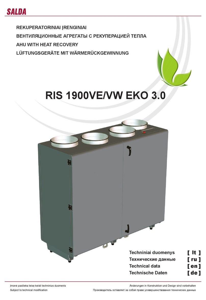
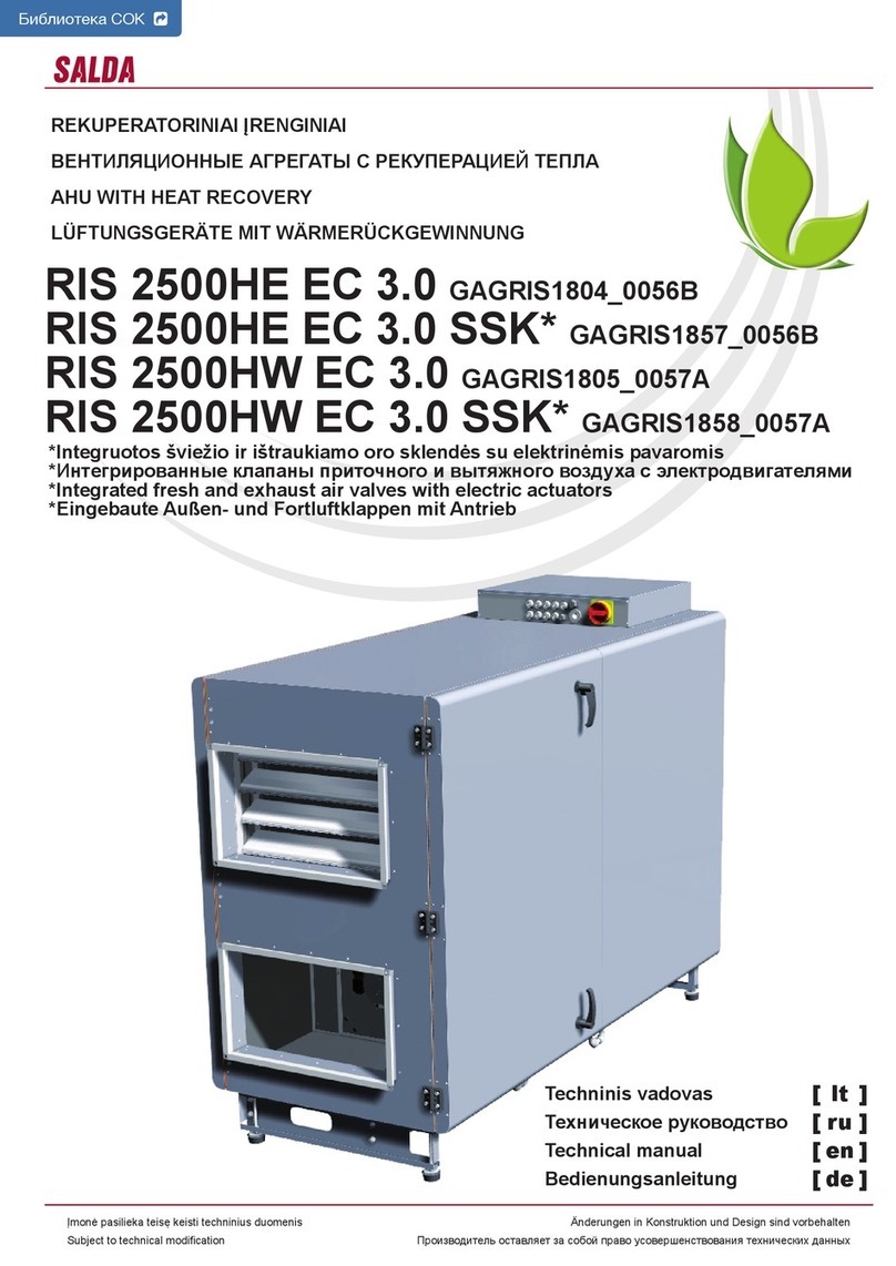
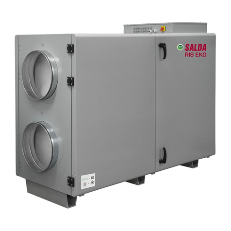
RIS 1200PE/PW EKO 3.0
RIS 1900PE/PW EKO 3.0
RIS 2500PE/PW EKO 3.0
2www.salda.lt
[ it ] [ ru ] [ en ] [ de ]
RIS 1200_1900_2500PE/PW EKO 3.0
[ IT ] Indice
Trasporto e stoccaggio 4
Descrizione 4
Misure di sicurezza 4
Componenti 5
Condizioni d’impiego 5
Manutenzione 6
Filtri 6
Ventilatore 6
Scambiatore di calore 7
Batteria elettrica 8
Garanzia 8
Dati tecnici 9
Filtri 10
Dimensioni 10
Montaggio 11
Scarico condensa v1 12
Scarico condensa v2 13
Schema dei componenti 14
Accessori 15
Collegamenti delle batterie ad acqua AVA/AVS 16
Unità di controllo 16
Protezione del sistema 18
Uso dell‘unità un una rete BMS 19
Indirizzi ModBus 20
Connessione elettrica dell‘unità HVAC 21
Guida per la riparazione del sistema 22
Guasti principali dell’unità HVAC e soluzioni per eliminarli 24
Scheda di controllo RG1 27
Signicato dei LED 28
Designazione convenzionale, caratteristiche del processore e dei gruppi
del sistema 28
Controllo periodico dell’unità 31
Schema elettrico 32
Tabella di manutenzione del prodotto 36
[ RU ] Содержание
Транспортировка и хранение 4
Описание 4
Меры предосторожности 4
Компоненты 5
Условия работы 5
Обслуживание 6
Фильтры 6
Вентилятор 6
Теплообменник 7
Электрический нагреватель (RIS PE EKO 3.0) 8
Гарантия 8
Технические данные 9
Фильтры 10
Размеры 10
Установка 11
Дренаж v1 12
Дренаж v2 13
Cхема комплектующих 14
Принадлежности 15
Варианты подключения AVA/AVS 16
Автоматика управления 16
Защита системы 18
Использование агрегата в сети BMS 19
Адреса ModBus 20
Электрическое подключение агрегата ОВК 21
Рекомендации по наладке системы 22
Основные неисправности агрегата ОВК и способы их устранения 24
Пульт управления RG1 27
LED индикации контроллера 28
Условные обозначения, параметры узлов и системы 28
Периодическая проверка системы 31
Схема електрическое подключение 32
Таблица обслуживание продукта 36
3
www.salda.lt
[ it ] [ ru ] [ en ] [ de ]
RIS 1200_1900_2500PE/PW EKO 3.0
[ EN ] Contents
Transportation and storage 4
Description 4
Safety precautions 4
Components 5
Operating conditions 5
Maintenance 6
Filters 6
Fan 6
Heat exchanger 7
Electrical heater (RIS PE EKO 3.0) 8
Warranty 8
Technical data 9
Filters 10
Dimensions 10
Mounting 11
Draining v1 12
Draining v2 13
Scheme for components 14
Accessories 15
AVA/AVS connecting options 16
Automatic control 16
System protection 18
Using the unit in BMS network 19
ModBus adresses 20
Electrical connection of the HVAC 21
System adjustment guidelines 22
Basic failures of the HVAC unit and troubleshooting 24
Control board RG1 27
LED indications of the controller 28
Labeling, characteristics of the controller and the system comp nents 28
Regular system check-up 31
Electrical connection diagram 32
Product maintenance table 36
[ DE ] Inhalt
Transport und Lagerung 4
Beschreibung 4
Schutzmassnahmen 4
Bestandeile des Gerätes 5
Betriebsbedingungen 5
Bedienung 6
Filter 6
Ventilator 6
Wärmetauscher 7
Elektroheizung (RIS PE EKO 3.0) 8
Garantie 8
Technische Daten 9
Filter 10
Abmessungen 10
Montage 11
Kondensatablauf v1 12
Kondensatablauf v2 13
Aufbauschema mit Bestandteile des Gerätes 14
Zubehöre 15
Montage-Varianten vom AVA/AVS 16
Automatische Steuerung 16
Systemschutz 18
Verwendung des Gerätes im BMS-Netz 19
ModBus-Adressen 20
Elektrischer Anschluss der Heizung-, Lüftung- und Klimaeinrichtung 21
Empfehlungen für die Abstimmung des Systems 22
Hauptstörungen der Heizung-, Lüftung- und Klimaeinrichtung sowie Meth-
oden ihrer Beseitigung 24
Steuerplatine RG1 27
LED-Indikationen des Kontrollers 28
Übereinstimmende Kennzeichnungen, Parameter des Kontrollers sowie
der System-Baueinheiten 28
Regelmäßige Systemkontrolle 31
Elektrische Erwärmungseinrichtung 32
Wartungstabelle des Produktes 36
4www.salda.lt
[ it ] [ ru ] [ en ] [ de ]
RIS 1200_1900_2500PE/PW EKO 3.0
L’imballo di tutte le unità garantisce l’integrità
del prodotto in condizioni normali di trasporto.
Dopo aver tolto l’unità dall’imballaggio, con-
trollare che non sia stata danneggiata durante
il trasporto. È assolutamente vietato montare
unità danneggiate!!!
L’imballaggio è solo un mezzo di protezione!
Caricando e scaricando le unità, usare mezzi
di sollevamento appropriati per evitare danni e
lesioni. Non sollevare mai le unità per mezzo
dei cavi di alimentazione, per le scatole di con-
nessione, ange di aspirazione o di espulsione.
Evitare urti o forti sollecitazioni al corpo dell’unità.
Conservare le unità in un locale asciutto in cui
l’umidità relativa non deve superare il 70% (a una
temperatura di +20°C), e la temperatura media
deve essere mantenuta tra i +5°C e +30°C.
Immagazzinare le unità in luoghi asciutti ed al
riparo dall’acqua e dallo sporco.
Le unità devono essere movimentate mediante
un carrello elevatore.
È sconsigliato lo stoccaggio per un periodo
superiore ad un anno. In caso di stoccaggio
per un periodo superiore ad un anno, prima del
montaggio controllare se i cuscinetti dei ventila-
tori e dei motori girano facilmente (far girare la
ventola con una mano), vericare l’integrità del
isolamento del circuito elettrico, controllare che
non vi siano segni di umidità.
- Не используйте агрегат по другим целям, не-
жели указано в его предназначении.
- Не разбирайте и никаким образом не модер-
низируйте агрегат. Это может стать причиной
механической поломки или ранения.
- Во время монтажа и обслуживания агрегата
используйте специальную рабочую одежду и
будьте осторожны - углы агрегата и составля-
ющих частей могут быть острыми и ранящими.
- Во время работы агрегата не прикосайтесь и
остерегайтесь, чтобы прочие предметы не по-
пали в решетки подачи и вытяжки воздуха или в
подключенный воздуховод. При попадании лю-
бого постороннего предмета в агрегат немед-
ленно отключите от источника питания. Перед
- Do not use the unit for purposes other than
its’ intended use.
- Do not disassemble or modify the unit in any
way. Doing so may lead to mechanical failure
or injury.
- Use special clothing and be careful while
performing maintenance and repair jobs - the
unit’s and its components edges may be sharp
and cutting.
- Do not wear loose clothing that could be
entangled in to operating unit.
- Do not place ngers or other foreign objects
through inlet or exhaust guards or into con-
nected duct. Should a foreign object enter the
unit, immediatelly disconnect power source.
- Die Anlage darf nur für den dafür vorgesehenen
Zweck gemäß Bedienungsanleitung verwendet
werden.
- Die Demontage und Montage darf nur gemäß
der Betriebsanleitung vorgenommen werden
(Verletzungsgefahr oder Gefahr mechanischer
Störungen)
- Bei der Montage und Inbetriebnahme muss
Sicherheitskleidung getragen werden. Vorsicht:
die Winkel und Kanten der Anlage und der Kom-
ponenten können scharf sein und Verletzungen
verursachen;
- Bei der Arbeit sollte eng anliegende Kleidung
getragen werden!
- Weder Finger noch Gegenstände in die Zu- oder
I recuperatori di calore sono unità di ventilazio-
ne per il ricambio e la ltrazione dell’aria. Me-
diante lo scambiatore di calore l’energia termica
contenuta nell’aria espulsa viene recuperata
e ceduta all’aria immessa. Sono costituiti da:
• Scambiatore di calore a piastre con rendi-
mento termico no al 90%.
• By-pass automatico con valvola motorizzata
integrata.
• Batteria elettrica integrata, tipo di comando:
0-10V (solo RIS PE EKO 3.0).
• Ventilatori EC ad alta e󰀩cienza e silenziosità.
• Basso assorbimento elettrico: SFP (Specic
Fan Power) calcolato secondo EN13779
• Interruttore di sicurezza integrato EN 60204-
1:2006. (solo RIS PE EKO 3.0).
• 30 mm di isolamento acustico e termico
dell’involucro.
• Controllo automatico integrato, connessione
„Plug and Play“.
•Filtri paini F7/M5.
• La fornitura include: TL - sensore temperatura
dell’aria esterna, TJ - sensore temperatura aria
immessa, TE - sensore temperatura aria espul-
sa, DTJ100 - sensore di umidità e temperatura
sull’aria estratta.
• In versione standard il recuperatore viene
fornito con la logica di tipo V2.
Non adatto all’uso all’interno di piscine,
nelle saune e in altri ambienti simili.
Recuperatore di calore non può essere uti-
lizzato come un riscaldatore dell’aria.
La fornitura standard include (senza accessori
opzionali):
1) dispositivo di ventilazione;
2) Sensore temperatura aria immessa (TJ) 1
pz. (con batteria elettrica);
3) Kit antigelo per SVS (con batteria ad acqua)
- Non usare questo dispositivo per scopi diversi
da quelli previsti.
- Non manomettere e non modicare il dispo-
sitivo. Ciò può provocare guasti meccanici o
funzionali.
- E󰀨ettuare il montaggio e i lavori di manuten-
zione indossando abbigliamento e protezioni
adeguate. Prestare attenzione: gli spigoli del
dispositivo e dei suoi componenti possono
essere taglienti e appuntiti.
- Non indossare abiti larghi e non aderenti
che possano essere risucchiati dal ventilatore
in azione.
- Non inserire le dita o altri oggetti nella griglia
di aspirazione e di scarico dell'aria e nella
Все оборудование упаковано так, чтобы вы-
держало нормальные условия перевозки.
После распаковки убедитесь в отсутствии
повреждений при транспортировке. Уста-
новка поврежденных устройств запрещена!
Упаковка является только средством за-
щиты!
С целью избегания убытков и травм при раз-
грузке и складировании устройств пользуй-
тесь соответствующим подъемным оборудо-
ванием. Не поднимайте устройства за кабе-
ли питания, коробки подключения, фланцы
забора или удаления воздуха. Избегайте со-
трясений и ударных перегрузок. Устройства
храните в сухом помещении, где относитель-
ная влажность воздуха не превышает 70 проц.
(при +20ºС), а средняя температура окружа-
ющей среды составляет от +5ºC до +30ºС.
Место складирования должно быть защище-
но от грязи и воды.
Устройства на место их складирования или
установки доставляются подъемниками.
Не советуется складировать устройства
дольше одного года. При более длительном
хранении перед установкой необходимо убе-
диться в легкости хода подшипников венти-
ляторов и двигателей (повернуть крыльчатку
рукой), в отсутствии повреждений изоляции
электроцепи и конденсации влаги.
All units are packed in the factory to withstand
regular conditions of transportation.
Upon unpacking, check the unit for any dam-
ages caused during transportation. It is forbidden
to install damaged units!!!
The package is only for protection purpose!
While unloading and storing the units, use
suitable lifting equipment to avoid damages and
injuries. Do not lift units by holding on power
supply cables, connection boxes, air intake or
discharge anges. Avoid hits and shock over-
loads. Before installation units must be stored
in a dry room with the relative air humidity not
exceeding 70% (at +20°C) and with the average
ambient temperature ranging between +5°C and
+30°C. The place of storage must be protected
against dirt and water.
The units must be transported to the storage or
installation site using forklifts.
The storage is not recommended for a period
longer than one year. In case of storage longer
than one year, before the installation it is neces-
sary to verify whether the bearings of fans and
motor rotate easily (turn the impeller by hand)
and if the electric circuit insulation is not dam-
aged or the moisture is accumulated.
Alle Geräte sind werksseitig so verpackt,
dass sie den normalen Transportbedingungen
standhalten können.
Nach Auspacken des Gerätes überprüfen Sie,
ob es beim Transport nicht beschädigt wurde.
Beschädigte Geräte dürfen nicht montiert
werden!!!
Die Verpackung ist nur eine Schutzmaßnahme!
Beim Ausladen und Lagern der Geräte verwen-
den Sie geeignete Hebezeuge, um Schäden
und Verletzungen zu vermeiden. Heben Sie die
Geräte nicht an Netzkabeln, Anschlusskästen,
Zu- und Abluftstutzen. Vermeiden Sie Stöße und
Schläge. Lagern Sie die Geräte in einem trocke-
nen Raum, wo die relative Luftfeuchte höchstens
70% (bei +20°C) beträgt und die durchschnittli-
che Umgebungstemperatur zwischen +5°C und
+30°C liegt. Der Lagerort muss vor Schmutz und
Wasser geschützt sein.
An den Lager- bzw. Montageort werden die
Geräte mit Hebezeugen transportiert.
Eine Lagerung länger als ein Jahr ist nicht
empfehlenswert. Bei einer Lagerung länger
als ein Jahr ist vor der Montage unbedingt zu
prüfen, ob die Ventilator- und Motorlager leicht-
gängig sind (Flügelrad mit der Hand drehen),
ob die Isolierung des elektrischen Stromkreises
nicht beschädigt ist und sich keine Feuchtigkeit
angesammelt hat.
Рекуператоры – это вентиляционные устрой-
ства, которые очищают, согревают и подают
свежий воздух. Устройства отбирают тепло
из вытяжного воздуха и передают его при-
точному.
Роторный теплообменник, тепловая эффек-
тивность которого – до 90 проц.
Интегрированная моторизованная обходная
заслонка (“By-pass”).
Интегрированный электрический нагрева-
тель, тип управления: релейной вход/выход
(только RIS PE EKO 3.0).
Производительные и тихо работающие ЕС
вентиляторы.
Низкий уровень SFP (Specic Fan Power)
EN13779.
Интегрированный переключатель безопас-
ного отключения EN 60204-1:2006. (только
RIS PE EKO 3.0).
Акустическая и тепловая 50 мм изоляция
наружных стенок.
Интегрированная автоматика управления,
подключение “Plug and Play”.
Панельные фильтры F7/M5.
В комплект входят датчики: TL - темп. све-
жего воздуха, TJ - темп. приточного воздуха,
TE - темп. выбрасываемого воздуха, DTJ100
- влажност и темп. вытяжного воздухa.
Стандартно поставляется с контроллером
автоматики V2.
Не приспособлен для использования в
бассейнах, банях и других подобных по-
мещениях. Рекуператор не может приме-
няться как нагреватель воздуха.
В стандартную упаковку (кроме дополни-
тельно заказываемых приложений) входят:
1) вентиляторное устройство;
2) Датчик температуры приточного воздуха
(TJ)1 шт (когда электрический нагреватель)
3) Комплект защиты от замерзания для SVS
(для водонагревателя)
AHUs are air ventilation devices that clean,
heat and supply fresh air. Units take heat from
exhausted air and transmit it to supply air.
Пластинчатый теплообменник, тепловая
эффективность которого – до 90 проц.
Integrated motorized by-pass valve.
Integrated electrical heater, Control type: relay
in/out (just RIS PE EKO 3.0).
E󰀩cient and silent EC fans.
Low SFP (Specic Fan Power) level EN13779.
Integrated safety cut-off switch EN 60204-
1:2006. (just RIS PE EKO 3.0).
Acoustic and thermal 50mm insulation of
external walls.
Integrated control automation, Plug and Play
connection.
Panel lters F7/M5.
Package includes: TL - temp. sensor for fresh
air, TJ - temp. sensor for supply air, TE - temp.
sensor for exhaust air, DTJ100 - temp. and
humidity sensor for extract air.
As standard, supplied with Ewith automatic
controller V2.
Not suitable for use at swimming pools,
saunas and other similar facilities. The unit
can not be used as an air heater.
Standard package (without optional acces-
sories) includes:
1) Ventilation unit;
2) Supply air temp. sensor (TJ)- 1pcs (for
electric heater)
3) Frost Protection Kit for SVS (for water heater)
WRG-Ventilatoren sind Lüftungsgeräte, die
reinigen, erwärmen und liefern frische Luft. Die
Geräte nehmen die Wärme von der Abluft und
übergibt sie der Luft, die geliefert wird.
Plattenwärmeaustauscher, dessen Tempera-
turleistung bis 90 % beträgt.
Integrierter motorisierter Bypass-Klappe.
Integrierter elektrischer Wärmer, Steu rungstyp:
Relais in / out (nur RIS PE EKO 3.0).
Leistungsfähige und leise EC-Ventilatoren.
Niedriges SFP-Niveau (Specic Fan Power)
laut EN 13779.
Integrierter Abtrennschalter laut EN 60204-
1:2006. (nur RIS PE EKO 3.0).
Lärm- und Wärmedämmung der 50 mm-
Außenwände.
Integrierte Steuerautomatik, Plug and Play-
Anschluss.
Plattenlter F7/M5.
Im Lieferumfang enthalten: TL- Außenluft-
temperaturfühler, TJ - Zulufttemperaturfühler,
TE - Ablufttemperaturfühler, DTJ100 - Abluft-
feuchte- und Temperaturfühler.
V2 Automatik-Regler gehört zum seriellen
Lieferumfang.
Nicht für Betrieb in Schwimmbädern, Sau-
nen und ähnlichen Räumen bestimmt. Das
Lüftungsgerät darf für Heizungszwecke
nicht verwendet werden.
Zur Standardverpackung (ohne Zubehör, das
zusätzlich bestellt wird) gehören:
1) Lüftungsgerät;
2) Zulufttemperaturfühler (TJ): 1 Stck. (wenn
mit elektrischer Wärmer);
3) SVS Frostschutz Kit (wenn mit Wasser-
register)
5
www.salda.lt
[ it ] [ ru ] [ en ] [ de ]
RIS 1200_1900_2500PE/PW EKO 3.0
изъятием постороннего предмета убедитесь,
что в вентиляторе остановилось любое механи-
ческое движение и удостоверьтесь, что случай-
ное включение агрегата невозможно.
- Не подключайте к электрической сети с ины-
ми данными, чем предъявленные на наклей-
ке с тех. данными модели на корпусе агрегата.
- Подберите и используйте внешний включа-
тель - автоматический предохранитель в со-
ответствии с электрическими параметрами
предъявленными на наклейке с тех. данными
модели на корпусе агрегата.
- Кабель питания должен быть подобран в со-
ответствии с мощностью агрегата.
- Не используйте кабель питания с повреж-
денной изоляцией.
- Не берите подключенный в электросеть ка-
бель мокрыми руками.
- Не допускайте погружения кабеля питания
и разъемов в воду.
- Не устанавливайте и не используйте агрегат
на нестабильных подставках, неровных, кривых
и пр. неустойчивых поверхностях.
- Устанавливайте агрегат надежно, тем обе-
спечивая безопасное использование.
- Не используйте агрегат в взрывоопасной и
агрессивные элементы содержащей среде.
- Не пользуйтесь прибором, если электропро-
вод или штепсельная вилка испорчены или
повреждены. При наличии повреждений пре-
кратите эксплуатацию прибора и немедленно
замените поврежденные части.
- Для чистки электрической части или вклю-
чателей не пользуйтесь водой или другой
жидкостью.
- Заметив на электрической части жидкость,
прекратите эксплуатацию прибора.
- Выполнение работ по электрической части
при подключенном напряжении воспреще-
но. Когда клеммы отключены, степень защи-
ты соответствует IP00. Так можно прикасать-
ся к компонентам под опасным напряжением.
Before removing foreign object, make sure that
any mechanical motion has stopped, the heater
has cooled down and the restart is not possible.
- Do not connect to any other power voltage
source than indicated on the model label.
- Use external motor protection-switcher only
corresponding to the nominal current specica-
tion on the model label.
- Power cable should correspond to unit power
specications (see model label).
- Do not use power cable with frayed, cut, or
brittle insulation.
- Never handle energized power cable with
wet hands.
- Never let power cables or plug connections
lay in water.
- Do not place or operate unit on unsteady
surfaces and mounting frames.
- Mount the unit rmly to ensure safe operating.
- Never use this unit in any explosive or aggres-
sive elements containing environment.
- Do not use the device if external connections
are broken or damaged. If there are any defects,
stop operating the device and replace the dam-
aged parts immediately.
- Do not use water or another liquid to clean
electrical parts or connections.
- If you notice water on electrical parts or con-
nections, stop operating the device.
- Do not make any electrical connections when
the power is on. When the terminals are discon-
nected, the degree of protection is IP00. This
allows touching components with dangerous
voltages.
Abluftanschlüsse stecken.
- Sollten Fremdkörper in die Anlage gelangen,
Ventilator ordnungsgemäß stillsetzen und vom
Netz trennen. Vor Beseitigung des Fremdkörpers
Stillstand des Laufrades abwarten und die Hei-
zung abkühlen lassen! Gegen Wiedereinschalten
sichern!
- Die Anlage muss gemäß Typenschild und
Angaben des Herstellers angeschlossen werden.
- Anschluss mit Überlastungsschutzschalter
gemäß Angaben auf dem Typenschild.
- Die Netzzuleitung muss der Kapazität der Anlage
entsprechen.
- Die Verwendung einer beschädigten Zuleitung
ist unzulässig.
- Elektrische Kabel, welche unter Strom stehen,
NIE mit nassen Händen anfassen!
- Verlängerungskabel und Steckverbindungen
NIE mit Wasser in Berührung bringen.
- Anlage nicht auf schiefe Konsolen, unebene
oder instabile Flächen montieren und betreiben.
- Die Anlage muss stabil montiert werden, um
einen sicheren Betrieb zu gewährleisten.
-Die Anlage darf nicht in explosionsgefährdeter
Umgebung oder für aggressive Sto󰀨e verwendet
werden.
- Verwenden Sie das Gerät nicht, falls die Au-
ßenanschlüsse defekt oder beschädigt sind. Bei
Beschädigungen bitte das Gerät außer Betrieb
setzen und unverzüglich die beschädigten Teile
austauschen.
- Verwenden Sie kein Wasser bzw. sonstige
Flüssigkeiten für die Reinigung von Elektroteilen
oder –Anschlüssen.
- Falls Sie Flüssigkeiten an den Elektroteilen
oder –Anschlüssen bemerken, setzen Sie das
Gerät außer Betrieb.
- Es ist grundsätzlich verboten Arbeiten des
Elektroanschlusses unter Spannung durchzufüh-
ren. Wenn die Anschlussklemmen abgeschaltet
sind, ist das Schutzniveau IP00. So kann man
Komponente berühren, die die gefährliche
Spannung haben.
Устройство предназначено для работы тол-
ко в помещении.
Запрещается использование устройств в по-
тенциально взрывоопасной среде.
Устройство предназначено для подачи и вы-
тяжки из помещения только чистого воздуха
(без химических соединений, способствую-
щих коррозии металлов; без веществ, агрес-
сивных по отношению к цинку, пластмассе,
резине; без частиц твердых, липких и волок-
нистых материалов).
Рабочая температура и влажность вытяж-
ного и приточного воздуха приведены в та-
блице (Табл. 1).
Unit is designed to operate indoors only.
It is forbidden to use the unit in potentially
explosive environment.
Unit is designed to supply/extract only clean air
(free of chemical compounds causing metal cor-
rosion, of substances aggressive to zinc, plastic
and rubber, and of particles of solid, adhesive
and bred materials).
The working extract and supply air tempera-
tures, and humidity are given in the table (Tab. 1).
Das Gerät ist nur für Innenaufstellung bestimmt.
Die Geräte dürfen nicht in einer explosionsge-
fährdeten Atmosphäre betrieben werden.
Das Gerät ist nur für die Zufuhr/den Abzug von
ausschließlich sauberer Luft (ohne chemische
Verbindungen, die Metallkorrosion hervorrufen;
ohne aggressive Substanzen, die Zink, Kunst-
sto󰀨 und Gummi angreifen; ohne Partikeln von
festen, klebenden sowie faserigen Materialien)
in den/aus dem Raum gefertigt und bestimmt.
Abluft- und Zulufttemperatur sowie -feuchti keit
sind in der Tabelle (Tab.1) angegeben.
condotta dell'aria connessa. Nel caso in cui un
oggetto estraneo dovesse entrare nel disposi-
tivo, scollegare immediatamente il dispositivo
dalla fonte di alimentazione. Prima di estrarre
l'oggetto estraneo assicurarsi che tutte le parti
meccaniche del dispositivo siano ferme e che
la batteria si sia ra󰀨reddata. Inoitre, assicurarsi
che il dispositivo non possa essere avviato
accidentalmente.
- Non connettere il dispositivo a rete elettrica
diversa da quella indicata sull'adesivo presente
sull’involucro del dispositivo.
- Usare solo un interruttore esterno come
dispositivo di sicurezza automatico adatto
(vedere potenza e corrente nominale indicate
sull'adesivo del vostro modello).
- Il cavo di alimentazione scelto deve corrispon-
dere alla potenza del dispositivo.
- Mai usare un cavo di alimentazione dan-
neggiato.
- Mai toccare i cavi di alimentazione collegati
alla rete elettrica con le mani bagnate.
- Mai immergere i cavi di alimentazione e le
relative spine in acqua.
- Non montare e non usare il dispositivo su
supporti storti, su supercie irregolari o instabili.
- Fissare saldamente il dispositivo per garantire
un uso sicuro.
- Mai usare questo dispositivo in ambienti sa-
turi di esplosivi oppure in presenza di sostanze
aggressive.
- Non usare il dispositivo se le connessioni
esterne sono guaste o danneggiate. Nel caso
si dovessero verificare degli inconvenienti,
interrompere l'uso del dispositivo e sostituire
immediatamente le parti difettose.
- Non usare acqua e altri liquidi per pulire le
parti o i connettori elettrici.
- Se avete notato acqua sulle parti o sui con-
nettori elettrici, interrompete l'uso del dispositivo.
- È proibito e󰀨ettuare i collegamenti elettrici
sotto tensione. Con i morsetti scollegati il grado
di protezione è IP00.
Il dispositivo è predisposto per l’uso in locali
chiusi.
È vietato usare il dispositivo in ambienti poten-
zialmente saturi di esplosivi.
Il dispositivo è destinato a immetere/estrarre
solo aria pulita (priva di composti organici cor-
rosivi per metalli,; di sostanze aggressive per lo
zinco, per i materiali plastici, per la gomma,; di
particelle di sostanze dure, ap
Fig. 1
Та б. 1
Ta b . 1
Ta b . 1
È consentito collegare dispositivi esterni di ven-
tilazione solo dopo aver garantito le necessarie
condizioni imposte dal produttore:
• Dispositivi che, prima dell‘installazione, era-
no conservati nel magazzino, devono essere
ulteriormente sigillati per impedire l‘accumulo
dell‘umidità all‘interno del dispositivo.
• Se una volta installato il dispositivo non viene
usato costantemente, è necessario impedire la
penetrazione dell‘aria calda/umida attraverso le
condotte d‘aria e la formazione della condensa
all‘interno del dispositivo di ventilazione.
• le unità ventilanti vengono utilizzate saltua-
riamente, al momento del riavvio è necessario
che vengano fatte funzionare per un’ora alla
massima velocità al ne di evacuare eventuali
depositi di condensa.
• Alimentando la macchina l’elettronica viene
messa in tensione e se sono presenti batterie
idroniche queste devono essere alimentate con
Когда температура наружного воздуха ниже
-23 °гр. рекомендуем использовать электри-
ческий нагреватель.
Температура рабочей среды обязательно
должна быть между +5 и +40 ºC
Эксплуатируемые вне помещений вентиля-
ционные установки включаются только тогда,
когда обеспечиваются установленные изгото-
вителем обязательные условия:
• Герметичность установок, которые перед
монтажом складируются на объекте, должна
быть обеспечена с помощью дополнитель-
ных средств во избежание накопления влаги
внутри установки.
• Если установка после монтажа не вводится
в постоянную эксплуатацию, обязательно не-
обходимо обеспечить, чтобы в вентиляцион-
ную установку через воздуховоды не попадал
It is recommended to use electrical pre-heater
if the supply air temperature is below -23 oC.
Required ambient temperatures must be from
+5 oC to +40 oC.
The air handling units installed outdoors shall be
started only when the following obligatory condi-
tions established by the manufacturer are met:
• Units that are stored at the site before instal-
lation shall be sealed using additional means in
order to prevent the accumulation of moisture
inside the unit.
• If the unit is installed and is not started for
ontinuous operation, it must be ensured that no
warm/humid air enters the unit through air ducts
and that no moisture condensates inside the unit.
• If the ventilation units stand idle for a long
time or are started infrequently, the system must
be blown down at the maximum capacity 1/24
Bei Außentemperaturen unter -23 °C ist es zu
emphehlen ein Vorheizrgeister zu benutzen.
Temperatur der Arbeitsumgebung muss im
Bereich von +5…+40 °C liegen.
Die im Freien betriebenen Lüftungseinrichtun-
gen werden nur dann eingeschaltet, wenn alle
obligatorischen, durch Hersteller angegebenen
Bedingungen gewährleistet sind. Die Bedin-
gungen sind:
• Die bevor Montage in Baustelle gelagerten
Einrichtungen sollen zusätzlich verdichtet
werden, um die Feuchtigkeitsansammlung in
Einrichtung zu vermeiden.
• Wird die Einrichtung montiert, doch instand
nicht gesetzt, so soll der Durchuss von warmer
bzw. feuchter Luft in Lüftungseinrichtungen
verhindert werden, um Kondensatansammlung
in Einrichtung zu vermeiden.
Immissione
Приточный воздух
Supply
Zuluft
- temperatura min./max.
- температура мин./макс.
- temperature min./max.
- Temperatur min./max. [°C] -3 / +40
con batteria elettrica di
preriscaldamento
без преднагревателям
Without preheater
Ohne Vorheizregister
- temperatura min./max.
- температура мин./макс.
- temperature min./max.
- Temperatur min./max. [°C] -40 / +40
senza batteria elettrica di
preriscaldamento
c преднагревателям
with preheater
Mit Vorheizregister
- umidità
- влажность
- max. humidity
- max. Feuchtigkeit
[%] 90
Estrazione
Вытяжной воздух
Extract
Abluft
- temperatura min./max.
- температура мин./макс.
- temperature min./max.
- Temperatur min./max.
[°C] +15 / +40
- umidità
- влажность
- max. humidity
- max. Feuchtigkeit
[%] 60
6www.salda.lt
[ it ] [ ru ] [ en ] [ de ]
RIS 1200_1900_2500PE/PW EKO 3.0
теплый/ влажный воздух, и чтобы не проис-
ходила конденсация влаги внутри установки.
• В случае если установка не эксплуатиру-
ется в течение длительного времени, или
если вентиляционные установки включают-
ся редко, систему обязательно необходимо
продувать на полной мощности 1/24 h – про-
сушивать.
• Инсталлировано и подключено напряже-
ние к автоматике вентиляционной установ-
ки, система водяных изделий наполнена гли-
колем/водой.
В случае несоблюдения этих вышепере-
численных требований изготовитель име-
ет право не применять гарантию в отноше-
нии появившейся влаги/ воды в испорчен-
ных компонентах.
До -40°C температуры наружного возду-
ха агрегат можно использовать с электриче-
ским преднагревателям. Электрический пред-
нагреватель температуру наружного воздуха
поднимает до -3°C. Без электрического пред-
нагревателя агрегат будет работать до -3,5°C
когда включен алгоритм зашиты от замерза-
ния теплообменника «Toutside» или до рас-
считанной температуры когда включен алго-
ритм зашиты от замерзания теплообменни-
ка «Klingb». Алгоритм «Klingb» по температу-
ре и влажности вытяжного воздуха и по тем-
пературе наружного воздуха рассчитыва-
ет возможную температуру замерзания те-
плообменника.
Агрегат прекращает подачу свежего возду-
ха из за риска замерзания теплообменника
или низкой температуры наружного воздуха,
в противоположном случае агрегат возобнов-
ляет подачу свежего воздуха.
Заводские настройки по умолчанию: каж-
дые 3 часа агрегат на максимальной скоро-
сти вентиляторов возобновляет подачу воз-
духа на 5 минут. В данный момент проверя-
ется условия по «Toutside» алгоритму. Если
в момент проверки температура приточно-
го воздуха упадает ниже 15°C, тогда агрегат
прекращает подачу воздуха через 3 минуты.
Когда агрегат переходит в нормальный ра-
бочий режим сообщение на пульте дистанци-
онного управление выключается.
h to dehumidify.
• Voltage to the automatics of the unit is installed
and connected; the system of water products is
lled with glycol/water.
In case of failure to comply with the require-
ments set out above, the manufacturer shall have
the right not to apply the warranty in respect of
the occurrence of moisture/water in damaged
components.
The unit can work at -40 ° C only with outdoor
air pre-heater, which must warmed outdoor air
up to -3 ° C temperature. Without outdoor air
pre-heater, the unit will work only to -3.5 ° C
when using the Toutside anti-frost algorithm or
the calculated freezing temperature if Klingb
anti-frost algorithm is used. The Klingb anti-
frost algorithm calculates the potential freezing
temperature of the heat exchanger according
room air temperature, room humidity and outdoor
air temperature.
The unit is temporarily stopped due to the risk
of freezing the heat exchanger or because of
the low supply air temperature, the unit starts up
itself when the freezing risk disappear. Factory
that every 3 hours the unit starts up for ~ 5 min.
at the highest speed and check didn’t disap-
peared heat exchanger frost risk. If the reasons
have disappeared, the unit will work normally
at the speed that was set before the frost risk.
If the reasons have not disappeared, the unit
after 5 min. is temporarily stopped until the next
inspection. If during the test the temperature of
the supply air falls below the set limit, the unit is
stopped after about 3 minutes.
The message on the screen disappears only
when the unit goes into normal mode.
• Werden die Lüftungseinrichtungen nur selten
betrieben oder Betriebspausen ausgesetzt, so ist
das System einmal in 24 Stunden mit maximaler
Leistung zu belüften und zu trocknen.
• Die Steuerungselektronik der Lüftungsein-
richtung ist montiert und stromgespeist. Das
Wassersystem ist mit Mischung von Glykol und
Wasser befüllt.
Der Hersteller übernimmt keine Gewähr-
leistung, die im Folge der Nichtbeachtung
oben genannten Anweisungen und daraus
resultierenden Einrichtungsbeschädigungen
durch Feuchtigkeits-bzw. Wassereinwirkung
entstehen.
Das Gerät kann bis auf -40 ° C nur mit dem
Vorheizregister betrieben werden, die Außen-
lufttemperatur muss bis auf -3 ° C vorerwärmt
werden. Ohne Vorheizregister kann das Gerät
nur bis bis auf -3,5 ° C Aussentemperatur arbei-
ten, wenn Frostschutzstrategie nach Algorithmus
Toutside oder Frostschutzstrategie Klingb nach
berechnetem Frostpunkt verwedet wird. Klingb
Froststrategie berechnet das mögliche Einfrieren
des Wärmetauschers gemäß der Ablufttempe-
ratur aus dem Raum, Raumabluftfeuchte und
Aussenlufttemperatur.
Das Gerät wegen Frostgefahr und zu niedri-
gen Zulufttemperaturen wird vorübergehend
gestoppt. Das Gerät schaltet sich ein, wenn
die Voraussetzungen für das Einfrieren des
Wärmetauschers weg sind. Werkseinstellung
nach schaltet sich das Gerät jede 3 Stunden
für ca. 5 Minuten in höchster Stufe ein um zu
prüfen, ob die Voraussetzungen für Einfrieren
des Wärmetauschers weg sind.
Wenn die Voraussetuzngen für das Einfrieren
des Wärmetauschers weg sind, dann arbeitet
das Gerät weiter wie vorher eingestellt. Wenn
die Voraussetzngen für das Einfrieren des
Wärmetauschers nicht weg sind, dann wird das
Gerät nach 5 Minuten bis zur nächsten Überprü-
fung gestoppt. Wenn während der Prüfung die
Zulufttemperatur unter eingestellter Temperatur
runterfällt, dann wird das Gerät nach 3 Minuten
gestoppt.
Anzeige auf dem Bedienteil nur dann ver-
schwindet, wenn das Gerät in Normalbetrieb
zurückkommt.
1. Involucro
2. Filtro immissione
3. Filtro estrazione
4. Sensore temperatura di immissione
5. Ventilatore di aspirazione
1. Housing
2. Supply air lter
3. Exhaust air lter
4. Supply air temperature sensor
5. Exhaust air fan
1. Gehäuse
2. Zuluft-Filter
3. Abluft-Filer
4. Temperaturfühler der Zuluft
5. Abluft-Ventilator
1. Корпус
2. Фильтр приточного воздуха
3. Фильтр вытяжного воздуха
4. Датчик температуры приточного воздуха
5. Вентилятор вытяжного воздуха
acqua ed eventualmente acqua glicolata.
In caso di mancato adeguamento alle prescri-
zioni di cui sopra il produttore ha il diritto di an-
nullare la garanzia, qualora un guasto dell’unità
risulti causato dalla presenza di condensa sulla
parte elettronica della stessa.
L’unità può lavorare con temperatura dell’aria
esterna di -40° C soltanto con una batteria
elettrica antigelo che porti la temperatura no a
3°C. In assenza di batteria antigelo sulla presa
di aria esterna, l’unità può operare soltanto
con temperatura no a -3,5° C quando è attivo
il sistema antigelo basato sulla temperatura
esterna oppure quello basato sull’algoritmo
Klingenburg per il calcolo della temperatura
di formazione del ghiaccio. Questo algoritmo
calcola la temperatura presunta di formazione
del ghiaccio nello scambiatore basandosi sulla
temperatura ed U.R. dell’aria estratta e sulla
temperatura dell’aria esterna.
L’unità viene fermata momentaneamente
quando si presenta il rischio di gelo a causa
della temperatura di immissione troppo bassa
e poi viene riavviata quando il rischio di gelo
viene meno. Per vericare se tale rischio esista
ancora o meno, ogni tre ore l’unità si avvia
alla massima velocità e opera per 5 minuti.
Qualora le condizioni siano tornate favorevoli,
il recuperatore ricomincerà a funzionare al
regime di rotazione dei ventilatori impostato
precedentemente dall’utente. Se, al contrario,
le condizioni non sono tornate favorevoli, l’unità
si fermerà nuovamente no al successivo ciclo
di prova. Se durante tale ciclo la temperatura
dell’aria immessa dovesse scendere sotto il
limite impostato dalla fabbrica, l’unità verrebbe
fermata dopo circa 3 minuti.
Un messaggio che avverte della procedura
antigelo in atto appare sul pannello di comando
remoto e scompare soltanto quando il funziona-
mento torna ad essere quello normale.
7
www.salda.lt
[ it ] [ ru ] [ en ] [ de ]
RIS 1200_1900_2500PE/PW EKO 3.0
- Maintenance and repair should only be per-
formed by experienced and trained sta󰀨.
- The fan should be inspected and cleaned if
needed at least 1/year.
- Be sure the fan is disconnected from power
source before performing any maintenance
or repair.
- Proceed to maintenance and repair after any
rotation in the fan stopped.
- Observe sta󰀨 safety regulations during main-
tenance and repair.
- The motor is of heavy duty ball bearing con-
struction. The motor is completely sealed and
requires no lubrication for the life of the motor.
- Detach fan from the unit.
- Impeller should be specially checked for buil-up
material or dirt which may cause an imbalance.
Excessive imbalance can lead to accelerated
- Montage und Elektroarbeiten nur durch aus-
gebildetes und eingewiesenes Fachpersonal
und nach den jeweils zutre󰀨enden Vorschriften
ausführen.
- Die Anlage muss min. einmal pro Jahr geprüft
und gereinigt werden.
- Vor der Wartung oder Reparatur sicherstellen,
dass die Anlage vom Stromnetz getrennt ist.
- Arbeiten dürfen nur bei abgeschaltetem und
mechanischem Stillstand des Laufrades sowie
nach Abkühlung der Heizung vorgenommen
werden! Gegen Wiedereinschalten sichern!
- Arbeitssicherheitsregelungen bei der tech-
nischen Bedienung beachten.
- In der Motorkonstruktion sind hochwertige
Lager eingebaut. Die Lager sind eingepresst
und erfordern keine Schmierung.
- Ventilator von der Anlage abschalten.
- Работы по обслуживанию должны прово-
диться только опытными и квалифицирован-
ными специалистами.
- Осмотр и работы по обслуживанию долж-
ны проводиться не реже 1 раза в 6 месяцев.
- Сооблюдайте правила техники безопасно-
сти проводя работы по обслуживанию или
ремонту.
- Перед началом работ по обслуживанию или
ремонту убедитесь, что вентилятор отклю-
чен от питания.
- Приступайте к работам по обслуживанию
или ремонту только убедившись, что в вен-
тиляторе остановилось любое механиче-
ское движение.
- Подшипники запрессованы не требуют об-
служивания на весь срок службы двигателя.
- Отсоедините вентилятор от агрегата.
Dirty lters increase air resistance in the lter,
i.e. less air volume is supplied into the premises.
- Filter preferably should be exchanged with
a new one every 3 months or when the lter
clogging sensor indicates. (sensor available
as accessory).
Verunreinigte Filter erhöhen die Druckverluste,
d.h. ein geringeres Luftvolumen gelangt in die
Räume.
- Die Filter werden ca. alle 3 Monate ersetzt
bzw. je nach Signal der Filterüberwachung (Fil-
terwächter werden als Option geliefert).
Užsiteršę ltrai, didina oro pasipriešinimą, dėl
to sumažėja į patalpas paduodamo oro kiekis.
- È consigliabile sostituire i ogni 3-4 mesi op-
pure basandosi sulle indicazioni del sensore di
saturazione dei (il sensore viene fornito come
accessorio opzionale)).
Грязные фильтры повышают сопротивление
воздуха в нем, по этой причине в помеще-
ние попадает меньшее количество воздуха.
- Фильтр рекомендуется поменять на новый
каждые 3-4 месяца или по показаниям датчи-
ка загрязнения фильтров (датчик поставляет-
ся отдельно как аксессуар).
Unplug unit from mains rst and wait for 2
minutes (till fans fully stop) before opening
the covers.
Bevor die Gerätetüren geöffnet werden
dürfen, Gerät elektrisch vom Versorgungs-
netz trennen und etwa 2 Min. warten, bis die
Ventilatoren völlig stehen bleiben.
Prima di aprire lo sportello del dispositivo
staccare l’alimentatore della corrente e aspet-
tare che la rotazione dei ventilatori si arresti
completamente (2 min. circa).
Перед тем, как открывать дверцу агре-
гата, отключите агрегат от электросети и
подождите, пока вентиляторы остановят-
ся полностью (около 2 мин.).
- Solo personale esperto e qualificato può
e󰀨ettuare lavori di manutenzione straordinaria.
- Il ventilatore deve essere ispezionato visiva-
mente e pulito almeno una volta all’anno.
- Prima di e󰀨ettuare i lavori di manutenzione e
di riparazione assicurarsi che il dispositivo sia
scollegato dalla rete elettrica.
- E󰀨ettuare i lavori di manutenzione solo quando
tutte le parti del ventilatore si sono fermate.
- Durante i lavori di manutenzione tecnica, at-
tenersi alle opportune disposizioni di sicurezza
sul lavoro.
- Nel corpo del motore sono inseriti i cuscinetti
ad altre e󰀩cienza. Sono sigillati e non richiedono
alcuna lubricazione per tutta la durata della
vita del motore.
- Scollegare il ventilatore dall’unità.
- È necessario ispezionare accuratamente la
6. Attuatore valvola by-pass
7. Scambiatore di calore
8. Sensore temperatura di estrazione
9. Ventilatore di mandata
10. Batteria elettrica (Solo RIS PE EKO 3.0)
Valvola by-pass
12. Scatola di comando
13. Sensore umidità e temperatura della
estrazione
14. Pressostato aria di mandata
15. Pressostato aria estratta
16. Trasduttore di pressione della protezione
antigelo dello scambiatore di calore
6. Привод обходной заслонки
7. Теплообменник
8. Датчик температуры вытяжного воздуха
9. Вентилятор приточного воздуха
10. Электрический нагреватель (только RIS
PE EKO 3.0)
11. Обходная заслонка
12. Блок управления
13. Влажност и темп. вытяжного воздухa
14. Реле давления приточного воздуха
15. Реле давления вытяжного воздуха
16. Реле давления для защиты от замерзания
теплообменника
6. By-pass valve actuator
7. Heat Exchanger
8. Exhaust air temperature sensor
9. Supply air fan
10. Electrical heater (just RIS PE EKO 3.0)
11. By-pass valve
12. Control Box
13. Temp. and humidity sensor for extract air
14. Supply air di󰀨erential pressure switch
15. Extract air di󰀨erential pressure switch
16. Heat exchanger antifrost pressure switch
6. Antrieb der Bypass-Klappe
7. Wärmetauscher
8. Temperaturfühler der Abluft
9. Zuluft-Ventilator
10. Elektrischer Wärmer (nur RIS PE EKO 3.0)
11. Bypass-Klappe
12. Steuerkasten
13. Abluftfeuchte- und Temperaturfühler
14. Druckrelais der Zuluft
15. Druckrelais der Abluft
16. Frostschutzfühler des Wärmeübertragers
8www.salda.lt
[ it ] [ ru ] [ en ] [ de ]
RIS 1200_1900_2500PE/PW EKO 3.0
- Be sure the fan is disconnected from power
source before performing any maintenance
or repair.
- Proceed to maintenance and repair after any
rotation in the fan stopped.
- Clean it once a year.
- Firstly take out heat exchanger cassette care-
fully. Submerge it into a bath and wash with warm
soapy water (do not use soda). Then rinse it with
hot water and let it to dry up.
- Wird einmal jährlich gereinigt.
- Einmal jährlich reinigen.
- Zuerst vorsichtig die Kassette des Wärme-
tauschers herausziehen. In eine Wanne mit
warmem Seifenwasser tauchen und reinigen
(kein Sodawasser verwenden). Danach mit hei-
ßem Wasser durchspülen und trocknen lassen.
- Перед началом работ по обслуживанию или
ремонту убедитесь, что вентилятор отклю-
чен от питания.
- Приступайте к работам по обслуживанию
или ремонту только убедившись, что в вен-
тиляторе остановилось любое механиче-
ское движение.
- Теплообменник подлежит к чистке ежегодно.
- Прежде всего осторожно извлеките кассе-
ту, погрузите ее в ванну с теплой водой и мы-
лом (не применять соды). Промойте несиль-
ной струей горячей воды (слишком сильный
напор воды может деформировать пластин-
ки). Обратно в агрегат ставте только полно-
стью сухой теплообменник.
- Prima di e󰀨ettuare i lavori di manutenzione e
di riparazione assicurarsi che il dispositivo sia
scollegato dalla rete elettrica.
- E󰀨ettuare i lavori di manutenzione solo quando
tutte le parti dei ventilatori si sono fermate.
- La pulizia dello scambiatore di calore viene
e󰀨ettuata una volta all’anno.
- Estrarre delicatamente la cassetta dallo
scambiatore, immergerla in un recipiente con
acqua saponata (non usare bicarbonato di
sodio). Lavare la cassetta sotto un debole getto
d’acqua calda (un getto d’acqua troppo forte può
deformare le piastre). Reinserire lo scambiatore
di calore nel dispositivo solo quando sarà com-
pletamente asciutto.
girante del ventilatore, controllando che non
si sia accumulata polvere o altre sostanze che
potrebbero sbilanciare la ventola. Lo sbilancia-
mento provoca vibrazioni e accelera l’usura dei
cuscinetti del motore.
- Pulire la ventola e la parte interna del corpo
con acqua e detergente delicato non corrosivo.
- Per pulire la ventola non utilizzare apparecchi
ad altapressione, prodotti abrasivi, strumenti
appuntiti e solventi aggressivi che possono
gra󰀩are o danneggiare la ventola.
- Durante la pulizia della ventola non immergere
motore nell’acqua.
- Assicurarsi che i pesi di bilanciamento della
ventola siano nella loro sede.
- Assicurarsi che la ventola non sfreghi contro
il corpo dell’unità.
- Reinserire il ventilatore nel dispositivo. Colle-
gare alla rete elettrica.
- Se dopo la manutenzione il ventilatore non si
accende oppure la protezione termica entra in
azione, contattare il produttore.
- Тщательно осмотрите крыльчатку вентиля-
тора. Покрытие пылью или пр. материала-
ми может нарушить балансировку крылчат-
ки. Это вызывает вибрацию и ускоряет из-
нос подшипников двигателя.
- Крыльчатку следует чистить не агрессив-
ными, коррозию крылчатки и корпуса не вы-
зывающими моющими средствами и водой.
- Для чистки крыльчатки запрещаетса исполь-
зовать струю высокого давления, абразивные
материалы, острые предметы и агрессивные
расстворители, способные поцарапать или
повредить крыльчатку вентилятора.
- Во время чистки не погружайте крыльчат-
ку в жидкость.
- Убедитесь, что балансировочные грузики
крылчатки на своих местах.
- Убедитесь, что крылчатка не прикосает-
са к корпусу.
- Установите вентилятор обратно в агрегат и
подключите к электросети.
- Если обратно установленный вентилятор не
включается или срабатывает термоконтакт-
ная защита - обращайтесь к производителю.
wear on motor bearings and vibration.
- Clean impeller and inside housing with mild
detergent, water and damp, soft cloth.
- Do not use high pressure cleaner, abrasives,
sharp instruments or caustic solvents that may
scratch or damage housing and impeller.
- Do not plunge impeller into any uid.
- Make sure, that impeller’s balance weights
are not moved.
- Make sure the impeller is not hindered.
- Mount the fan back into the unit. Connect the
fan to power supply source.
- If the fan does not start after maintenance or
repair, contact the manufacturer.
- Die Flügel vom Ventilator auf Ablagerungen
und Staub prüfen, starke Verschmutzung kann
zu Unwucht führen. Die Unwucht verursacht
eine Vibration und schnelleren Lagerverschleiß.
- Flügel und Gehäuse mit einem sanften Rei-
nigungsmittel abwaschen, keine aggressiven
Putzmittel verwenden die das Material angreifen
könnten. Flügel und Gehäuse danach mit viel
Wasser gründlich reinigen, keine Hochdruck-
anlage, Putzmittel, scharfes Werkzeug oder
aggressive Sto󰀨e verwenden, die zu Kratzer
und Beschädigungen führen könnten.
- Beim Reinigen der Flügel Motor vor Feuch-
tigkeit und Nässe schützen.
- Prüfen, dass die Wuchtgewichte am Flügel
nicht verschoben werden.
- Flügel darf nicht am Gehäuse streifen.
- Montieren des Ventilators wieder in
der Anlage. Anschließen der Anlage ans
Stromnetz.
- Sollte sich nach Wartung der Anlage der
Ventilator nicht mehr einschalten lassen oder
der Thermokontaktschutz auslösen, an den
Hersteller wenden.
9
www.salda.lt
[ it ] [ ru ] [ en ] [ de ]
RIS 1200_1900_2500PE/PW EKO 3.0
Электрический нагреватель не требует до-
полнительного обслуживания. Необходимо
только вовремя менять фильтры, как ука-
зано выше.
Нагреватели имеют 2 тепловые защиты: с
автоматическим возвратом, которая сраба-
тывает при +50ºC, и с ручным возвратом, ко-
торая срабатывает при +100ºС.
Если сработала защита с ручным возвратом,
устройство должно быть отключено от источ-
ника питания. Подождите, пока не остынут
элементы накаливания и не перестанут кру-
титься вентиляторы. Обнаруженную причи-
ну неисправностей надо её удалить. Нажми-
те кнопку «reset», чтобы начать установку.
Определить неисправность может только
квалифицированный работник.
При необходимости электрический нагре-
ватель можно вынуть. Надо отключить элек-
трическое соединение от нагревателя и вы-
тащить нагреватель.
Electrical heater does not need to be serviced
additionally. It is compulsory to change lters as
described above.
Heaters have 2 thermal protections: auto-
matically self-resetting, which activates at +50°C
and the manually restored, which activates at
+100°C.
After the activation of the manually restored
protection, the unit must be disconnected from
the power supaply. Wait until the heating ele-
ments cool down and the fans stop rotating. After
identifying and removing the reason of failure,
to start the unit, press the “reset” button. The
failure can be identied only by a qualied
professional.
If necessary, the electrical heater can be re-
moved. Disconnect the electrical connector from
the heater and remove the heater.
Das Elektro-Heizregister bedarf keiner zusätz-
lichen Wartung. Es sind nur die Filter rechtzeitig
zu wechseln, wie oben aufgeführt.
Heizregister verfügen über 2 Wärmeschutz-
vorrichtungen: die mit einer automatischen
Rückstellung, die bei +50 ºC anspricht; die mit
einer manuellen Rückstellung, die bei +100 ºC
anspricht.
Bei Ansprechen der Schutzvorrichtung mit
manueller Rückstellung ist das Gerät vom
Stromnetz zu trennen. Abwarten, bis die Heiz-
körper sich abgekühlt haben und die Ventilatoren
zum Stillstand gekommen sind. Nachdem das
Problem identiziert und gelöst ist, die „reset“
Taste drücken und das Gerät wieder in Betrieb
nehmen. Ausfall kann nur durch Fachperso-
nal festgestellt werden. Bei Bedarf kann das
Elektro-Heizregister herausgenommen werden.
Dazu den Stromanschluss am Heizregister
trennen und das Heizregister herausziehen.
La batteria elettrica non richiede alcuna manu-
tenzione particolare. È solo necessario sostituire
i ltri come descritto in precedenza.
La batteria elettrica è dotata di 2 protezioni
termiche: una protezione con reset automatico
che si attiva a +50 ºC e una con reset manuale
che si attiva a +100 ºC.
Nel caso di scatto to della protezione con
reset manuale bisogna scollegare il dispositivo
dalla fonte di alimentazione. Aspettare che si
ra󰀨reddino gli elementi riscaldanti e si fermi la
rotazione dei ventilatori. Individuare le cause
del guasto e risolverle. Premere il tasto “reset”e
riavviare il dispositivo.
Solo il personale qualicato può individuare
la causa del guasto.
Se necessario, la batteria elettrica può essere
rimossa. Per farlo, scollegare il connettore
elettrico della batteria e rimuoverla.
10 www.salda.lt
[ it ] [ ru ] [ en ] [ de ]
RIS 1200_1900_2500PE/PW EKO 3.0
RIS 1200PE 3.0
EKO 3.0
RIS 1200PE 6.0
EKO 3.0
RIS 1200PE 9.0
EKO 3.0
RIS 1200PW EKO
3.0
Batteria post riscaldamento
Нагреватель
Heizregister
Heater
- fase/tensione
- фаза/напряжение
- phase/voltage
- Phase/Spannung
[50 Hz/VAC] ~1, 230 ~3, 400 ~3, 400
SVS
500x250
- potenza assorbita
- потребляемая мощность
- power consumption
- Leistungsaufnahme
[kW] 3,0 6,0 9,0
Ventilatori
Вентиляторы
Fans
Ventilatoren
- fase/tensione
- фаза/напряжение
- phase/voltage
- Phase/Spannung
[50 Hz/VAC] ~1, 230
di estra-
zione
вытяжной
exhaust
abluft
- potenza/corrente
- мощность/сила тока
- power/current
- Nennleistung/Nennstrom
[kW/A] 0,37 / 2,5
- giri
- обороты
- speed
- Drehzahl
[min-1]3400
di immis-
sione
приточный
supply
zuluft
- potenza/corrente
- мощность/сила тока
- power/current
- Nennleistung/Nennstrom
[kW/A] 0,45 / 2,95
- giri
- обороты
- speed
- Drehzahl
[min-1]3400
- segnale di controllo
- сигнал управления
- control input
- Steuerungsignal
[VDC] 0-10
- classe di protezione
- класс защиты
- protection class
- Schutzart
IP-54
Potenza assorbita generale
Общая потребляемая мощность
Total power consumption
Total Leistungsaufnahme
- potenza/corrente
- мощность/сила тока
- power/current
- Nennleistung/Nennstrom
[kW/A] 3,82 / 18,49 6,82 / 14,19 9,82 / 18,49 0,82 / 5,49
Controllo automatico integrato
Авт. управление установлено
Automatic control integrated
Integriertes Steuerungsystem
+
Rendimento termico
Тепловая эффективность
Thermal e󰀩ciency
Thermischer Wirkungsgrad
80%
Isolamento dell’involucroe
Изоляция стенок
Insulation of walls
Isolation der Wände
[mm] 50
Peso
Вес
Weight
Gewicht
[kg] 170
Sezione del cavo di alimentazione
Сечение шнура питания
Cross-section of the power supply cable
Querschnitt Netzkabel
[mm²] 3x2,5 5x2,5 5x2,5 3x1,5
Dispositivo di protezione*
Защитное устройство*
Circuit breaker*
Sicherungsautomat*
Poliai
Полюса
Poles
Polzahl
1 3 3 1
I [A] B20 B20 B20 B10
Il produttore si riserva il diritto di apportare
modiche ai dati tecnici
Subject to technical modication Änderungen in Konstruktion und Design sind
vorbehalten
Производитель оставляет за собой право
усовершенствования технических данных
Thermal e󰀩ciency of RIS 1200PE/PW EKO 3.0 was calculated at 1200m³/h (indoor conditions +20o/60%; outdoor conditions -20o/90%)
* interruttore automatico con caratteristica B
* автоматический выключатель с характеристикой B
* automatic switch with characteristic B
*Automatikschalter mit B Charakteristik
11
www.salda.lt
[ it ] [ ru ] [ en ] [ de ]
RIS 1200_1900_2500PE/PW EKO 3.0
RIS 1900PE 3.0
EKO 3.0
RIS 1900PE 6.0
EKO 3.0
RIS 1900PE 12.0
EKO 3.0
RIS 1900PW EKO
3.0
Batteria post riscaldamento
Нагреватель
Heizregister
Heater
- fase/tensione
- фаза/напряжение
- phase/voltage
- Phase/Spannung
[50 Hz/VAC] ~1, 230 ~3, 400 ~3, 400
SVS
700x400
- potenza assorbita
- потребляемая мощность
- power consumption
- Leistungsaufnahme
[kW] 3,0 6,0 12,0
Ventilatori
Вентиляторы
Fans
Ventilatoren
- fase/tensione
- фаза/напряжение
- phase/voltage
- Phase/Spannung
[50 Hz/VAC] ~1, 230
di estra-
zione
вытяжной
exhaust
abluft
- potenza/corrente
- мощность/сила тока
- power/current
- Nennleistung/Nennstrom
[kW/A] 0,488 / 3,16
- giri
- обороты
- speed
- Drehzahl
[min-1]2540
di immis-
sione
приточный
supply
zuluft
- potenza/corrente
- мощность/сила тока
- power/current
- Nennleistung/Nennstrom
[kW/A] 0,485 / 3,12
- giri
- обороты
- speed
- Drehzahl
[min-1]2540
- segnale di controllo
- сигнал управления
- control input
- Steuerungsignal
[VDC] 0-10
- classe di protezione
- класс защиты
- protection class
- Schutzart
IP-54
Potenza assorbita generale
Общая потребляемая мощность
Total power consumption
Total Leistungsaufnahme
- potenza/corrente
- мощность/сила тока
- power/current
- Nennleistung/Nennstrom
[kW/A] 3,97 / 20,32 6,97 / 14,92 12,97 / 24,32 0,97 / 6,32
Controllo automatico integrato
Авт. управление установлено
Automatic control integrated
Integriertes Steuerungsystem
+
Rendimento termico
Тепловая эффективность
Thermal e󰀩ciency
Thermischer Wirkungsgrad
89,9%
Isolamento dell’involucroe
Изоляция стенок
Insulation of walls
Isolation der Wände
[mm] 50
Peso
Вес
Weight
Gewicht
[kg] 269,0 270,0 272,0 269,0
Sezione del cavo di alimentazione
Сечение шнура питания
Cross-section of the power supply cable
Querschnitt Netzkabel
[mm²] 3x4 5x2,5 5x4 3x1,5
Dispositivo di protezione*
Защитное устройство*
Circuit breaker*
Sicherungsautomat*
Poliai
Полюса
Poles
Polzahl
1 3 3 1
I [A] B25 B20 B30 B10
Il produttore si riserva il diritto di apportare
modiche ai dati tecnici
Subject to technical modication Änderungen in Konstruktion und Design sind
vorbehalten
Производитель оставляет за собой право
усовершенствования технических данных
Thermal e󰀩ciency of RIS 1900PE/PW EKO 3.0 was calculated at 1900m³/h (indoor conditions +20o/60%; outdoor conditions -20o/90%)
* interruttore automatico con caratteristica B
* автоматический выключатель с характеристикой B
* automatic switch with characteristic B
*Automatikschalter mit B Charakteristik
12 www.salda.lt
[ it ] [ ru ] [ en ] [ de ]
RIS 1200_1900_2500PE/PW EKO 3.0
Il produttore si riserva il diritto di apportare
modiche ai dati tecnici
Subject to technical modication Änderungen in Konstruktion und Design sind
vorbehalten
Производитель оставляет за собой право
усовершенствования технических данных
Thermal e󰀩ciency of RIS 2500PE/PW EKO 3.0 was calculated at 2500m³/h (indoor conditions +20o/60%; outdoor conditions -20o/90%)
* interruttore automatico con caratteristica B
* автоматический выключатель с характеристикой B
* automatic switch with characteristic B
*Automatikschalter mit B Charakteristik
RIS 2500PE 4.5
EKO 3.0
RIS 2500PE 9.0
EKO 3.0
RIS 2500PE 18.0
EKO 3.0
RIS 2500PW EKO
3.0
Batteria post riscaldamento
Нагреватель
Heizregister
Heater
- fase/tensione
- фаза/напряжение
- phase/voltage
- Phase/Spannung
[50 Hz/VAC] ~3, 400 ~3, 400 ~3, 400
SVS
700x400
- potenza assorbita
- потребляемая мощность
- power consumption
- Leistungsaufnahme
[kW] 4,5 9,0 18,0
Ventilatori
Вентиляторы
Fans
Ventilatoren
- fase/tensione
- фаза/напряжение
- phase/voltage
- Phase/Spannung
[50 Hz/VAC] ~1, 230
di estra-
zione
вытяжной
exhaust
abluft
- potenza/corrente
- мощность/сила тока
- power/current
- Nennleistung/Nennstrom
[kW/A] 0,675 / 3,0
- giri
- обороты
- speed
- Drehzahl
[min-1]2800
di immis-
sione
приточный
supply
zuluft
- potenza/corrente
- мощность/сила тока
- power/current
- Nennleistung/Nennstrom
[kW/A] 0,725 / 3,24
- giri
- обороты
- speed
- Drehzahl
[min-1]2800
- segnale di controllo
- сигнал управления
- control input
- Steuerungsignal
[VDC] 0-10
- classe di protezione
- класс защиты
- protection class
- Schutzart
IP-54
Potenza assorbita generale
Общая потребляемая мощность
Total power consumption
Total Leistungsaufnahme
- potenza/corrente
- мощность/сила тока
- power/current
- Nennleistung/Nennstrom
[kW/A] 5,87 / 12,5 10,7 / 19,5 19,7 / 33,1 1,4 / 6,7
Controllo automatico integrato
Авт. управление установлено
Automatic control integrated
Integriertes Steuerungsystem
+
Rendimento termico
Тепловая эффективность
Thermal e󰀩ciency
Thermischer Wirkungsgrad
90%
Isolamento dell’involucroe
Изоляция стенок
Insulation of walls
Isolation der Wände
[mm] 50
Peso
Вес
Weight
Gewicht
[kg] 316 320 322 313
Sezione del cavo di alimentazione
Сечение шнура питания
Cross-section of the power supply cable
Querschnitt Netzkabel
[mm²] 5x1,5 5x2,5 5x4,0 3x1,5
Dispositivo di protezione*
Защитное устройство*
Circuit breaker*
Sicherungsautomat*
Poliai
Полюса
Poles
Polzahl
3 3 3 1
I [A] B16 B25 B40 B10
13
www.salda.lt
[ it ] [ ru ] [ en ] [ de ]
RIS 1200_1900_2500PE/PW EKO 3.0
Il produttore si riserva il diritto di apportare
modiche ai dati tecnici
Subject to technical modication Änderungen in Konstruktion und Design sind
vorbehalten
Производитель оставляет за собой право
усовершенствования технических данных
RIS 1200PE/
PW EKO 3.0
RIS 1900PE/
PW EKO 3.0
RIS 2500PE/
PW EKO 3.0
Classe e dimensioni
dei ltri
Класс фильтров и
размеры
Filter class and
dimensions
Filterklasse und
Abmessungen
Di immissione
вытяжной
exhaust
abluft
F7 F7 F7
Larghezza
Ширина
Width
Breite
L [mm] 642 892 972
Altezza
Высота
Height
Höhe
H [mm] 258 340 440
Profondità
Глубина
Depth
Tiefe
L2 [mm] 90 46 46
Di estrazione
приточный
supply
zuluft
M5 M5 M5
Di estra-
zione
приточный
supply
zuluft
L [mm] 642 892 972
Altezza
Высота
Height
Höhe
H [mm] 258 340 440
Profondità
Глубина
Depth
Tiefe
L2 [mm] 90 46 46
Modello del ltro
Модель Фильтра
Filter model
Filter-Modell
MPL MPL MPL
500
686
391
355,5
250
51,5
1439
1653
1550
1319
172
1325
90
90
100
1497
1439
1397
RIS 1200PE/PW EKO 3.0
14 www.salda.lt
[ it ] [ ru ] [ en ] [ de ]
RIS 1200_1900_2500PE/PW EKO 3.0
524
708
592,4 592,4
403
1892
240
635
105
145
300
88
700145 700161
44
399
20
1750
592,4
468
60
592,4
524
60
402,5
RIS 1900PE/PW EKO 3.0
20 481
1850
625,7 625,7
60
557,5
60
506,5
715 415,5
290
625,7 557,5 625,7
1992
715
105
400
145
188
700145 700261
44
499
RIS 2500PE/PW EKO 3.0
15
www.salda.lt
[ it ] [ ru ] [ en ] [ de ]
RIS 1200_1900_2500PE/PW EKO 3.0
- Solo personale esperto e qualificato può
e󰀨ettuare il montaggio.
- Il dispositivo deve essere posizionato su una
supercie piana perfettamente orizzontale in
modo che il prodotto non sia inclinato (g. 01).
- Prima di collegare l’unità al sistema di condotte
dell’aria, le bocchette di collegamento delle
condotte dell’aria del dispositivo di ventilazione
devono essere aperte.
- Se necessario, il lato di servizio può essere
invertito.
- Durante il collegamento delle condotte
dell’aria, prestare attenzione alla direzione del
usso d’aria indicata sul corpo del dispositivo.
- Non collegare curve a gomito in prossimità
delle ange di collegamento. La distanza minima
da rispettare tra la prima curva o derivazione
deve essere 1xD per l’immissione, e di 3xD per
l’estrazione, dove D è il diametro della condotta
dell’aria.Per condotte rettangolari,
dove B la larghezza del condotto, H – altezza.
- Il montaggio deve essere e󰀨ettuato in modo
da evitare che il peso del sistema di condotte
dell’aria e dei suoi componenti sovraccarichi il
dispositivo di ventilazione.
- Durante il montaggio lasciare uno spazio
su󰀩ciente per aprire la porta di manutenzione
del dispositivo di ventilazione.
- È consigliabile e󰀨ettuare il montaggio a distan-
za di 400 mm dalla parete più vicina. Se non è
possibile, consigliamo di e󰀨ettuare il montaggio
su una parete connante con un locale in cui il
livello di rumore non importanza sia rilevante.
- Le vibrazioni prodotte dall’unità possono essere
trasmesse attraverso il pavimento. Se possibile,
isolare il pavimento in modo da ridurre il rumore
eventualmente prodotto dal dispositivo.
- Il collegamento dei tubi alla batteria elettrica
deve essere e󰀨ettuato in modo da permettere lo
smontaggio veloce dei tubi e la rimozione della
batteria dal corpo durante i lavori di manutenzio-
ne e di riparazione.
- I collegamenti dei tubi di immissione ed
estrazione devono essere e󰀨ettuati in modo
che la batteria funzioni in direzione opposta al
usso d’aria. Se la batteria funziona nella stessa
direzione dei ussi, diminuisce la di󰀨erenza
di temperatura media, il che inuisce sul suo
rendimento.
- In caso di possibile ingresso di condensa o
acqua dall‘esterno, è assolutamente necessario
installare una protezione esterna su presa aria
ed espulsione.
Fig. 01
Рис. 01
Pic. 01
Bild 01
- Монтажные работы должны выполнять-
ся только опытными и квалифицированными
специалистами.
-
Устройство должно быть смонтировано на ров-
ной горизонтальной поверхности так, чтобы оно
не имело наклона (рис. 01).
-
Перед тем как подключить вентиляционное
устройство к системе воздуховодов, отверстия
подключения воздуховодов устройства должны
быть аткрыты.
- Имеется возможность при необходимости из-
менить сторону обслуживания.
- При подсоединении воздуховодов обратите
внимание на направление воздушного потока,
указанное на корпусе устройства.
- Не подключайте колена вблизи фланцев под-
ключения устройства. Минимальный отрезок пря-
мого воздуховода между устройством и первым
разветвлением воздуховодов в канале забора воз-
духа должен составлять 1хD, а в канале выброса
воздуха 3хD, где D – диаметр воздуховода. Для
прямоугольных воздуховодов
где B – ширина воздуховода, H – высота
воздуховода.
- Монтаж необходимо произвести так, чтобы вес
системы воздуховодов и всех ее компонентов не
нагружал вентиляционное устройство.
- При установке необходимо оставить достаточ-
но места для открывания дверцы обслуживания
вентиляционного устройства.
- Если смонтированный приточный агрегат при-
слонен к стене, шумовые вибрации по ней мо-
гут передаваться в помещение, хотя уровень
шума работы вентиляторов является приемле-
мым. Советуется монтаж производить на рассто-
янии 400 мм от ближайшей стены. Если это не-
возможно, устройство рекомендуется монтиро-
вать рядом со стеной помещения, для которого
шум не так важен.
- Вибрация также может передаваться через
пол. Если имеется такая возможность, с целью
снижения уровня шума пол необходимо изоли-
ровать дополнительно.
- Трубопроводы к нагревателю подсоединяют-
ся так, чтобы при проведении работ по обслу-
живанию и ремонту можно было бы быстро раз-
монтировать и вынуть нагреватель из корпу-
са устройства.
- Трубопроводы с подающими и возвратными те-
плоносителями должны подключаться так, чтобы
нагреватель работал в направлении, противопо-
ложном направлению движения воздушного по-
тока. Если нагреватель работает в режиме пото-
ков того же направления, снижается средняя раз-
ница температур, влияющая на производитель-
ность нагревателя.
- Если существует возможность попадания кон-
денсата или воды на двигатель, необходимо уста-
новить наружные средства защиты.
- Installing should only be performed by qualied
and trained sta󰀨.
- The unit must be mounted on the at horizontal
surface so tas not to lean (Pic. 01).
- Before connecting to the air duct system, the
connection openings of ventilation system air
ducts must be opened.
- If necessary, the maintenance side can be
changed.
- When connecting air ducts, consider the air
ow directions indicated on the casing of the unit.
- Do not connect the bends near the connec-
tion anges of the unit. The minimum distance
of the straight air duct between the unit and the
rst branch of the air duct in the suction air duct
must be 1xD, in air exhaust duct 3xD, where D is
diameter of the air duct. For rectangular air ducts
where B – width of the air duct and H – height
of the air duct.
- Installation must be performed in such manner
that the weight of the air duct system and its com-
ponents would not overload the ventilation unit.
- Enough space must be left during installation
for opening of the maintenance door of the
ventilation unit.
- If the installed ventilation unit is adherent to
the wall, it may transmit noise vibrations to the
premises even though the level of noise caused
by the fans is admissible. The installation is rec-
ommended at the distance of 400 mm from the
nearest wall. If it is not possible, the installation
of the unit is recommended by the wall of the
room where the level of noise is not important.
- Also, vibrations can be transmitted through the
oor. If possible, additionally insulate the oor to
suppress the noise.
- Pipes are connected to the heater in such way
that they could be easily disassembled and the
heater could be removed from the unit casing
when performing service or repair works.
- Pipes with supply and return heat carriers must
be connected in such way that the heater would
work in the opposite direction for the air ow. If
the heater works using the same directions, the
mean temperature di󰀨erence decreases which
a󰀨ects the heater e󰀩ciency.
- If there is a possibility for condensate or water
to access the unit, external protective means
must be tted.
- Die Montage darf nur durch ausgebildetes
und eingewiesenes Fachpersonal durchgeführt
werden.
-
Das Gerät ist auf einer ebenen und horizontalen
Oberäche nicht geneigt zu montieren (Bild 01).
-
Vor dem Anschließen an das Luftleitungssys-
tem sind Luftleitungen Anschluss ö󰀨nen.
- Bei Bedarf besteht die Möglichkeit, die War-
tungsseite zu ändern.
- Beim Anschließen der Luftleitungen ist auf die
am Gerätegehäuse angegebenen Luftströmungs-
richtungen zu achten.
- Schließen Sie keine Bögen in der Nähe von
Geräteanschlussstutzen an. Der Mindestabstand
einer geraden Luftleitung zwischen dem Gerät
und der ersten Abzweigung in der Zuluftleitung
muss 1xD, in der Abluftleitung 3xD betragen (D
- Durchmesser der Luftleitung). Für rechteckige
Luftleitungen gilt:
B- Breite der Luftleitung, H- Höhe der Luft-
leitung.
- Beim Anschließen des Ventilators an das
Luftleitungssystem empfehlen wir, Zusatzkom-
ponenten
- Die Montage ist so durchzuführen, dass durch
das Gewicht des Luftleitungssystems und aller
seiner Bauteile keine Belastungen am Lüftungs-
gerät auftreten.
- Bei der Montage ist ein ausreichender
Schwenkbereich für die Wartungstür des Lüf-
tungsgerätes vorzusehen.
- Wird das Lüftungsgerät dicht an der Wand
montiert, können dadurch die Schallvibrationen
in den Raum übertragen werden, auch wenn der
Geräuschpegel der Ventilatoren akzeptabel ist.
Es ist zu empfehlen, die Montage in einem Ab-
stand von 400 mm zur nächstgelegenen Wand
durchzuführen. Ist dies nicht möglich, empfehlen
wir die Montage an einer Wand zu einem Raum,
für den der Lärm nicht wichtig ist.
- Die Schwingungen können auch über die
Fußböden übertragen werden. Besteht diese
Möglichkeit, sollten die Fußböden zusätzlich
isoliert werden, um den Lärm abzudämpfen.
- Die Rohrleitungen sind am Heizregister so
anzuschließen, dass sie bei Wartungs- und
Instandsetzungsarbeiten schnell demontiert
werden können, um das Heizregister aus dem
Gerätegehäuse herauszunehmen.
- Der Zu- und Rücklauf der Wärmeübertrager
ist so anzuschließen, dass das Heizregister
in entgegengesetzter Luftströmungsrichtung
funktioniert. Wird das Heizregister in gleicher
Strömungsrichtung betrieben, verringert sich
die mittlere Temperaturdi󰀨erenz, die die Leistung
des Heizregisters beeinusst.
- Besteht die Möglichkeit zum Eindringen von
Kondensat bzw. Wasser ins Gerät, sind externe
Schutzvorrichtungen anzubringen.
Sensori di temperatura dell'aria e sensori
proporzionali di qualità d'aria. I sensori di
temperatura dell'aria di immissione e i sensori
proporzionali di qualità dell'aria (se utilizzati
come opzione) devono essere montati il più
lontano possibile dall’unità ventilante (per quanto
permette la lunghezza del cavo del sensore) no
alla prima derivazione o curva della rete aerauli-
ca. È necessario attenersi a questa disposizione
per garantire la massima precisione del risuitato
di misurazione. Vedere la gura sottostante.
Датчики температуры воздуха
и преобразователя качества воздуха.
Датчики температуры приточного воздуха
и преобразователи качества воздуха
(если используются дополнительно) надо
смонтировать по возможности дальше от
вентиляционного оборудования (насколько
позволяет длина кабеля датчика) до
первого ответвления, поворота системы
транспортировки воздуха. Это необходимо
для того, чтобы результат измерения
был предельно точным. Смотреть ниже
расположенный рисунок.
Sensoren der Lufttemperatur und Umformer
der Luftqualität. Temperatursensoren der Zu-
luft sowie Umformer der Luftqualität (falls sie
zusätzlich verwendet werden) sollen möglichst
weit von den Lüftungsanlagen montiert werden
(je nach der Kabellänge des Sensors) bis zur
ersten Scheidung, Biegung des Systems der
Luftbeförderung. Diese Anforderung ist erforder-
lich, damit das Ergebnis der Messung möglichst
präzise ist. Siehe das Bild unten.
Air temperature sensors and air quality con-
verters. Supply air temperature sensors and air
quality transmitters (if additionally used) must be
mounted as far as possible from the ventilation
devices (within the connes of sensor cable) up
to the rst branch or turn of the air transportation
system. This requirement is necessary to ensure
the accuracy of measurement. See bellow gure.
16 www.salda.lt
[ it ] [ ru ] [ en ] [ de ]
RIS 1200_1900_2500PE/PW EKO 3.0
Рекуператор (1) строится на основание так,
чтобы сторона рекуператора (1) с трубкой
отвода конденсата (2) стояла 0 - 3 градусов
ниже чем другая сторона. Сторона рекупера-
тора (1) с трубкой отвода конденсата не может
быть ниже, чем другая сторона рекуператора!
Трубами (4) (металлическими, пластиковы-(4) (металлическими, пластиковы- (металлическими, пластиковы-
ми или резиновыми) соедините рекуператор
(1), сифон (3), и канализационную систему.
Трубы (4) должны иметь, не меньше чем (3)
градуса наклона вниз (1 метр трубы должен
быть наклонен вниз на 55 мм)!
Необходимо использовать сифон с об-
ратным клапаном (Принадлежност).
Система отвода конденсата эксплуатирует-
ся в помещениях, где температура не дости-
гает 0°С! Если температура ниже чем 0°С,
то система отвода конденсата должна быть
изолированна тепловой изоляцией или обо-
рудован подогрев.
Сифон (3) надо устанавливать ниже чем ре-
куператор (1).
AHU (1) is built on a foundation in a such way
that the side of AHU (1) with drainage exhaust
pipe (2) is lower 0° - 3° than the other side. The
side of AHU with drainage pipe can not be higher
than the other side.
The system must be connected with pipes (4)
in such order: AHU (1), siphon (3) and sewerage
system. Pipes (4) should be bended not less
than 3° (1 meter of pipe must be bended 55
mm downwards)!
It is necessary to use funnel trap for a drip-
ping condensate (Accessorie).
Draining system must be installed in the
premise where the temperature is not lower than
0°C. If temperature falls below 0°C the draining
system should be isolated with thermal isolation
or heating installed.
The siphon (3) must be mounted below the
AHU (1) level.
Das WRG-Gerät (1) wird so montiert, dass
die Seitenwand des WRG-Gerätes (1) mit dem
Auslassrohr des Kondensates (2) mit 0 - 3 Grad
niedriger als die andere Seitenwand steht. Die
Seitenwand des WRG-Gerätes (1) mit dem Aus-(1) mit dem Aus- mit dem Aus-
lassrohr des Kondensates darf nicht höher als
die andere Seitenwand stehen! Dann die Rohre
(Metall-, Plastik oder Gummirohre) (4) sowie in
angegebener Reihenfolge das WRG-Gerät (1),
Siphon (3) und das Abwassersystem zusam-
menschließen. Die Rohre (4) sollten mindestens
mit einem Winkel von (3) Grad verlaufen (1
Meter es Rohrs sollte 55mm Gefälle haben).
Es ist notwendig, Siphon für tropfende
Kondensat zu verwenden (Zubehör). Das
Ablaufsystem darf nur in Räumen betrieben
werden, in welchen die Raumtemperatur nicht
unter 0°C sinkt! Ansonsten muss das System mit
thermisch isoliert werden.
Der Siphon (3) muss unterhalb des WRG-
Gerätes (1) montiert werden.
Il recuperatore (1) deve essere posizionato su
una base in modo che il lato del recuperatore
(1) con il tubo di scarico della condensa (2) sia
di 0 – 3 gradi più basso dell’aitro lato. Il lato
del recuperatore (1) con il tubo di scarico della
condensa non deve assolutamente essere più
aito dell’aitro lato!
Usando i tubi (4) (in metallo, in plastica o in
gomma), collegare il recuperatore (1), il sifone
(3) e l’impianto di scarico tra loro nell’ordine
indicato. I tubi (4) devono essere inclinati di al-
meno 3 gradi (un tubo lungo 1 metro deve essere
inclinato di 55 mm verso il basso)!
È necessario usare il sifone con valvola di
ritegno (Accessorio non fornito).
Il sistema di scarico condensa è adatto all’uso
nei locali in cui la temperatura non deve essere
inferiore a 0°C! Se la temperatura può scendere
al di sotto di 0°C, bisogna provvedere ad un’ade-
guato isolamento termico del sistema oppure
installare impianto di riscaldamento.
Il sifone (3) deve essere più basso rispetto a
livello del recuperatore (1).
17
www.salda.lt
[ it ] [ ru ] [ en ] [ de ]
RIS 1200_1900_2500PE/PW EKO 3.0
L
NN N
LL
NC
NO
C
N
1A 4
1. Pompa dell’acqua
2. Interrutore automatico pompa
3. Recuperatore
4. Marrone
5. Blu
6. Verde
7. Nero
8. Giallo
9. Rosso
1. Водяной насос
2. Автоматический включатель для
насоса
3. Рекуператор
4. Kоричневый
5. Cиний
6. Зелёный
7. Черный
8. Желтый
9. Kрасный
1. Water pump
2. Automatic switch for water pump
3. AHU
4. Brown
5. Blue
6. Green
7. Black
8. Yellow
9. Red
1. Wasserpumpe
2. Automatische Schalter für Wasser-
pumpe
3. WRG-Ventilatoren
4. Brown
5. Blau
6. Grün
7. Schwarz
8. Gelb
9. Red
Vista dal lato di servizio
DTJ
DTJ
*
*
Espulsione
DTJ
DTJ
*
*
Estrazione
DTJ
DTJ
*
*
Presa d’aria
DTJ
DTJ
*
*
Immissione
Вид со стороны обслуживания
DTJ
DTJ
*
*
выбрасываемый воздух
DTJ
DTJ
*
*
вытяжной воздух
DTJ
DTJ
*
*
свежий воздух
DTJ
DTJ
*
*
приточный воздух
View from the inspection side
DTJ
DTJ
*
*
exhaust air
DTJ
DTJ
*
*
extract air
DTJ
DTJ
*
*
outdoor air
DTJ
DTJ
*
*
supply air
Von der Bedienseite aus betrachtet
DTJ
DTJ
*
*
Fortluft
DTJ
DTJ
*
*
Abluft
DTJ
DTJ
*
*
Aussenluft
DTJ
DTJ
*
*
Zuluft
DTJ
DTJ
*
*
DTJ
DTJ
*
*
DTJ
DTJ
*
*
DTJ
DTJ
*
*
DTJ
DTJ
*
*
DTJ
DTJ
*
*
DTJ
DTJ
*
*
DTJ
DTJ
*
*
RIS PE/PW R EKO 3.0 RIS PE/PW L EKO 3.0
In fase d‘ordine può essere scelta la versione
dell‘unità con presa aria esterna „destra“ oppure
„sinistra“.
В зависимости от заказанной версии уста-
новки, подачя наружнава воздуха возмож-
на с левой или с правой стораны установки.
Depends on version of the ordered, outdoor air
can be taken from the left or right side.
Lüftungsgeräte können je nach bestellter Ver-
sion mit Flanschanordnung für Aussenluft links
oder rechts eingebaut werden.
18 www.salda.lt
[ it ] [ ru ] [ en ] [ de ]
RIS 1200_1900_2500PE/PW EKO 3.0
IV - ventilatore estrazione
PV - ventilatore di immissione
KE - Batteria elettrica (solo RIS PE EKO 3.0)
PF - ltro immissione
IF - ltro estrazione
TJ - sensore temperatura immissione (fornito
insieme al sistema di controllo automatico
integrato)
TL - sensore della temperatura presa d’aria
esterna (fornito insieme al sistema di controllo
automatico integrato)
TA -sensore temperatura dell’aria aspirata
TE - sensore temperatura esplusione
DTJ - sensore umidità e temperatura estrazione
PS1 - pressostato aria di mandata
PS2 - pressostato aria estratta
PS3 - Trasduttore di pressione della protezione
antigelo dello scambiatore di caloreM4 - pompa
di circolazione della batteria ad acqua
M6 - valvola e motore
TV - sensore antigelo
T1 - sensore di temperatura
SVS - Batteria ad acqua per canale circolare
IV - exhaust air fan
PV - supply air fan
KE - electrical heater (just RIS PE EKO 3.0)
PF -  lter for supply air
IF -  lter for extract air
TJ - temperature sensor for supply air (supplied
in set with integrated automatic controll system)
TL - temperature sensor for fresh air (supplied
in set with integrated automatic controll system)
TE - temp. sensor for exhaust air
DTJ - temp. and humidity sensor for extract air
PS1 - Supply air di󰀨erential pressure switch
PS2 - Extract air di󰀨erential pressure switch
PS3 - Heat exchanger antifrost pressure switch
M4 - water heater circulator pump
M6 - Mixing valve and motor
TV - antifrost sensor
T1 - temperature sensor
SVS - heating coil for rectangular ducting
M1 - actuator of by-pass damper
PR - plate heat exchanger
M5 - Water cooler valve actuator (24VAC, 3-po-
sition control signal)
VV - Cooler 2-way valve
IV - вентилятор вытяжного воздуха
PV - вентилятор приточного воздуха
KE - электрический нагреватель (только
RIS PE EKO 3.0)
PF - фильтр для свежего воздуха
IF - фильтр для вытяжного воздуха
TJ - датчик темп. приточного воздуха
(поставляется в комплекте с ин- тегрированной
автомат. системой управления)
TL - датч и к темп. с в ежего возду х а
(поставляется в комплекте с ин- тегрированной
автомат. системой управления)
TE - темп. выбрасываемого воздуха
DTJ - влажност и темп. вытяжного воздухa
PS1 - Реле давления приточного воздуха
PS2 - Реле давления вытяжного воздуха
PS3 -Реле давления для защиты от
замерзания теплообменника
M4 - Циркуляционный насос водонагревателя
M6 - Kлапан и двигатель
TV - Датчик теплообменника
T1 - Датчик темп.
SVS - з м е е в и к д л я прямоугольн ы х
воздуховодов
M1 - двигатель воздухообводного клапана
by-pass
PR - пластинчатый теплообменник
M5 - Водяной охладитель клапана (24VAC,
3-позиционный управляющий сигнал)
VV - 2 ходовой клапан кулера
IV - Abluftventilator
PV - Zuluftventilator
KE - Elektro - Heizregister (nur RIS PE EKO 3.0)
PF - Außenluftlter
IF - Abluft lter
TJ - Zulufttemperaturfühler (Zusammen mit
Schaltschrank lieferbar)
TL - Aussenlufttemperaturfühler (Zusammen mit
Schaltschrank lieferbar)
TE - Ablufttemperaturfühler
DTJ - Abluftfeuchte- und Temperaturfühler
PS1 - Druckrelais der Zuluft
PS2 - Druckrelais der Abluft
PS3 - Frostschutzfühler des Wärmeübertragers
M4 - Durchlauferhitzer Umwälzpumpe
M6 - Mischer und Motor
TV - Frostschutzsensor
T1 - Temperaturfühler
SVS - Warmwasserheizregister für rechteckige
Kanäle
M1 - by-pass Klappe
PR - Kreuzstromwärmetauscher
M5 - Wasserkühler Ventilantrieb (24VAC, 3-Stel-
lung Steuersignal)
VV - 2-Wege-Ventil Wasserkühler
AVA
AVS
AVA
AVA
AVS
AVA
RIS PE EKO 3.0
RIS PW EKO 3.0
19
www.salda.lt
[ it ] [ ru ] [ en ] [ de ]
RIS 1200_1900_2500PE/PW EKO 3.0
Flex
Pannello di controllo remoto
Пульт управления
Remote controller
Fernbedienung
MPL
Filtri a pannello
Панельные фильтры
Panel lters
Paneel-Filter
RMG
Gruppo di miscelazione
Блок смешивание
Mixing point
Regelungseinheit
SSB
(RIS PW EKO 3.0)
Attuatore elettrico
Электромоторный привод
Electromotoric actuator
Elektromotorischer Stellantrieb
SP
Attuatore della serranda
Двигатель заслонки
Actuator for dampers
Klappenmotor
SPs
Attuatore della serranda con ritorno
a molla
Двигатель заслонки
Spring return actuator for damper
Stellantrieb mit Federrücklauf
VVP/VXP
(RIS PW EKO 3.0)
Valvola a 2-3 vie
2-3-ходовой клапан
2-3-way valve
2-3-Wege-Ventil
AKS3
Silenziatore per canale circolare
Сифон для сбора конденсата
Funnel trap for a dripping con-
densate
Sifon für Kondensat
WP
Pompa di scarico condensa
Водяной насос
Water pump
Wasserpumpe
SVS
(RIS PW EKO 3.0)
Batteria ad acqua
Водяной нагреватель
Water heater coil
Warmwasser Heizregister
SSP
LJ/E
Giunto antivibrante
Гибкое разъем
Flexible connection
Flexible Anschluss
LJ/PG
Giunto antivibrante
Гибкое разъем
Flexible connection
Flexible Anschluss
Silenziatore rettangolare
Глушитель для прямоугольных
каналов
Rectangular duct silencer
Schalldämpfer für rechteckige
Luftführungskanäle
RDC
Riduzione/Trasformazione
Переходник
Reducer
Übergang
Stouch
Pannello di controllo remoto
Пульт управления
Remote controller
Fernbedienung
CO2
Sensore di CO2
CO2преобразователь
CO2 transmitter
CO2 sender
S-1141
Sensore di pressione di󰀨erenziale
Дифференциальный датчик
давления
Di󰀨erential pressure transmitter
Di󰀨erenzdruck-Messumformer
1141
KCO2
RC02-F2
20 www.salda.lt
[ it ] [ ru ] [ en ] [ de ]
RIS 1200_1900_2500PE/PW EKO 3.0
TJ - Temperature sensor for supply air
T1 -Water heater antifreeze thermostat
TV - Water heater antifrost sensor
VV -Cooler 2-way valve
M4 - Circulation pump of the heater
M5 - Water cooler valve actuator (24VAC,
3-position control signal)
M6 - The heater valve actuator
TJ - Sensore temperatura immissione
T1 - Termostato antigelo della batteria ad acqua
TV - Sensore antigelo della batteria ad acqua
VV - Valvola per acqua a due vie della batteria
M4 - Pompa di circolazione della batteria
M5 - Attuatore della valvola della batteria ad
acqua (24VAC, segnale di controllo a 3 punti)
M6 - Attuatore della valvola della batteria
Температура приточного воздуха может ре-
гулироваться по температуре приточного
или вытяжного воздуха, измеренной датчи-
ком температуры воздуха и установленной
на пульте дистанционного управления по-
требителем. Температура приточного возду-
ха, установленная потребителем, поддержи-
вается пластинчатым (или роторным) тепло-
обменником и дополнительным электриче-
ским и/или водяным нагревателем (заказы-
вается в качестве приложения). Когда тем-
TJ - Zulufttemperaturfühler
T1 - Frostschutzthermostat Wasserregister
TV - Frostschutzfühler Wasserregister
VV - 2-Wege-Ventil Wasserkühler
M4 - Umwälzpumpe Wasserregister
M5 - Wasserkühler Ventilantrieb (24VAC,
3-Stellung Steuersignal)
M6 - Stellantrieb des Wasserventils
Supply air temperature can be adjusted ac-
cording to the temperature measured by the
supply or extracted air temperature sensor and
the temperature which is set by the user on the
remote control panel. User selected supply air
temperature is maintained by the plate (or ro-
tor) heat exchanger and additional electric and/
or water heater (optional). When the supply air
temperature is under the set temperature, by-
pass valve is closed (fresh ambient air passes
through the plate heat exchanger). If the device
Zulufttemperatur wird laut der Temperatur, die
durch den Fühler für Zu- und Ablufttemperatur
gemessen und durch den Benutzer im Fernbe-
dienungspult eingestellt ist, geregelt werden.
Die durch den Benutzer eingestellte Zulufttem-
peratur wird durch den Platten- (od. Rotor-)
Wärmetauscher und/oder einen zusätzlichen
Elektro- od. Wasserheizer (wird als Zusatz
bestellt) beibehalten. Wenn die Zulufttempera-
tur die eingestellte Temperatur unterschreitet,
wird die Bypass-Klappe geschlossen (frische
025 50 75 100
1200
%
Pa
300
600
900
60
720 0 - 1200Pa
0 - 100%
0 - 720Pa
0 - 60%
TJ - Датчик темп. приточного воздуха
T1 - Противозамерзающий термостат
водяного нагревателя
TV - Датчик противозамерзания водяно-
го нагревателя
VV - 2 ходовой клапан кулера
M4 - Циркуляционный насос нагревателя
M5 - Водяной охладитель клапана (24VAC,
3-позиционный управляющий сигнал)
M6 - Привод вентиля нагревателя
Esempio
Пример
Example
Exempel
La temperatura dell’aria di mandata può essere
regolata in base alla temperatura misurata dal
sensore dell’aria immessa e alla temperatura im-
postata dall’utente sul pannello di controllo remo-
to. La temperatura dell’aria immessa impostata
dall’utente viene mantenuta dallo scambiatore
di calore a piastre e in aggiunta dalla batteria
elettrica e/o quella ad acqua (fornita come
accessorio opzionale). Quando la temperatura
dell’aria immessa scende al di sotto del livello
impostato, la valova by-pass si chiude (l’aria fre-
NOTA: Se si usa la batteria elettrica, la connessione ra󰀩gurata non è possibile. Vedere paragrafo
„Batteria di mandata elettrica/ad acqua” nella sezione „Guida per la riparazione del sistema“.
ВНИМАНИЕ: Используя электрический нагреватель, данное подключение не допускается.
Смотрите раздел “Рекомендации по наладке системы” пункт “Электрический / водяной обо-
греватель приточного воздуха”.
NOTE: When using water heater, the above shown connecting is not possible. See paragraph
“Electrical/water supply air heater” in chapter “System adjustment guidelines”.
ANMERKUNG: Bei Verwendung vom Elektro-Register, angegebener Anschlus ist nicht möglich (s.
Kapitel “Empfehlungen für die Abstimmung des Systems”, Punkt “Elektrische Erwärmungseinrichtung
/Wasser-Erwärmungseinrichtung der Zuluft”).
NOTA: In condizioni normali, la valvola della batteria ad acqua può iniziare ad aprirsi in 30-90
minuti, a seconda della di󰀨erenza tra la temperatura impostata del setpoint e la temperatura misurata
dell’aria immessa (se l’unità si controlla in base alla temperatura dell’aria estratta, allora a seconda
della di󰀨erenza tra la temperatura impostata del setpoint e la temperatura misurata dell’aria estratta).
ВНИМАНИЕ: При нормальных условиях привод водяного нагревателя начнинает откры-
ваться через 30-90 минут, зависимо от разницы между температурами установленной пуль-
том управления и приточного воздуха (если управляется по температуре вытяжного возду-
ха, тогда разницу между заданным значением и показания температуры приточного воздуха).
NOTE: Under normal conditions, water cooler valve actuator can start opening in 30 -90 minutes due
to the temperatures’ di󰀨erence between the remote control panel set point and supply air temperature
(if the AHU is controlled according to exhaust air temperature, than the exhaust air temperature).
ANMERKUNG: Normalerweise ö󰀨net sich Antrieb des Wasserkühlers in 30-90 Minuten, ent-
sprechend nach Temperaturdiferenz zwischen auf dem Bedienteil eingestellter Temperatur und
Zulufttemperatur (wenn das Gerät nach Ablufttemperatur arbeitet, dann nach Ablufttemperatur).

Other manuals for RIS 1200PE/PW EKO 3.0

1

This manual suits for next models

2

Other Salda Fan manuals

Salda RIRS 5500 HER Operator's manual

Salda

Salda RIRS 5500 HER Operator's manual

Salda AKU 500x250 EKO User manual

Salda

Salda AKU 500x250 EKO User manual

Salda AMBERAIR User manual

Salda

Salda AMBERAIR User manual

Salda VKA 125 EKO User manual

Salda

Salda VKA 125 EKO User manual

Salda RIRS EKO 3.0 1200 HEL Guide

Salda

Salda RIRS EKO 3.0 1200 HEL Guide

Salda RIS 150P EKO User manual

Salda

Salda RIS 150P EKO User manual

Salda RIS 400HW Instruction manual

Salda

Salda RIS 400HW Instruction manual

Salda RIRS 1200HE EKO 3.0 User manual

Salda

Salda RIRS 1200HE EKO 3.0 User manual

Salda AMBERAIR COMPACT RH Series Guide

Salda

Salda AMBERAIR COMPACT RH Series Guide

Salda VSA EKO Series User manual

Salda

Salda VSA EKO Series User manual

Salda RIRS 5500HE EKO 3.0 User manual

Salda

Salda RIRS 5500HE EKO 3.0 User manual

Salda RIS 2500HE EKO 3.0 User manual

Salda

Salda RIS 2500HE EKO 3.0 User manual

Salda KF T120 Series Guide

Salda

Salda KF T120 Series Guide

Salda RIRS EKO 3.0 1900 HE Guide

Salda

Salda RIRS EKO 3.0 1900 HE Guide

Salda VSA 220 M 3.0 User manual

Salda

Salda VSA 220 M 3.0 User manual

Salda VSA 220 M 3.0 User manual

Salda

Salda VSA 220 M 3.0 User manual

Salda AMBERAIR User manual

Salda

Salda AMBERAIR User manual

Salda VSA 220 M 3.0 User manual

Salda

Salda VSA 220 M 3.0 User manual

Salda RIS 1900VE EC 3.0 Instruction manual

Salda

Salda RIS 1900VE EC 3.0 Instruction manual

Salda AKU Series Guide

Salda

Salda AKU Series Guide

Salda RIRS EKO 3.0 Series Guide

Salda

Salda RIRS EKO 3.0 Series Guide

Salda AMBERAIR COMPACT CX H Guide

Salda

Salda AMBERAIR COMPACT CX H Guide

Salda RIRS 5500VE EKO 3.0 User manual

Salda

Salda RIRS 5500VE EKO 3.0 User manual

Salda RIS 1900HE EC 3.0 User manual

Salda

Salda RIS 1900HE EC 3.0 User manual

Popular Fan manuals by other brands

Hunter 20174 Manual de Installatión y Operatión

Hunter

Hunter 20174 Manual de Installatión y Operatión

Hunter 23277 Manual de instalación

Hunter

Hunter 23277 Manual de instalación

Parrot Uncle F6209 Installation & operating instructions

Parrot Uncle

Parrot Uncle F6209 Installation & operating instructions

WilTec 34223 user manual

WilTec

WilTec 34223 user manual

Titon Vent Trex user guide

Titon

Titon Vent Trex user guide

Monte Carlo Fan Company 3CLMR56XXD Series Owner's guide and installation manual

Monte Carlo Fan Company

Monte Carlo Fan Company 3CLMR56XXD Series Owner's guide and installation manual

Element4 POWERFAN MKII Installation & user manual

Element4

Element4 POWERFAN MKII Installation & user manual

Nederman N Series user manual

Nederman

Nederman N Series user manual

Panasonic AC Fan Motor (ASEN9) Specifications

Panasonic

Panasonic AC Fan Motor (ASEN9) Specifications

Craftmade Phaze PHA52 installation guide

Craftmade

Craftmade Phaze PHA52 installation guide

Hunter 28496 Manual de Instalaсion y Operaсion

Hunter

Hunter 28496 Manual de Instalaсion y Operaсion

Taurus ALPATEC SIROCCO 18 manual

Taurus

Taurus ALPATEC SIROCCO 18 manual

ARDES AR5M41 Instructions for use

ARDES

ARDES AR5M41 Instructions for use

Exhale Fans EF34 Owner Guide & Installation Manual

Exhale Fans

Exhale Fans EF34 Owner Guide & Installation Manual

Sabiana Ocean ECM Instructions for installation, use and maintenance

Sabiana

Sabiana Ocean ECM Instructions for installation, use and maintenance

Mitsubishi Electric EF-35UDT-GL quick start guide

Mitsubishi Electric

Mitsubishi Electric EF-35UDT-GL quick start guide

Martec METRO DC Series installation guide

Martec

Martec METRO DC Series installation guide

Wolf FWL-PushPull-30 installation instructions

Wolf

Wolf FWL-PushPull-30 installation instructions

manuals.online logo
manuals.online logoBrands
  • About & Mission
  • Contact us
  • Privacy Policy
  • Terms and Conditions

Copyright 2025 Manuals.Online. All Rights Reserved.