manuals.online logo
Brands
  1. Home
  2. •
  3. Brands
  4. •
  5. Salus
  6. •
  7. Gateway
  8. •
  9. Salus SG888ZB Operation manual

Salus SG888ZB Operation manual

Universal Gateway (SG888ZB)
Installation/User Guide
IN THE BOX
SAFETY INSTRUCTIONS
Read these instructions before installing and using the
Gateway and keep this guide in a safe place for future
reference.
• Verify compatibility with your connected home system
before installation.
• Follow all instructions provided by your connected home
manufacturer regarding the addition of devices to your
connected home system. An authorized, qualified installer
may be required.
Salus accepts no responsibility for damage caused by not
following these instructions.
Gateway
Module
Ethernet Cable
USB
Adapter
USB Power
Cable
Installation / User
Guide
NOTE:Additional equipment may be required due to building construction or
materials, or other radio interference that may reduce the radio range.
INTRODUCTION
The Gateway, functioning as a Zigbee Co-Ordinator, is the primary
component of a Zigbee system. The Gateway creates the Zigbee
network, serves as the central hub for Zigbee communications, and
creates a bridge to the internet and SALUS Smart Home Cloud. The
Gateway hosts a flexible ‘Rules engine’ that allows users to create
‘Automations’ that allow data and/or functions from one device, to be
used as part of custom control sequences on other devices, using
simple, If/Then and And/Or logic.
CONTROLS,CONNECTIONS,AND INDICATORS
The Multi button on top of the Gateway is used to initiate various
modes. These are, to identify devices on the network, to Pair
compatible devices to the network, and to reset the Gateway to factory
default settings.
The LED Ring will turn different colors to indicate the Gateway status.
The Ethernet Port and Micro USB power port are located under the
port cover.
CONNECTING THE GATEWAY
To access the network and power ports, remove the port cover.
Connect the network cable first. Plug one end of the Ethernet cable
into the Gateway, the other end into an internet router (provided by
others).
Next plug the micro USB end of the USB cable into the Gateway port
and plug the other end into the USB power adapter, or USB power
adapter rated 5V @ 1A
GATEWAY INITIALIZATION
After power is applied, the Gateway will go through an initialization
process. The LED ring provides an indication of the connection status.
Green – during initial
power up
Red – connected to
internet, connecting to
Cloud server
Blue – connected to
Smart Home Cloud,
initialization complete
SALUS Technical Support:
[email protected]
USER ACTIONS
The Gateway can be placed in various states either manually, using the
Multi button, or through the SALUS Smart Home App, which is
available on Apple or Google App stores.
Press and release
Press for 3 seconds
Press for 10+ seconds
Green flashing –
Gateway is in identify
mode. Connected
devices will flash
Red flashing – Gateway
is in Join mode allowing
other devices to Join the
network
Steady Yellow –
Gateway will be reset to
factory default settings
and rebooting.
LOCATING THE GATEWAY
The Gateway must be placed in an area where it can receive power
through the 5V micro-USB port, and initially, an Ethernet port. Once
activated using the SALUS Smart Home App, the Gateway may be
connected to a 2.4GHz WiFi network allowing it to be placed in a more
convenient location.
For best network coverage, the Gateway should be placed in a central
location. Typical coverage inside is 100-foot (30m) radius around the
Gateway. Wall, floor, and ceiling construction may reduce the effective
coverage area. Devices that function as Routers or Repeaters may be
used to extend the network coverage.
It is best to place the Gateway in a location away from devices that may
generate significant electrical interference.
USING THE GATEWAY
While the Gateway can operate in a stand-alone mode, it is most often
connected to the SALUS Smart Home Cloud allowing monitoring and
control to be done using the SALUS Smart Home App. In stand-alone
mode the user can initiate Join, Identify, and Factory Reset
commands. When connected to the SALUS Cloud the Smart Home
App provides the user interface for provisioning, monitoring and
control of the Gateway and devices connected to it.
Stand-alone operation
Pressing the Multi button for longer than 3 seconds but less than 10
seconds, places the Gateway in Join mode, the LED ring flashes Red.
When Join is active, other devices also in Join mode, to attach to the
network created by the Gateway. Once Joined, these devices may now
communicate and interact with other devices on the network. The
Gateway will remain in the Join mode until terminated by pressing the
Multi button for 3 seconds and the LED ring tuns Blue.
Refer to the individual device instructions for how to initiate the Join
mode for each device. On initial power up, or after a Factory Reset,
most devices will default to the Join mode.
Pressing the Multi button momentarily will cause the LED ring to flash
Green and place the Gateway in Identify mode. In Identify mode, all
connected devices (except Water Leak, Temperature, and
Door/Window sensors) will flash their display or LED to indicate they
are associated with the Gateway.
Pressing the Multi button for longer than 10 seconds but less than 13
seconds, will cause the LED to turn steady Yellow and initiate a Factory
Reset of the Gateway. A Factory Reset clears all the network
connections, devices Joined to the Gateway, and Automation rules and
resets the Gateway to Factory default settings. The Factory Reset
should only be done if the system is configured incorrectly or is
unresponsive.
Multi Button
LED
Ring
USB to
Micro USB
cable
Ethernet
cable
USB Power Adapter
Internet router
(supplied by others)
Ethernet
Port
Micro USB
Power Port
Connected system with the SALUS Smart Home App
The SALUS Smart Home App allows you to connect the Gateway to the
SALUS Smart Home Cloud enabling desktop or mobile access to the
Gateway and all connected devices.
1. Download the App and create an account
The first step is to download the SALUS Smart Home
App and sign up for an account.
The App may be downloaded from either the Apple
App Store for iOS devices, or the Google Play Store for Android
devices.
You can also create and account using a laptop or PC at:
https://us.salusconnect.io
2. Activate and Register the Gateway
Once you have created your account, the App will prompt you to
Activate, then enter location details to register your Gateway.
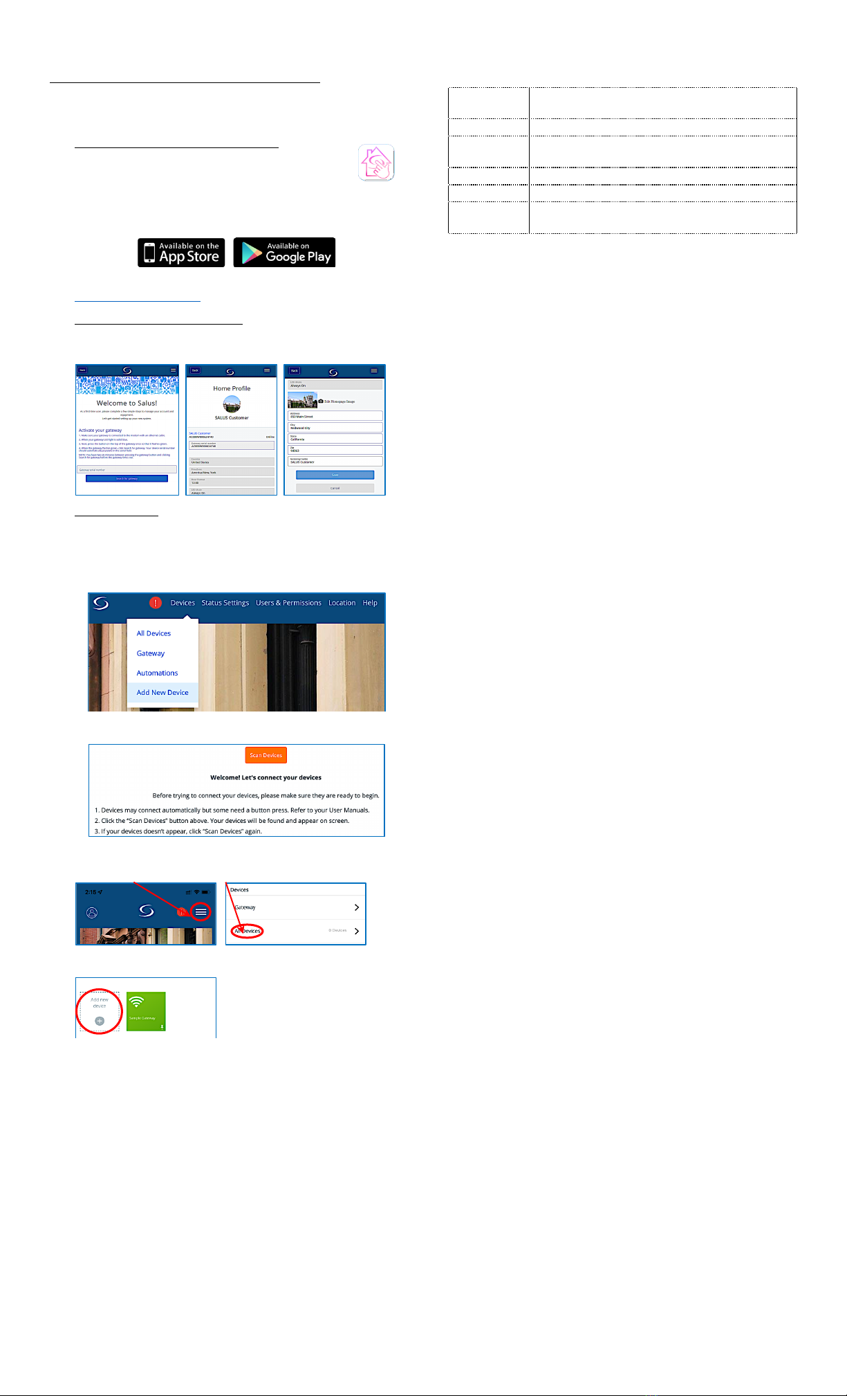
3. Add new devices
Once the Gateway has been Activated and Registered, you may
Scan for new devices to Add or Join to the network.
In the web App, from your laptop or PC, hover over Devices, in
the top menu bar and click on Add New Device
Then click Scan Devices
In the mobile App, tap:
The menu button, then the All Devices
On the next page tap Add new device +.
Follow the prompts to select and name the device(s).
TROUBLESHOOTING
Gateway LED ring is steady Red
• Check the Ethernet cable on both ends
• Check the activity lights on the internet router
Gateway LED ring does not turn Blue
• Check firewall settings, TCP Ports 80 & 443 and UDP Ports 55055 &
55056 must be open to inbound and outbound traffic
Devices will not Join or Pair
• Confirm device Joining Pairing instructions
• Add a Zigbee Router/Repeater to the network
• Relocate the Gateway or device
Devices lose connection after Pairing
• Force rejoin from the device
• Add a Zigbee Router/Repeater to the network
• Relocate the Gateway or device
SPECIFICATIONS
Operating
Conditions
32 – 104°F / 0 – 40°C
10 – 90% humidity (non-condensing)
Storage
-14 – 140 °F / -10 – 60°C
Protocols
Supported
ZigBee HA 1.2 profile
WiFi 802.11n
RF Freq.
2.4 GHz
Input voltage
120VAC ±10%, 60 Hz
Size
Ø 3.5” x 2.2” /
Ø 89 x 56 mm
FCC Statements
WARNING: Changes or modifications to this unit not expressly approved by the party responsible for
compliance could void the user’s authority to operate the equipment.
This device complies with Part 15 of the FCC Rules. Operation is subject to the following two conditions:
(1) this device may not cause harmful interference, and (2) this device must accept any interference
received, including interference that may cause undesired operation.
NOTE: This equipment has been tested and found to comply with the limits for a Class B digital device,
pursuant to Part 15 of the FCC Rules. These limits are designed to provide reasonable protection against
harmful interference in a residential installation. This equipment generates, uses and can radiate radio
frequency energy, and if not installed and used in accordance with the instructions, may cause harmful
interference to radio communications. However, there is no guarantee that interference will not occur
in a particular installation. If this equipment does cause harmful interference to radio or television
reception, which can be determined by turning the equipment off and on, the user is encouraged to try
to correct the interference by one or more of the following measures:
• Reorient or relocate the receiving antenna.
• Increase the separation between the equipment and receiver.
• Connect the equipment into an outlet on a circuit different from that to which the receiver is
connected.
• Consult the dealer or an experienced radio/TV technician for help.
FCC AND INDUSTRY CANADA
RF Radiation Exposure statement: !This equipment complies with FCC and Industry Canada RF
radiation exposure limits set forth for an uncontrolled environment. This equipment should be
installed and operated with a minimum distance of 20 centimeters between the antenna and all
persons.
INDUSTRY CANADA
This device complies with Industry Canada licence-exempt RSS standard(s). Operation is subject to the
following two conditions: (1) this device may not cause interference, and (2) this device must accept any
interference, including interference that may cause undesired operation of the device.
Le présent appareil est conforme aux CNR d'Industrie Canada applicables aux appareils radio exempts de
licence. L'exploitation est autorisée aux deux conditions suivantes : (1) l'appareil ne doit pas produire de
brouillage, et (2) l'utilisateur de l'appareil doit accepter tout brouillage radioélectrique subi, même si le
brouillage est susceptible d'en compromettre le fonctionnement.
SALUS WARRANTY
SALUS North America, Inc. (“Salus”) warrants that for a period of five (5) years (“Warranty Period”) from
the date of purchase by the consumer (“Customer”), this device, excluding batteries (“Product”), shall
be free of defects in materials and workmanship under normal use and service in accordance with all
supplied instructions. During the warranty period, Salus shall, at its option, repair or replace any
defective Products, at no charge for the device. Any replacement and/or repaired devices are warranted
for the remainder of the original Warranty Period or ninety (90) days, whichever is longer.
This warranty does not cover removal or reinstallation costs. This warranty does not apply to any Product
(i) which has been modified, repaired, or altered, except by Salus or an authorized Salus representative,
(ii) which has not been maintained in accordance with any handling or operating instructions supplied
by Salus, or (iii) which has been subjected to unusual physical or electrical stress, misuses, abuse,
negligence or accidents.
This warranty is the only express warranty Salus makes for the Product. Any implied warranties,
including warranties of merchantability or fitness for a particular purpose, are limited to the Warranty
Period or the shortest period allowed by law.
SALUS SHALL NOT BE LIABLE FOR ANY LOSS OR DAMAGE OF ANY KIND, INCLUDING ANY SPECIAL,
INCIDENTAL OR CONSEQUENTIAL DAMAGES RESULTING, DIRECTLY OR INDIRECTLY, FROM ANY BREACH OF
ANY WARRANTY, EXPRESS OR IMPLIED, OR ANY OTHER FAILURE OF THIS PRODUCT. Some states and
provinces do not allow the exclusion or limitation of incidental or consequential damages, or limitation
on the duration of implied warranties of merchantability or fitness, so these exclusions or limitations
may not apply to you.
No oral or written information or advice given by Salus or a Salus-authorized representative shall modify
or extend this warranty. If any term is held to be illegal or unenforceable, the legality or enforceability
of the remaining terms shall not be affected or impaired.
Customer’s sole and exclusive remedy under this limited warranty is product repair or replacement as
provided herein. If a Product under warranty is defective, the Customer may:
• contact the party (“Seller”) from which the Customer purchased the Product to obtain an
equivalent replacement product after the Seller has determined that the Product is defective and
the Customer is eligible for a replacement, or
• contact Salus Service at [email protected], to determine whether the device qualifies for a
replacement. If a replacement is warranted and is shipped prior to the return of the device under
warranty, a credit card is required and a hold may be placed on the Customer’s creditcard for the
value of the replacement until the returned device is verified as eligible for replacement, in which
case, the Customer’s credit card will not be charged.
This warranty gives you specific legal rights, and you may also have other rights that vary from
jurisdiction to jurisdiction. If you have any questions regarding this warranty, please write Salus at:
SALUS North America, Inc.
2215 Cornell Ave,
Montgomery, IL 60538
SMC-QG-SG888ZB_EN_2209v1
Copyright ©SALUS North America, Inc. 2022

Other manuals for SG888ZB

4

Other Salus Gateway manuals

Salus RE10RF User manual

Salus

Salus RE10RF User manual

Salus SAU2AG1 User manual

Salus

Salus SAU2AG1 User manual

Salus UGE600 User manual

Salus

Salus UGE600 User manual

Salus SG888ZB User manual

Salus

Salus SG888ZB User manual

Salus G30 User guide

Salus

Salus G30 User guide

Salus SG888ZB Operation manual

Salus

Salus SG888ZB Operation manual

Salus iTG310 User manual

Salus

Salus iTG310 User manual

Popular Gateway manuals by other brands

Cisco 3527 PRI G Installation and upgrade guide

Cisco

Cisco 3527 PRI G Installation and upgrade guide

Huawei B882-66 Quick start quide

Huawei

Huawei B882-66 Quick start quide

Fanvil A1 user manual

Fanvil

Fanvil A1 user manual

Westell VersaLink 327W user guide

Westell

Westell VersaLink 327W user guide

RTA 460ETCBC-NNA1 Product user guide

RTA

RTA 460ETCBC-NNA1 Product user guide

Sensus SensusRF user guide

Sensus

Sensus SensusRF user guide

ABB ARM600 quick start guide

ABB

ABB ARM600 quick start guide

M-system WL40EW2KR user manual

M-system

M-system WL40EW2KR user manual

Wieland gesis KNX FLEX-ENO32B installation instructions

Wieland

Wieland gesis KNX FLEX-ENO32B installation instructions

Alvarion BreezeACCESS SU-A-EZ product manual

Alvarion

Alvarion BreezeACCESS SU-A-EZ product manual

Top Global MB9000 Series user guide

Top Global

Top Global MB9000 Series user guide

Hoymiles DTU-Pro Quick installation guide

Hoymiles

Hoymiles DTU-Pro Quick installation guide

Allied Telesis AT-FH708E installation guide

Allied Telesis

Allied Telesis AT-FH708E installation guide

LG PHNFP14A0 installation manual

LG

LG PHNFP14A0 installation manual

Sangoma Vega 100G quick start guide

Sangoma

Sangoma Vega 100G quick start guide

Ruckus Wireless ZoneDirector ZD1100 Upgrade instructions

Ruckus Wireless

Ruckus Wireless ZoneDirector ZD1100 Upgrade instructions

RTA 460MSBS-NNA4 Product user guide

RTA

RTA 460MSBS-NNA4 Product user guide

Philips Dynalite PDZG-E installation instructions

Philips

Philips Dynalite PDZG-E installation instructions

manuals.online logo
manuals.online logoBrands
  • About & Mission
  • Contact us
  • Privacy Policy
  • Terms and Conditions

Copyright 2025 Manuals.Online. All Rights Reserved.