Salus HTRP-RF(50) User manual

HTRP-RF(50) THERMOSTAT - FULL USER MANUAL

TABLE OF CONTENTS
1. Introduction...............................................................................................................................................................5
1.1 Product Compliance ......................................................................................................................................................................5
1.2 Safety Informations.......................................................................................................................................................................5
2. Product Overview .......................................................................................................................................................6
2.1 Montage........................................................................................................................................................................................6
2.2 Package content............................................................................................................................................................................6
2.3 Proper thermostat location ...........................................................................................................................................................6
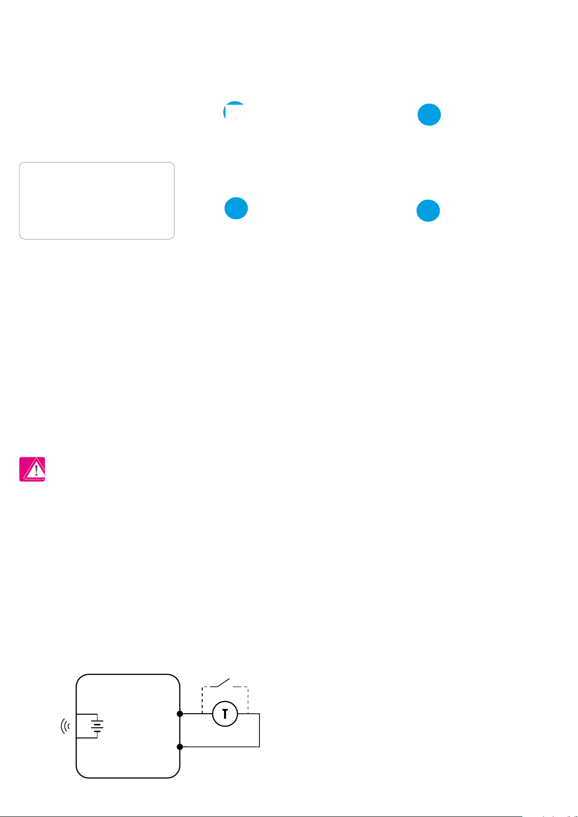
2.4 Connection Description (HTRP-RF(50) thermostat) .......................................................................................................................6
3. About ZigBee network ................................................................................................................................................7
3.1 ZigBee network - creation and work..............................................................................................................................................7
3.2 Compatibility with SALUS devices (ONLINE AND OFFLINE).............................................................................................................8
4. Before you start (rst power up) ..................................................................................................................................9
4.1 LCD icon description ......................................................................................................................................................................9
4.2 Button description.........................................................................................................................................................................9
4.3 First power up sequence and preparing to the pair process.........................................................................................................10
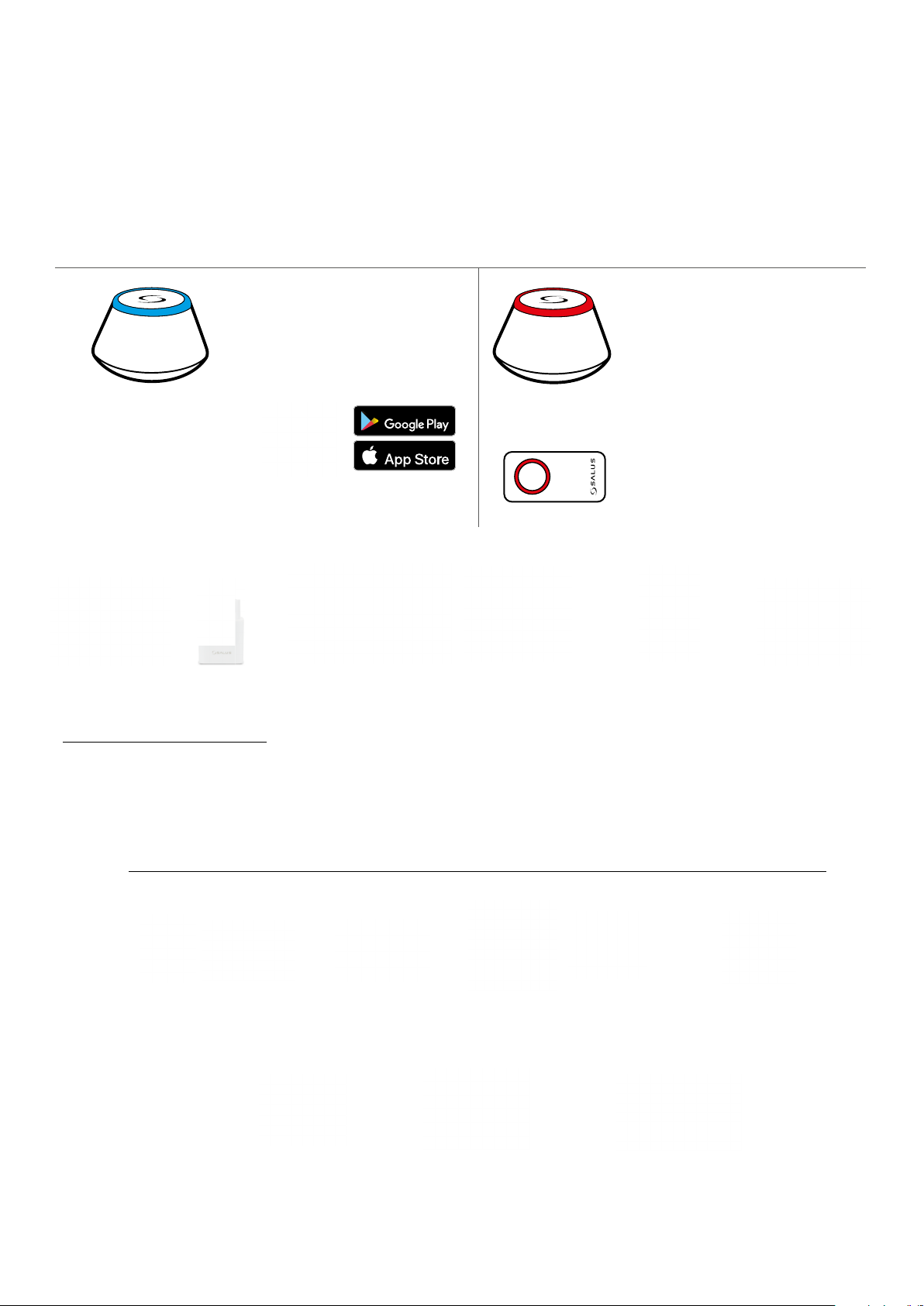
5. Installation by SALUS Smart Home application (ONLINE MODE).....................................................................................11
5.1 General informations about SALUS Smart Home application.......................................................................................................11
5.2 Pairing with underoor heating wiring centre (KL08RF/Control Box)..........................................................................................12
5.3 Pairing with wireless TRV radiator head ......................................................................................................................................15
5.4 Pairing with Smart Plug SPE600..................................................................................................................................................17
5.5 Pairing with Smart Relay SR600..................................................................................................................................................19
5.6 Pairing with RX10RF receiver.......................................................................................................................................................21
6. OPERATING in ONLINE MODE (by app) ..........................................................................................................................23
6.1 General informations...................................................................................................................................................................23
6.2 App icons description ..................................................................................................................................................................23
6.3 Change thermostat name (pencil icon) .......................................................................................................................................24
6.4 Setpoint temperature change .....................................................................................................................................................25
6.5 Heat/Cool mode change (KL08RF connection).............................................................................................................................26
6.6 Thermostat modes ......................................................................................................................................................................27
6.6.1 Schedule mode ..........................................................................................................................................................27
6.6.2 Temporary override mode..........................................................................................................................................31
6.6.3 Manual mode.............................................................................................................................................................31
6.6.4 Frost protection..........................................................................................................................................................32
6.7 Key lock function.........................................................................................................................................................................33
6.8 Compatibility with window/door sensor OS600 / SW600............................................................................................................34
6.9 Compatibility with Smart Plug SPE600........................................................................................................................................35
6.10 Compatibility with Smart Relay SR600......................................................................................................................................36
6.11 Identication mode...................................................................................................................................................................37
6.12 Pinning/unpinning thermostat to/from application dashboard ................................................................................................38
6.13 User settings (basic settings).....................................................................................................................................................39
6.14 Admin settings (installer parameters).......................................................................................................................................40
6.15 OneTouch rules (add/edit) ........................................................................................................................................................41
6.16 Error codes (exclamation mark in app) ......................................................................................................................................45
6.17 Wireless signal strength test......................................................................................................................................................46
6.18 Factory reset (removing thermostat from the app and ZigBee network)...................................................................................47

7. Installation in OFFLINE MODE without SALUS SmartHome application ..........................................................................49
7.1 General informations .................................................................................................................................................................49
7.2 Pairing with underoor heating wiring centre (KL08RF/Control Box)..........................................................................................50
7.2.1 Available operation modes.........................................................................................................................................50
7.2.2 Grouping - installation of the thermostat as a group controller - MASTER..................................................................53
7.2.3 Installation as a programmable thermostat...............................................................................................................54
7.2.4 Replace the zone assigned to another thermostat .....................................................................................................55
7.3 Pairing with wireless TRV radiator head ......................................................................................................................................56
7.4 Pairing with RX10RF receiver.......................................................................................................................................................58
8. OPERATING in OFFLINE MODE......................................................................................................................................59
8.1 Work modes ................................................................................................................................................................................59
8.2 Heat/cool mode change (KL08RF connection).............................................................................................................................60
8.3 User settings (basic settings).......................................................................................................................................................61
8.3.1 Schedule mode - programming schedule...................................................................................................................61
8.3.2 Time/Date ..................................................................................................................................................................63
8.3.3 Thermostat calibration...............................................................................................................................................64
8.3.4 Key lock function........................................................................................................................................................65
9. Installer parameters .................................................................................................................................................66
10. Factory Reset..........................................................................................................................................................68
11. Error codes (error codes description with possible solutions) ......................................................................................69
12. Cleaning and Maintenance ......................................................................................................................................72
13. Technical Informations ............................................................................................................................................72
14. Warranty ................................................................................................................................................................73


5
This product complies with the essential requirements and other relevant provisions of Directives 2014/53/EU and 2011/65/EU. The full text of the EU
Declaration of Conformity is available at the following internet address: www.saluslegal.com.
• Before starting installation work and before using the product, read the entire manual.
• The information contained in the instructions is essential for proper functioning.
• To avoid accidents resulting in personal injury and material damage, please follow all safety precautions, specied in this manual.
• The device should not be used by people with limited mental, sensory or mental abilities, without experience, of insucient knowledge as well as
children.
• Do not use an unassembled device (eg without a cover).
• The device may only be opened by a qualied person.
• Keep electrical devices out of the reach of children and ensure that they do not play with it. Children should not be left unattended. If necessary,
disconnect the control system for the entire room.
• Do not leave the packaging, cabinet, or any loose parts of the device unattended, as they pose a risk to children.
WARNING!
• Installation must be carried out by a qualied person with appropriate electrical qualications in accordance with standards and regulations in force in
the given country and in the EU.
• Never try to connect the device other than as described in the manual.
• Before assembly, repair or maintenance as well as during any connection works it is absolutely necessary disconnect the mains supply and make sure
that the terminals and electric wires are not live.
• The device may not be exposed to extreme temperatures, strong vibrations or subjected to mechanical shock.
• The device should not be used in unfavorable environmental conditions or in rooms where there is a concentration of ammable gases, fumes or dust.
WARNING!
• There may be additional protection requirements for the entire installation that the installer is responsible for maintaining.
1. Introduction
1.1 Product Compliance
1.2 Safety Informations
Care for the natural environment is of paramount importance to us. The awareness that we manufacture electronic devices obliges us
to dispose of used electronic components and devices safely. Therefore the company has received a registration number issued by the
Chief Inspector for Environmental Protection.The crossed out symbol the trash can on the product means that the product must not be
disposed of with ordinary waste containers. Sorting waste for recycling helps to protect the environment. It is the user’s responsibility
to surrender used equipment to a designated collection point for recycling waste from electrical and electronic equipment.

6
2.1 Montage
2.2 Package content
1) HTRP-RF(50) thermostat
2) 2x AA batteries
3) Short instructions
4) Mounting screws
2.3 Proper thermostat location
Please note:
Wall mounting
2.4 Connection Description (HTRP-RF(50) thermostat)
S1, S2 terminals:
- air or oor temperature sensor
- external volt-free contact to connect any ON/OFF switch or occupancy
sensor (Hotel card)
Symbols explanation:
S – volt-free contact
T – temperature sensor eg. FS300
Mounting: to mount thermostat you can use accesories included with the set (mounting screws). Remove back cover to mount the plate to the wall.
Now please insert the batteries inside the thermostat. After this just attach thermostat to the plate right into designed holes in the plate.
HTRP-RF(50) is a room temperature thermostat that is used for wireless control of iT600 series devices such as: KL08RF wiring centre, TRV
radiator valve and RX10RF boiler receiver. In combination with Universal Gateway UGE600 this regulator can be controlled over the Internet using SALUS
SmartHome app (Online mode). Without Internet connection (Oine mode) thermostat works locally, but its communication with other devices must be
done through the coordinating unit - CO10RF. Full version of the PDF manual instruction is available on the website www.salus-controls.eu
The ideal position to thermostat mounting is about 1,5m under oor level far from heating or cooling sources. Thermostat can’t be
exposed to sunlight or any extreme conditions like for example draft.
Because of re and explosion risk there is not allowed to use thermostat in atmosphere of explosive gases and ammable liquids (eg coal dust). In case
if any of listed dangers occur you have to use additional protection measures – anti-dust and explosive gases (tight cover) or prevent their formation.
Furthermore, thermostat can’t be used in condensation of water vapor conditions and be exposed to water action.
12
34
S2
S
S1
HTRP RF // HTRS RF
3V
2 x AA
2. Product Overview

7
3. About ZigBee network
3.1 ZigBee network - creation and work
ZigBee is a wireless network based on IEEE 802.15.4 standard and it’s communication takes place in the 2.4 GHz band. The network is based on a mesh
topology, which allows for a very large range and high reliability. The maximum range of direct communication between two network nodes (devices) is
about 100m in open space.
The devices included in the ZigBee network are divided into three types:
- coordinator - there can only be one such device in each network. It acts as a connection node for all devices;
- router (repeater) - this device is powered by 230VAC, with functionality similar to classic network routers, and it’s task is to forward data packets and
increase the range of the network;
- terminal device - battery powered, sends data to the coordinator (also through the router) to which it is connected. It is usually put to sleep
temporarily, which helps reduce energy consumption.
Built-in security in the ZigBee protocol (ISO-27001 and SSAE16 / ISAE 3402 Type II - SOC 2 certication) ensure high transmission reliability, detection and
removal of transmission errors, as well as connectivity between established priority devices.
Security measures include:
- devices authenticated using a unique key pair;
- encrypted communication between the mobile application and the device;
- data encryption - HTTPS encrypted usingTLS, UDP channel with AES-128 encryption;
- layered access control to prevent tampering with one device threatening the entire system.
The ability to work many devices at a short distance from each other was achieved through the use of radio transmission of the spread spectrum signal.
The main advantages of devices working in the ZigBee system are two-way communication and minimization of energy consumption, which in many
cases allows them to be powered from chemical cells (alkaline batteries).
Four Simple steps to create ZigBee network:
1. Coordinator Installation - Universal Gateway for
ONLINE and OFFLINE systems with internet application
or CO10RF for only OFFLINE systems without application.
2. Now - add any device you want powered 230VAC.
Note to locate it as near coordinator as possible.
3. Now you can increase range of ZigBee network
by adding more devices powered 230 VAC.
4. To extend your network you can add more battery
devices and accesories.

8
3.2 Compatibility with SALUS devices (ONLINE AND OFFLINE)
COMPATIBILTY WITH OTHER SALUS CONTROLS DEVICES
HTRP-RF(50) thermostat can work in ONLINE or OFFLINE mode.
At rst step you need to decide in which mode your thermostat will work.
ONLINE MODE OFFLINE MODE
Universal Gateway is
CONNECTED TO THE INTERNET
You can congure and use all your
devices in the Smart Home App
Download the Smart Home App
on your iOS or Android device
for remote access to your SALUS
equipment. SALUS
Smart Home
CO10RF Coordinator - You can use
standard ZigBee network coordinator
to install and use your devices.
Universal Gateway is NOT
CONNECTED TO THE INTERNET
You can use your devices locally
without the SmartHome App. Gateway
works in this mode as standard ZigBee
coordinator.
Compatibile devices:
KL08RF wireless wiring
centre for 8-zone
underoor heating.
KL04RFextension TRV
(Thermostatic
Radiator Valve) with
wireless communication.
RX10RF
receiver
SR600
Smart Relay
SPE600
Smart Plug
GET IT ON
Download on the
OR
Other SmartHome devices/accessories
Only with Online Mode
Water leak sensor
WLS600
Double/single OneTouch button
SB600/CSB600
Smoke detector
SD600
Window/door Sensor
SW600 or OS600
RS600
Roller shutter
RE600
ZigBee network signal repeater
(only with UGE600)
RE10RF
ZigBee network signal
repeater

9
Button Description
Button Function
OR
1. Increase or decrease setpoint temperature.
2. Increase or decrease Day, Clock, Timer, Party and Holiday.
3. Select installer parameter value.
OR 1. Mode selection.
2. Moving between parameters.
1. OK key: Short press to conrm selection.
2. Long press to save and exit.
3. When Main Screen – long press to enter the user settings.
+
Hold down these buttons to lock or unlock the keyboard.
+
Hold down these buttons for 3 SECONDS to enter installer parameter settings.
4. Before you start (rst power up)
4.2 Button description
4.1 LCD icon description
1. Comfort temperature
2. Standard temperature
3. Economic temperature
4. Automatic mode
5. PARTY mode
6. Holiday mode
7. Frost protection mode
8. Temperature unit
9. Heating mode ON
10. Gateway wireless connection
11. Internet connection indicator
12. Cooling mode ON
13. Manual mode / override temp.
14. Group controller
15. Current / set temperature
16. Lock function
17. AM / PM
18. Day indicator
19. Clock
20. Settings
21. Low battery indicator
22. External temperature sensor
23. Program number
21
22
23
1314151617181920
8
9
10
11
12
1 2 3 4 5 6 7

10
4.3 First power up sequence and preparing to the pair process
After that, thermostat will automatically power
up and start boot sequence...
Set your thermostat for underoor
heating or radiator heating by
„ ” or „ ”buttons.
Then conrm by button.
...it will display all icons...
...then thermostat will display the
software version.
Remove the protection foil and insert
2xAA batteries by removing back cover.
3
2
1
5
4

11
SALUS
Smart Home
GET IT ON
Download on the
3
2
5. Installation by SALUS Smart Home application (ONLINE MODE)
5.1 General informations about SALUS Smart Home application
Thanks to UGE600 Universal Gateway and SALUS Smart Home app system allows you to remote control of your heating system in any place you
are in the moment by smartphone, tablet or computer with Internet connection. Then you have also access to advanced functions of HTRP-RF(50)
thermostat. You can also create OneTouch rules to customize system to your needs.
1
First make sure that you have downloaded the Salus Smart Home App from the Google Play or App
Store. You will need to follow a few easy steps to create an account and then link your thermostat to the
Universal Gateway and to the App.
You can also access the web version on:
http://eu.salusconnect.io/
To begin the pairing process the Gateway should be plugged into the power supply and connected to the
Internet. Also, make sure that the UGE600 is added to your Salus Smart Home App. For the installation of
the Universal Gateway, please refer to the UGE600 manual on salus-manuals.com
Make sure that your UGE600 Universal Gateway is added to the App.
The LED of the Gateway should be steady blue. Then go to HTRP-
-RF(50) thermostat and begin paring process with the UGE600 and
add it to the App.

12
5.2 Pairing with underoor heating wiring centre (KL08RF/Control Box)
564
SALUS
SmartHome
Go to SALUS Smart Home app.
3
Now thermostat is looking for the
signal from the coordinator...
Open main menu. Select„Settings”. Now enter to the„Setup Equipment”.
Press„Scan for equipment”button.
7 8
App has started scanning...
1
2
For easier installation, please make sure you have already added underoor heating wiring centre (KL08RF/Control Box) to your ZigBee network (please
refer to the underoor heating wiring centre manual instruction).
Please note:
Set your thermostat for underoor heating
by„ ” or „ ” buttons. Then
conrm by button.
9
...Gateway has started ashing red and
searching for the thermostat...

13
Select your KL08RF/Control Box
added before.
Choose
„UFH Wiring Centre”option.
Thermostat is connected. Go to the
Smart Home app to congure it.
10
Select your thermostat and press
„Connect equipment”button.
Name your thermostat and go
„Next”...
Press gear icon.
11 12
13 14 15

14
After that thermostat will display
main screen.
You succesfully congured HTRP-
-RF(50) thermostat with KL08RF
Control Box.
3
Gateway stop ashing and turn to steady
blue color which means pair process has
been nished.
Press„Finish”button to end the set
up process in the app.
Choose„No”if you want to set your
own schedule later or„Yes”if default
now.
Select the zone which you want attribute to
your thermostat.
17 18
19 20
16

15
5.3 Pairing with wireless TRV radiator head
1
SALUS
SmartHome
Go to SALUS Smart Home app.
3
Now thermostat is looking for the
signal from the coordinator...
564
Open main menu. Select„Settings”. Now enter to the„Setup Equipment”.
Thermostat is connected. Go to the
Smart Home app to congure it.
Press„Scan for equipment”button.
7 8
App has started scanning...
2
For easier installation, please make sure you have already added wireless TRV radiator heads to your ZigBee network (please refer to the wireless TRV
radiator head manual instruction).
Please note:
Set your thermostat for radiators by
„ ” or „ ”buttons. Then conrm
by button.
9
...Gateway has started ashing red and
searching for the thermostat...

16
After that thermostat will display main screen.
You succesfully congured HTRP-RF(50)
thermostat withWireless TRV radiator head.
3
Gateway stop ashing and turn to steady blue
color which means pair process has been nished.
Press„Finish”button to end the set
up process in the app.
Choose„No”if you want to set your own
schedule later or„Yes”if default now.
Select your TRV radiator
head from the list.
Now choose Smart Radiator Control.
17
13 14 15
16
Select your thermostat and press
„Connect equipment”button.
Name your thermostat and go
„Next”...
Press gear icon.
10 11 12

17
5.4 Pairing with Smart Plug SPE600
1
SALUS
SmartHome
Go to SALUS Smart Home app.
3
Now thermostat is looking for the
signal from the coordinator...
564
Open main menu. Select„Settings”. Now enter to the„Setup Equipment”.
Press„Scan for equipment”button.
7 8
App has started scanning...
2
For easier installation, please make sure you have already added Smart Plug SPE600 to your ZigBee network (please refer to the Smart Plug SPE600
manual instruction).
Please note:
Set your thermostat for underoor heating
by„ ” or „ ” buttons. Then
conrm by button.
Thermostat is connected. Go to the
Smart Home app to congure it.
9
...Gateway has started ashing red and
searching for the thermostat...

18
After that thermostat will display main screen.
You succesfully congured HTRP-RF(50)
thermostat with Smart Plug SPE600.
3
Gateway stop ashing and turn to steady blue
color which means pair process has been nished.
Press„Finish”button to end the set
up process in the app.
Choose„No”if you want to set your own
schedule later or„Yes”if default now.
Select your Smart Plug from the list.
Now choose Smart Plug.
Select your thermostat and press
„Connect equipment”button.
Name your thermostat and go
„Next”...
Press gear icon.
10 11 12
17
16
13 14 15

19
5.5 Pairing with Smart Relay SR600
1
SALUS
SmartHome
Go to SALUS Smart Home app.
3
Now thermostat is looking for the
signal from the coordinator...
564
Open main menu. Select„Settings”. Now enter to the„Setup Equipment”.
Press„Scan for equipment”button.
7 8
App has started scanning...
2
For easier installation, please make sure you have already added Smart Relay SR600 to your ZigBee network (please refer to the Smart Relay SR600
manual instruction).
Please note:
Set your thermostat for underoor heating
by„ ” or „ ” buttons. Then
conrm by button.
Thermostat is connected. Go to the
Smart Home app to congure it.
9
...Gateway has started ashing red and
searching for the thermostat...

20
After that thermostat will display main screen.
You succesfully congured HTRP-RF(50)
thermostat with Smart Relay SR600.
3
Gateway stop ashing and turn to steady blue
color which means pair process has been nished.
Select your Smart Relay from the list.
Now choose Smart Relay.
Select your thermostat and press
„Connect equipment”button.
Name your thermostat and go
„Next”...
Press gear icon.
10 11 12
17
16
Choose„No”if you want to set your own
schedule later or„Yes”if default now.
13 14 15
Press„Finish”button to end the set
up process in the app.
This manual suits for next models
6
Table of contents
Other Salus Thermostat manuals

Salus
Salus VS20WRF User manual

Salus
Salus iT500 User manual

Salus
Salus ERT50T Triac User manual

Salus
Salus HTRS230 User guide

Salus
Salus 091FLRF User manual

Salus
Salus RTS00RF User manual

Salus
Salus RT310 User manual

Salus
Salus RT510 Service manual

Salus
Salus ST620ROF User manual

Salus
Salus HTR-RF(20) User manual