Setting Setpoint Temperature:
•Press or to enter Setpoint temperature
setting mode. The Setpoint temperature is
flashing to indicate that it can be changed.
• Release and press or again to increase or
decrease the Setpoint temperature by 0.5°C
resepectively.
• Hold or for another 2 seconds to enter fast
advance in 4Hz.
•The setting range is 10˚C-35°C in steps of 0.5°C.
Salus Controls plc
Enterprise Park, Bala
Gwyne dd, LL 23 7NL
Regional offices, England & Scotland.
Web: www.salus-tech.com
Email: sales@salu s- tech.co m
Sales +44 (0) 87 00 766900
Technical +44 (0) 87 00 7 66902
Maintaining a policy of continual product
development Salus Controls plc. reserve the right to
change specification, design and materials of
products listed in this brochure without prior notice.
Manual Issue No. IM-RT300-001
Digital Room
THERMOSTAT
In stru ct ion Ma nual
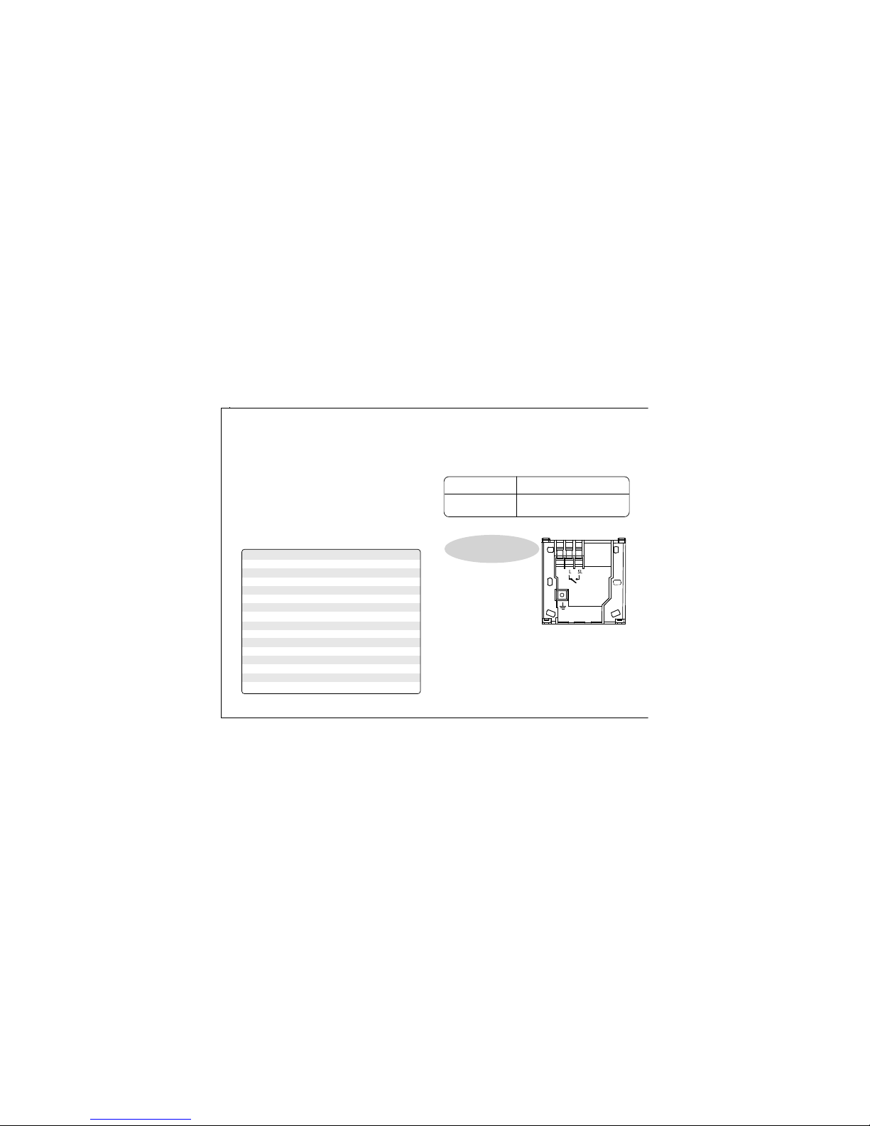
Terminal Name Function
L Live
SL Switched Live
Earth Parking
for Model No. RT300
Specification
PRIOR TO INSTALLING PLEASE
READ THE INSTALLATION GUIDE
The RT 300 is easily installed using the Industry
Standard back plate supplied which can be
mounted directly to the wall surface or a single
gang recessed box using the holes provided; cable
entry is from the rear.
The RT300 must be located where it would not be
subjected to extraneous heat gain/loss (such as
above radiators, direct sunlight or in draughts).
Normal household air circulation.
Switches/Jumpers:
Switch/Jumpers Function
Temperature Span 1 Jumper for +/-0.5°C (factory
default setting) or 1.0°C selection.
Back Plate & Wiring for the RT300
Terminals:
1 2 3 4
User Instructions
Initial Power Up:
• After power up or RESET is pressed, the
thermostat is reset.
• During system reset, all LCD segments are
turned on for 2 seconds.
After 2 seconds the thermostat is initialised.
The typical reset display is shown below.
5 6 7 8 9 10
Others:
•All flashing indications are 1Hz (0.5 second on,
0.5 second off).
• Temperature below 10°C is displayed without
the preceding "0".
• Temperature exceeding measurement range will
be indicated by "HI" for temperature exceeds
upper limit and "LO" for temperature exceeds
lower limit.
• Temperature sampling is performed every 15
seconds and is only in Normal mode.
• Battery status is sampled every minute in
Normal mode.
• Temperature and battery sampling will not be
performed when there has been any key
pressed in the last 10 seconds.
• Key debounce is implemented on both key
depress and release with duration longer than
20ms.
• Following table is the setting of the thermostat
after reset.
Function Status after Reset
Operation Mode Normal mode
Room Temperature 22.0°C, to be renewed
within 5 seconds
Setpoint Temperature 20.0°C
°C indicator On
Frost Protection indicator Off
Heat indicator Off
Low-Battery Warning Off, to be renewed
indicator within 5 seconds
Output Relay Off
After reset, the thermostat is operating at Normal
mode. Setpoint temperature is reset to default setting.
Room temperature is updated in 5 seconds and the
control process starts.
Reviewing Setpoint Temperature:
•Press or to review the Setpoint temperature.
•Press BL/FROST or wait
3 seconds without key
press to return to normal
operation, room
temperature will be
displayed.
• Setpoint Temperature will stop flashing when a
key is pressed, then flashes again once the key is
released.
• Thermostat will return to normal mode after 3-4
seconds if no key is pressed.
When Frost Protection is enabled, setting of
Setpoint temperature is prohibited.
Frost Protection:
•Press and hold BL/FROST for 3 seconds to
activate Frost Protection.
The Setpoint temperature is automatically set to 5°C
to prevent frosting.
Whenever the Frost Protection is activated, the Frost
Protection indicator is animating with the below
sequence in 4Hz
•Press BL/FROST for 3 seconds to de-activate the
Frost Protection, the Frost Protection indicator is
turned off.
LCD Backlight:
•LCD backlight is activated when BL/FROST or
any key is pressed. The backlight will
automatically turn off 5 seconds after all keys are
released.
•LCD backlight will not operate when battery is
low.
•LCD backlight isilluminated throughout the
Setpoint Temperature setting.
Low-Battery Detection:
Battery voltage is sampled every minute. When the
battery voltage drops to a certain level, the Low-
Battery warning indicator appears.
• The thermostat functions normally during
battery low. However, user must change the
batteries as soon as possible before they are
so weak that normal operation cannot be
assured.
• Battery voltage is determined as "low" when it is
less than or equal to 2.6V. It is determined as
normal when it is higher than or equal to 2.8V,
i.e.Low-Battery indicator must come out when
battery voltage is <= 2.6V, and must be turn off
when battery voltage is >= 2.8V.
• Battery voltage is only sampled in Normal mode
and when LCD backlight is turned off.
Sleep Mode:
•Press and hold and for 3 seconds
simultaneously to enter the Sleep mode.
•All the functions will be paused to save battery
power.
•The whole LCD will be blank.
• Output will be turned off immediately.
•Press any key to wake up the unit.
Thank you for purchasing this Salus product
- if installing for someone else, please ensure that
the instructions are handed to the householder.
Warning - Please read this manual prior to
installation or use.
Shock Hazard
This unit must be installed by a competent person,
in accordance with BS 7671 (the IEE Wiring
Regulations), or other relevant national regulations
and codes of good practise.
Always isolate the AC Mains supply before removing
the unit from the Industry Standard Back Plate.
The installer should select the jumper positionsrequired
if changing from the factory presets-these jumpers are
found on the rear of the unit.
1) Select a suitable location
noting the advice in page
1 of this manual, a suitable
mounting height is 1.5m
above FFL
2) Isolate AC mains supply,
note this must be 230 Vac
and fusedat 5 amps.
3) Optimum cable size is
1.5mm CSA; wiring colour
codes vary in different countries and are not defined here.
4) Enter cable to rear of back plate.
5) Securely fix back plate to wall surface or recessed back
box using holes provided.
6) Terminate conductors as per the wiring diagram on the
unit, ensuring conductors are firmly gripped beneath
square brass washer.
7) This appliance is Double Insulated and must not be
earthed except at the Earth Parking terminal provided.
8) The Industry Standard back plate has 6 holes in which to
fix to the surface of your choice. Please note that some
pressure downwards is required to lock the pins in the
Unit to connectors in the Back Plate, retain with the
captive screws at the bottom of the Back Plate taking care
not to over tighten.
9) Fit the batteries supplied and programme unit as desired,
restore AC mains to systemwhen all associated items are
fully installed and test for correct operation. NOTE: for
your convenience it is possible to install the batteries and
programme the unit prior to fitting to the wall.
This unit does
not require to be earthed, earth
terminal provided for safe
connection of all earth wires only.
Switch Rating : 230V/50Hz/3A
Switch Type : Single pole, single throw (SPST)
Power Supply : 2 x AA size Alkaline batteries
Operating Temperature : 0oC - 50oC
Temperature Setting Range : 10oC - 35oC in 0.5oC steps
Storage Conditions : -20oC - 55oC to 90% RH/non condensing
Frost Protection Temperature : 5oC
Battery Low Warning : 2.6 - 2.8V
Temperature Control Accuracy : +/- 0.5oC at 25oC
Operating Humidity : 0 to 90% RH/non condensing
Protection : Auto cut off at over 35oC
Memory : Memory hold up: 5 minutes
Back Light : EL Panel blue colour
Agency Approval
: CE
Micro Disconnection On Operation : Type 1.B control action
Rated Impulse Voltage : 4kV


 User manual")