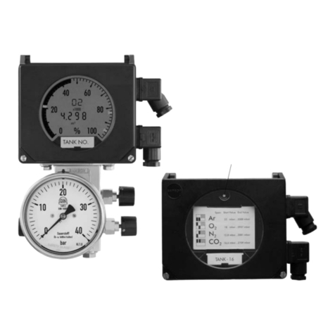
Samson Media 6 User manual

Operating Instructions
EB 9527-2 EN
Firmware: TROVIS-VIEW 4/Media 6 V3.10-3.19
Translation of original instructions
®
Electronics from SAMSON Edition February 2016
TROVIS-VIEW4 Software for Media6
Media6 Differential Pressure Meter
Conguration with TROVIS-VIEW4

Denition of signal words
DANGER!
Hazardous situations which, if not
avoided, will result in death or seri-
ous injury
WARNING!
Hazardous situations which, if not
avoided, could result in death or seri-
ous injury
NOTICE
Property damage message or mal-
function
Note:
Additional information
Tip:
Recommended action
2 EB 9527-2 EN

Contents
EB 9527-2 EN 3
1 TROVIS-VIEW4 software ...............................................................................5
1.1 General ........................................................................................................5
2 Communication with Media6 Differential Pressure and Flow Meter .................6
3 User interface ................................................................................................7
3.1 Liquid level measurement................................................................................7
3.1.1 Identication..................................................................................................8
3.1.2 General data.................................................................................................8
3.1.3 Tank............................................................................................................10
3.1.4 Medium ......................................................................................................14
3.1.5 Maintenance ...............................................................................................21
3.1.6 Certicates and approvals ............................................................................22
3.1.7 Operation ...................................................................................................23
3.2 Flow measurement, counting ow rate measurement, differential pressure mea-
surement, level measurement in transportation vehicles ...................................25
3.2.1 Flow rate measurement.................................................................................26
3.2.2 Counting ow rate measurement ...................................................................29
3.2.3 Differential pressure measurement .................................................................31
3.2.4 Level measurement in transportation vehicles..................................................33
3.3 Settings at the Media6 device ......................................................................34
3.3.1 Testing the limit switches and current output....................................................34
3.3.2 Zero and span calibration ............................................................................34
3.3.3 Zero point setting through basic calibration....................................................34
4 Data exchange ............................................................................................35
4.1 Read data from the Media6 device to TROVISVIEW4 ..................................35
4.2 Write data from TROVISVIEW4 to the Media6 device..................................36

4 EB 9527-2 EN

EB 9527-2 EN 5
TROVIS-VIEW4 software
1 TROVIS-VIEW4 software
These instructions describe the operation and setting of the Media6 Differential Pressure Me-
ter on the TROVIS-VIEW4 operator interface.
Refer to Mounting and Operating Instructions uEB9527-3 for a description of the Media6
Differential Pressure Meter.
Refer to the Operating Instructions uEB6661 on how to use the TROVIS-VIEW4 software.
The TROVIS-VIEW4 software allows users to congure and parameterize various smart
SAMSON devices (in this case, the Media6 Differential Pressure Meter) over a common user
interface. It consists of the operator interface, communication server, and the device-specic
module. It is possible to switch languages during operation (currently, English, German,
French, Spanish, Japanese, Russian, Danish available). Working in TROVIS-VIEW is similar
to working in Windows Explorer.
In addition to conguration and operation, the TROVIS-VIEW4 software includes other fea-
tures, such as documentation of the Media6 device, for example, editing plant texts, saving
and printing conguration data.
Almost the entire conguration of a Media6 device can be performed using the software.
The user level set to 'Maintenance technician' is used to congure the device. This level is set
by default and can be changed.
The TROVIS-VIEW4 software allows operation in ofine mode (device not connected to a
PC) or in online mode (device connected to a PC). This enables data to be changed in the de-
vice immediately, or they can be saved on the computer rst and downloaded later to the de-
vice on site.
Each smart SAMSON device has its own separate module that contains the device-specic
specications.
1.1 General
TROVIS-VIEW4 and the Media6 device are supplied with default data for lling level mea-
surement, in cases where no specications have been made by the customer.
Newly created data data can be saved to a le, which can be opened at anytime. A stored
TROVIS-VIEW le (*.tro) contains the conguration data and parameters of one single device
and can be transferred to the Media6 device after it has been connected to the computer.
Settings and readings of the software are described in these instructions.

6 EB 9527-2 EN
Communication with Media6 Differential Pressure and Flow Meter
To download conguration data from the software to the SAMSON memory pen or to up-
load data from the memory pen, a SAMSON modular adapter must be inserted into the seri-
al interface of the PC or laptop to connect the memory pen. See the Operating Instructions
uEB6661 for TROVIS-VIEW4 software.
When the Media6 device is not connected, the default settings are shown in
TROVIS-VIEW4. A TROVIS-VIEW4 le (*.tro) can be loaded and edited by selecting Open
in the File menu.
Note:
New records created in TROVIS-VIEW4 rmware version 3.00 or higher are not
compatible with earlier versions (e.g. rmware version 2.30).
2 Communication with Media6 Differential Pressure and Flow
Meter
To establish communication between the software and the Media6 device, the electrical con-
nection of the Media6 device must be performed as described in the Mounting and Operat-
ing Instructions uEB9527-3.
To establish communication, the serial interface of the computer must be connected to the se-
rial interface port of the Media6 device using the SAMSON connecting cable. Following
this, start TROVIS-VIEW4 and perform the basic settings. The Media6 device can be cong-
ured step-by-step using the start-up wizard.
Write protection switch on the Media6 device set to OFF.
Refer to the Operating Instructions uEB6661 on how to use the TROVIS-VIEW4 software.

EB 9527-2 EN 7
User interface
3 User interface
Start TROVIS-VIEW4 (Media6).
The interface appears with a menu bar and tool bar and the tree structure for Media6,
which includes all relevant parameters organized in folders and subfolders.
You only perform the settings needed for communication with a Media6 device.
−Identication
−General data
−Tank
−Medium
−Maintenance
−Certicates and approvals
−Operation
3.1 Liquid level measurement
By default, all settings in TROVIS-VIEW4 are automatically performed in the 'Maintenance
technician' user level in [Filling level mode].
In the 'Specialist' user level, [Flow rate mode], [Counting ow rate mode], [Differential pres-
sure mode], [Filling level in tank truck] can also be selected.

8 EB 9527-2 EN
User interface
3.1.1 Identication
Data relevant for unique identication of the Media6 device are shown. These details cannot
be edited.
[Identication]
Type Media6 Differential Pressure Meter (Type5006)
Version Firmware version
Addition Identier for different versions
Serial no. Serial number of the connected Media6 device
3.1.2 General data
They allow the settings relevant for a measuring procedure to be made by selecting options
from drop-down lists or by directly entering values.
[General data]

EB 9527-2 EN 9
User interface
'Filling limit reached' signal
Select either 'Overow' or 'Operating lling limit'.
Both values for these options are to be entered in [Medium] depending on the specied
tanks.
The bar graph blinks on the display when the adjusted limit is exceeded.
'Equalizing valve open' signal
When 'Yes' is selected, a signal is activated when the equalizing valve on the valve block be-
tween the (+) and (–) measuring lines (see uEB9527-3, Fig.4) is opened. 'OFF' appears
on the display of the device.
Limit switch type A1
For limit switch A1: select either 'Min. contact' or 'Max. contact' in the list.
− Min. contact: alarm1 is activated when the value falls below the limit.
− Max. contact: alarm1 is activated when the value exceeds the limit.
Alarm limit A1 in %
Enter the value in the range between 0 and 100%.
A blinking bar graph on the display indicates that the adjusted value has been exceeded
(with a max. contact) or the value has fallen below the adjusted value (with a min. contact).
Limit switch type A2
For limit switch A2: select either 'Min. contact' or 'Max. contact'.
−Min. contact: alarm2 is activated when the value falls below the limit.
−Max. contact: alarm2 is activated when the value exceeds the limit.
Alarm limit A2 in %
Enter the value in the range between 0 and 100%.
A blinking bar graph on the display indicates that the adjusted value has been exceeded
(with a max. contact) or the value has fallen below the adjusted value (with a min. contact).
LCD·'On'/'Off'
The display can be turned on or off.
Power-saving mode (PSM)·'On'/'Off'
Select 'On' to place the measuring cycle and display into the power saving mode (ESM). The
charging state of the battery is indicated in [Status] > [Battery voltage] (see [Status],
page24).

10 EB 9527-2 EN
User interface
3.1.3 Tank
Certain data about the tank shape must be known to calculate tank characteristic. A default
set of data with predetermined values is available in the tank database. Load these data and
overwrite them with the corresponding tank geometry data and settings.
[Tank]
Enter the geometrical data required to calculate the tank and its characteristic.

EB 9527-2 EN 11
User interface
[Identier]
A maximum of 15 characters can be entered to describe the type of tank or the tank ID. The
text appears in upper-case letters.
The tank ID runs across the display of the Media6 device.
[Tank database]
[Load data
You can load and modify existing tank geometrical data from the database.
[Save data
Save newly entered or changed tank data to Media database.
[Tank type/shape]
Tank type·Drop-down list with four entries:
−Cylinder, upright
−Cylinder, horizontal
−Ball
−Characteristic mode
Dene tank geometry by selecting the corresponding entry.
Shape of tank bottom·Drop-down list with ve entries:
−Flat head
−Torispherical bottom
−Semi-ellipsoidal bottom
−Enter r and R
−Enter R (r=0)
[Inside tank dimensions]
Existing data·Drop-down list with three entries
−Diameter and length/height
−Length/height and volume
−Diameter and volume
After entering the data, TROVIS-VIEW4 automatically calculates the missing tank data and
displays them.
Diameter [di] in m
Inside tank diameter
Length L/H [L] in m
Length or height of the tank, depending its position (horizontal/upright)

12 EB 9527-2 EN
User interface
Static column [H] in m
Max. possible liquid column. This corresponds to the inside length (horizontal tank) or inside
height (upright tank). The value is automatically calculated.
Total volume [V] in m³
Corresponds to the geometric tank volume (gross useable tank volume in m³). The value is
automatically calculated, provided it has not been entered (existing data).
[Tank measuring line]
Length/height [Hs] in m
Length of measuring line or pipe socket below the tank. Input 0.000 to 5.000m.
[Reference volume (MCN = max. capacity nominal, SCN = safe capacity nominal)]
The volume at 20mA corresponds to the tank MCN or to the gauge pipe marker SCN.
Select from toggle eld:
−Max. tank content (MCN)
−Tank content up to overow/gauge pipe (SCN)
Permissible lling limit in %
Geometric volume up to the overow in relation to the geometric tank capacity in percent;
e.g. 95%.
Permissible height [hperm] in m
Permissible height up to the gauge pipe or overow.
Permissible volume [Vperm.] in m³
Permissible volume. Corresponds to 'Total volume x [Permissible lling limit/100'.
Note:
If one of the values for lling limit, height, or volume is changed, the other two values
are automatically recalculated.
[Characteristic]
Indicates the tank characteristic, taking into account the tank geometry. The pairs of values
consist of the tank volume V in m³ and the associated tank height H in mm.

EB 9527-2 EN 13
User interface

14 EB 9527-2 EN
User interface
3.1.4 Medium
[Medium]
The data for a maximum of four media can be entered.

EB 9527-2 EN 15
User interface
[Medium1] to [Medium4]
−Medium database
−General medium data
−Tank pressure
−Density calculations
−Densities
−Operating lling limit, hazard warning
−Calculated values
[Medium database]
[Load data
You can load and modify existing media data from the database.

16 EB 9527-2 EN
User interface
[Save data
Save newly entered or changed tank data to Media database.
[General medium data]
−Medium identier
−Unit
−Shrink factor
Medium identier
A maximum of 8 characters can be entered to describe the tank content (stored medium). The
text appears in upper-case letters on the display of the Media 6 device.
Unit·Drop-down list with six entries
−m³, %, kg, L, ft³, lbs
Shrink factor
Enter the shrink factor valid at the operating temperature of the tank. This value depends on
the tank material, operating temperature, and the process medium.
[Tank pressure]
−Additional pressure
−Operating pressure
−Unit of 'Operating pressure'
Additional pressure·Yes/No
Select 'Yes' to show 'Operating pressure' under PTANK on the display of the Media6 device.
Operating pressure in bar
Enter the actual absolute pressure applied to the tank (usually the air pressure).
Unit of 'Operating pressure'·Drop-down list with eight entries
−mbar, bar, kPa, psi, mmH2O, cmH2O, mH2O, inH2O
[Density calculations]
When 'By medium data' is selected
−Data logging
−Gas column correction
Data logging·By medium data/By preset pressure

EB 9527-2 EN 17
User interface
Medium data
Enter the gas column correction as well as the liquid density and mixture density (see [Densi-
ties]).
Gas column correction·Yes/No
Yes·The gas column correction increases the accuracy of the lling level indication. It can
only be performed if the gas density in the tank and in the low-pressure pipe are known.
Therefore, enter the density after activating the gas column correction (see [Density]).
No·No values need to be entered in 'Gas density in the tank' and 'Gas density in the
low-pressure pipe'.
When 'By preset pressure' is selected
−Min. differential pressure
−Max. differential pressure
−Final reference value
By preset pressure
The minimum and maximum differential pressure as well as nal reference value must be en-
tered.
Minimum differential pressure in mbar
Pressure at 0% reading (= 4mA).
Maximum differential pressure in mbar
Pressure at 100% reading (= 20mA).
Final reference value in m³
Value displayed at 100% tank content.
[Densities]
−Liquid density
−Standard gas density
−Gas density in tank
−Gas density in low-pressure pipe

18 EB 9527-2 EN
User interface
Liquid density in m³
Density of medium at 1bar (abs) and boiling temperature. To improve the accuracy of the in-
dicated lling level, enter the liquid density at operating conditions. In this case, the operat-
ing pressure density must be entered and changed manually (see [Operating pressure]). This
makes the lling level reading more precise.
Standard gas density in m³
Gas density at 1 bar (abs) and 15°C. The current values for liquid density, gas density in the
tank, and gas density in the low-pressure pipe are automatically converted and displayed.
Gas density in tank and Gas density in low-pressure pipe in m³
−Details on gas column correction
Gas density in the tank depends on the nominal pressure and assumed temperature in the
tank. Gas density in the low-pressure pipe depends on the nominal pressure and assumed
temperature in the pipe.
Note:
The gas density in the tank and in the low-pressure pipe are required for gas column
correction of the content reading. If no correction is required, set both densities to 0.
Mixture density in m³
Mixture density refers to the density when lling the tank. The operating lling limit is derived
from this. It is automatically calculated on entering the liquid density.

EB 9527-2 EN 19
User interface
[Operating lling limit, hazard warning]
−Operating lling limit
Operating lling limit in %
A blinking bar graph element on the display indicates when the operating lling limit has
been reached.
A marking can be xed in the range between 0% and 95%. This is used to calculate the
tank content.
The blinking bar graph element serves as guide for the operator lling the tank.
[Calculated values]
Reading of the previously entered value and the automatically calculated value. It cannot be
edited and is only shown on the software.
−Max. tank content [MCN]·Entered in m³
−Tank content up to overow/gauge pipe [SCN]·Entered in m³
−Tank content up to 'Operating lling limit' [UCW]·Entered in m³
−Minimum differential pressure [Δp0]·Differential pressure in mbar at 0% lling level
−Maximum differential pressure [Δp100]·Differential pressure in mbar at 100% lling
level
Filling level table·Displays a table with lling levels corresponding to the tank data and
selected dimension.

20 EB 9527-2 EN
User interface
[Save ...]
The data can be saved to a le (.txt), e.g. lling level_01.txt, and processed on a computer
using other standard software.
Other manuals for Media 6
2
Table of contents
Other Samson Measuring Instrument manuals

Samson
Samson Media 7 Service manual

Samson
Samson 2100 Series Troubleshooting guide

Samson
Samson Media 05 Service manual

Samson
Samson 024.85 User manual

Samson
Samson 2162 Operating manual

Samson
Samson Media 6 Z Technical document

Samson
Samson Media 6 Service manual

Samson
Samson D-150 User manual

Samson
Samson Media 6 Service manual

Samson
Samson 411 110 Operating manual