1 Design and principle of operation
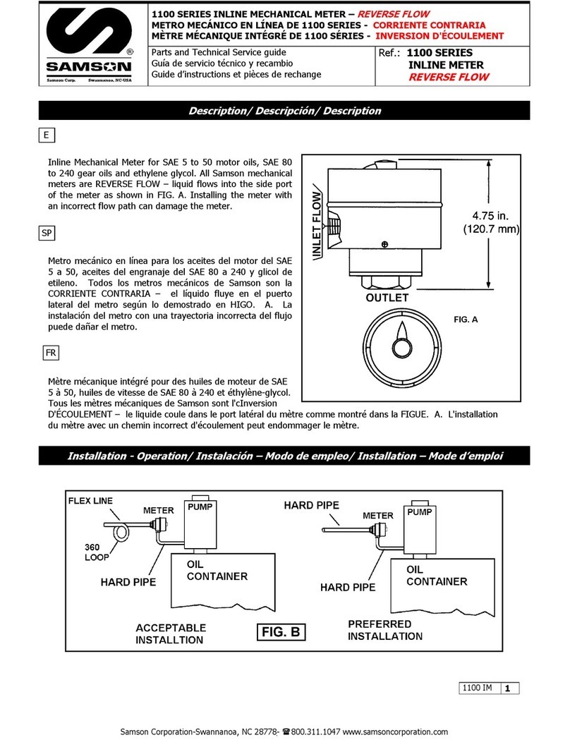
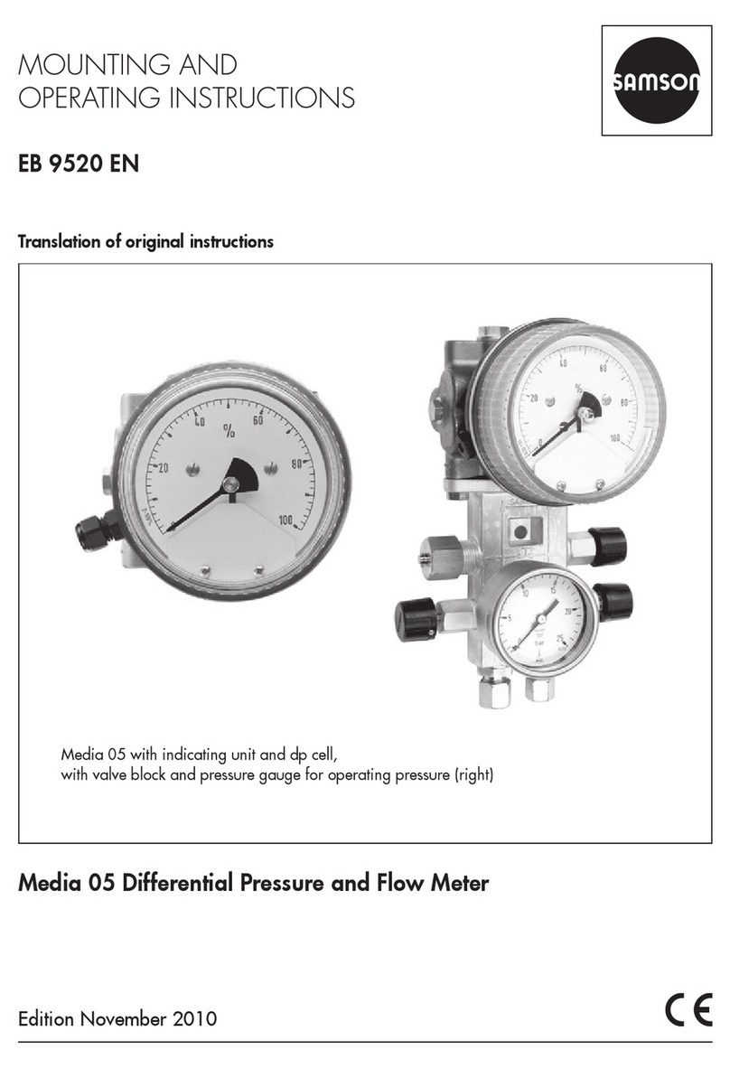
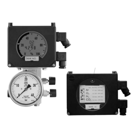
The Media 6 Differential Pressure Meters are
used to measure and indicate differential
pressure as well as derived measured
variables for gases and liquids.
Measuring tasks
–Liquid level measuring on pressure ves-
sels, particularly suitable for cryogenic
liquefied gases
–Differential pressure measuring between
flow and return flow pipe
–Pressure drop measuring on valves and
filters
– Flow rate measuring based on differential
pressure method
The device consists of the dp cell with measur-
ing diaphragm, measuring springs that
match the measuring range as well as the in-
dicating unit equipped with an LCD to indi-
cate certain operating states.
The differential pressure Δp=p
1–p
2gener-
ates a force on the measuring dia-
phragm (1.1), which is balanced by the mea-
suring springs (1.2). The movement of the
measuring diaphragm and lever (1.3), which
is proportional to the differential pressure, is
led out of the pressure chamber over the elas-
tic disc (1.4) and converted into an electric
signal by the travel sensor (2).
Evaluating the data saved in the FRAM (4),
the electric signal is processed by a micropro-
cessor (3). The microprocessor controls both
the display (7) and D/A converter (9) for the
output signal, which is issued asa4to20mA
two-wire transmitter signal at connector A.
The serial interface (10) allows the device to
be configured with the help of SAMSON's
TROVIS-VIEW Configuration and Operator
Interface using a special memory pen or a ca-
ble connection to a PC.
The user-specific data are saved in the mem-
ory (FRAM) (4) until they are overwritten
again. Data can also be backed up. As a re-
sult, the operating data can easily be ex-
changed on site between Media 6 and the
memory pen, and vice versa.
The memory pen can be programmed using a
PC and SAMSON's TROVIS-VIEW software.
The operating data allow the differential
pressure to be converted into values propor-
tional to the tank capacity or flow rate1); these
values are displayed or issued asa4to
20 mA DC signal.
Using the DIP switches (6), four saved gas
types and different write protection functions
for saved data can be selected.
Three operating keys (5) are used to adjust
different operating functions (zero and span
adjustment, filling limit during operation, limit
switch and test function settings etc.) as well
as set different operating states (load or save
operating values).
8EB 9527-3 EN
Design and principle of operation
1) Count pulses in Media 6 Z

