Samson Media 05 Service manual

Translation of original instructions
EB 9520 EN
Media 05 with indicating unit and dp cell,
with valve block and pressure gauge for operating pressure (right)
Edition November 2010
Media05 Differential Pressure and Flow Meter

Note on these mounting and operating instructions
These mounting and operating instructions assist you in mounting and operating the device
safely. The instructions are binding for handling SAMSON devices.
ÎFor the safe and proper use of these instructions, read them carefully and keep them for
later reference.
ÎIf you have any questions about these instructions, contact SAMSON‘s After-sales Service
Department (aftersalesser[email protected]).
The mounting and operating instructions for the devices are included in
the scope of delivery. The latest documentation is available on our website
at www.samson.de > Service & Support > Downloads > Documentation.
Denition of signal words
Hazardous situations which, if not avoided,
will result in death or serious injury
Hazardous situations which, if not avoided,
could result in death or serious injury
Property damage message or malfunction
Additional information
Recommended action
DANGER
!
WARNING
!
NOTICE
!
Note
Tip
2 EB 9520 EN

Contents
EB 9520 EN 3
1 Safety instructions and measures ...................................................................4
1.1 Notes on possible property damage................................................................7
2 Design and principle of operation ..................................................................8
2.1 Technical data .............................................................................................10
3 Installation..................................................................................................12
3.1 Arrangement of instruments for liquid level measurement ................................12
3.2 Arrangementofdevicesforowratemeasurement.........................................12
3.3 Media05indicatingunit ..............................................................................12
3.4 Differential pressure lines..............................................................................14
3.5 Oriceange(oriceplateassembly)............................................................14
4 Accessories .................................................................................................16
4.1 Valve block..................................................................................................16
4.2 Shut-off and equalizing valves ......................................................................16
4.3 Compensation chambers ..............................................................................16
4.4 Accessories for connection............................................................................16
5 Start-up ......................................................................................................18
5.1 Flow rate measurement.................................................................................18
5.2 Liquid level measurement..............................................................................18
6 Operation...................................................................................................19
6.1 Checking zero .............................................................................................19
6.2 Water drainage...........................................................................................19
6.3 Adjusting and modifying the measuring range ...............................................20
7 Version with limit contacts............................................................................22
7.1 Electrical connection.....................................................................................22
7.2 Adjusting the alarm contacts.........................................................................22
7.3 Retrottingorreplacingthecontactunit .........................................................24
8 Dimensions .................................................................................................26

4 EB 9520 EN
Safety instructions and measures
1 Safety instructions and measures
Intended use
The Media 05 Differential Pressure and Flow Meter is used to measure and indicate the dif-
ferential pressure or derived measuring variables for gases and liquids. Typical application
include liquid level measurement on pressure vessels, differential pressure measurement be-
tweenowandreturnowpipes,pressuredropmeasurementonvalvesandltersaswellas
owratemeasurementaccordingtothedifferentialpressuremethod.
Thedeviceisdesignedtooperateunderexactlydenedconditions(e.g.operatingpressure,
process medium, temperature). Therefore, operators must ensure that the device is only used
inoperatingconditionsthatmeetthespecicationsusedforsizingthedeviceattheordering
stage.
Incaseoperatorsintendtousethedeviceinotherapplicationsorconditionsthanspecied,
contact SAMSON.
SAMSON does not assume any liability for damage resulting from the failure to use the de-
vice for its intended purpose or for damage caused by external forces or any other external
factors.
ÎRefertothetechnicaldataforlimitsandeldsofapplicationaswellaspossibleuses.
The Media 05 Differential Pressure and Flow Meter without limit contacts may be used to
measureammablegasesandliquidsinwhichhazardousareaconditionsofZone0areto
be expected, provided the operator observes the applicable regulations for measuring
ammablegasesandliquidsinZone0.Thismeansthatmeasuringinstrumentsuitedforthe
connectiontoZone0canbeinstalledprovided:
1. The pipes connecting the instruments have been sized and installed according to the
German Technical Regulations for Flammable Liquids TRbF 50 or
2. Flamearrestersorenduranceburningamearrestershavebeeninstalledinthetwo
measuring lines.
Whetheryouhavetoinstallamearrestersorenduranceburningamearrestersdepends
ontheconditionsonsite.However,enduranceburningamearrestersarepreferablytobe
installed. You are required to contact the appropriate regulatory authority to agree on the
necessary measures.
Theoperatorisresponsibleformeetingtheabovespeciedrequirementsspecied(1and2).
SAMSON does not assume any responsibility if the operator fails to do so.

EB 9520 EN 5
Safety instructions and measures
Notes concerning oxygen service
Devices intended to measure gaseous oxygen are labeled
Oxygen! Keep free of oil and grease!
These versions are cleaned and assembled under special conditions. When replacing parts
that come into contact with gaseous oxygen, e.g. range springs, wear suitable gloves and
make sure that the parts do not come into contact with oil or grease.
When returning devices for oxygen service for repair, the sender assumes full responsibility
thatthedevicesarehandledtomeetallrequirementsstipulatedbyVBG62orsimilarregula-
tions until they are handed over to the manufacturer. Otherwise, SAMSON does not accept
any responsibility.
Reasonably foreseeable misuse
TheMedia05DifferentialPressureandFlowMeterisnot suitable for the following applica-
tions:
−Useoutsidethelimitsdenedduringsizingandbythetechnicaldata
Furthermore,thefollowingactivitiesdonotcomplywiththeintendeduse:
−Use of non-original spare parts
−PerformingmaintenanceactivitiesnotspeciedbySAMSON
Qualications of operating personnel
Thedevicemustbemounted,startedupandservicedbyfullytrainedandqualiedperson-
nel only; the accepted industry codes and practices are to be observed. According to these
mounting and operating instructions, trained personnel refers to individuals who are able to
judge the work they are assigned to and recognize possible hazards due to their specialized
training, their knowledge and experience as well as their knowledge of the applicable stan-
dards.
Personal protective equipment
We recommend wearing the following protective equipment depending on the process medi-
um:
−Protective clothing, gloves, eye protection and respiratory protection in applications with
hot, cold and/or corrosive media
ÎCheck with the plant operator for details on further protective equipment.

6 EB 9520 EN
Safety instructions and measures
Revisions and other modications
Revisions,conversionsorothermodicationsoftheproductarenotauthorizedbySAMSON.
They are performed at the user's own risk and may lead to safety hazards, for example.
Furthermore, the product may no longer meet the requirements for its intended use. Use of
the device is no longer permitted.
Warning against residual hazards
To avoid personal injury or property damage, operators and operating personnel must pre-
vent hazards that could be caused in the device by the process medium and operating pres-
sure by taking appropriate precautions. They must observe all hazard statements, warning
and caution notes in these mounting and operating instructions, especially for installation,
start-up and service work.
Responsibilities of the operator
The operator is responsible for proper operation and compliance with the safety regulations.
Operators are obliged to provide these mounting and operating instructions to the operating
personnel and to instruct them in proper operation. Furthermore, the operator must ensure
that operating personnel or third persons are not exposed to any danger.
Responsibilities of operating personnel
Operating personnel must read and understand these mounting and operating instructions as
wellasthespeciedhazardstatements,warningandcautionnotes.Furthermore,theoperat-
ing personnel must be familiar with the applicable health, safety and accident prevention
regulations and comply with them.
Referenced standards and regulations
DeviceswithaCEmarkingfullltherequirementsoftheDirective2014/30/EU.TheEU
declaration of conformity is included at the end of these instructions.
Referenced documentation
Thefollowingdocumentsapplyinadditiontothesemountingandoperatinginstructions:
−Mounting and operating instructions for mounted pipeline valves (strainers, shut-off
valves etc.)

EB 9520 EN 7
Safety instructions and measures
1.1 Notes on possible property damage
NOTICE
!
Notes concerning oxygen service
ÎDevices intended to measure gaseous oxygen are labeled
Oxygen! Keep free of oil and grease!
These versions are cleaned and assembled under special conditions. When
replacing parts that come into contact with gaseous oxygen, e.g. range springs,
wear suitable gloves and make sure that the parts do not come into contact with oil
or grease.
ÎMake sure that the dp cell and all SAMSON accessories only come into contact with
gaseous oxygen.
ÎWhen returning devices for oxygen service for repair, the sender assumes full
responsibility that the devices are handled to meet all requirements stipulated by
VBG62orsimilarregulationsuntiltheyarehandedovertothemanufacturer.
Otherwise, SAMSON does not accept any responsibility.
Risk of damage to the differential pressure and ow meter due to impermissible
negative pressure (vacuum) in the measuring chambers.
A negative pressure in the measuring chambers is not permissible during operation.
ÎThefollowingapplies:operating pressure ≥ atmospheric pressure.
A vacuum in both measuring chambers for a brief period of time, e.g. to clean tanks,
is permissible.
Incorrect operation in cryogenic applications will damage the differential pressure
and ow meter and will lead to malfunction.
In cryogenic applications, the process medium circulates during measurement when
the equalizing valve is opened, causing the valve block to ice up.
ÎDuring measurement, the equalizing valve must be closed and the shut-off valves
open.

8 EB 9520 EN
Design and principle of operation
2 Design and principle of
operation
The Media 05 Differential Pressure and Flow
Meter is used to measure and indicate the
differential pressure or derived measuring
variables for gases and liquids. Typical
application include liquid level measurement
on pressure vessels, differential pressure
measurementbetweenowandreturnow
pipes, pressure drop measurement on valves
andltersaswellasowratemeasurement
according to the differential pressure
method.
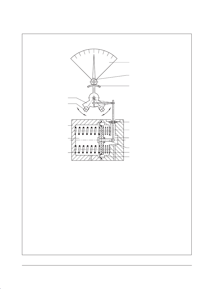
The device comprises a differential pressure
cell including a measuring diaphragm and
range springs as well as an indicating unit
including a pointer mechanism and dial
plate.
Thedifferentialpressure∆p=p1–p2
producedattheoriceplatecreatesaforce
at the measuring diaphragm (1.5), which is
opposed by the range springs (1.4).
The movement of the measuring diaphragm
and lever (1.8), which is proportional to the
differential pressure, is routed from the pres-
surechamberbyaexibledisk(1.9)and
transmitted to the pointer mechanism (2.2).
The differential pressure is shown linear on
thedialandtheowrateisshownasa
square root graduation.
Version with limit contacts
The gear segment (2.1) supports the metal
tags (3.1) and activates the alarm contacts
by moving the metal tags into the adjustable
proximity switches (3.2).
Whenthemetaltagenterstheinductiveeld
of the associated proximity switch, it as-
sumes a high resistance (contact open).
When the metal tag leaves the inductive
eld,itassumesalowresistance(contact
closed).
The switching function is triggered when the
metal tag leaves or enters the proximity
switches (depending on the setting of the
contacts).

EB 9520 EN 9
Design and principle of operation
2.3
2.2
2.1
3.1
3.2
A1 A2
1.1
1.3
1.4
1.9
1.8
1.2
1.
7
1.6
1.5
_
+
Differential pressure cell
1.1 dp cell
1.2 High-pressure chamber
1.3 Low-pressure chamber
1.4 Range springs
1.5 Measuring diaphragm
1.6 Diaphragm plates
1.7 Diaphragm stem
1.8 Lever
1.9 Flexible disk
Housing of indicating unit
2.1 Gear segment
2.2 Pointer mechanism
2.3 Dial plate
Limit contact (alarm contact)
3.1 Metal tag
3.2 Proximity switches for alarm contacts A1
and A2
Fig.1: Functional diagram: version with two alarm contacts

10 EB 9520 EN
Design and principle of operation
2.1 Technical data
All pressure in bar (gauge); all errors and deviations are specied in % of the adjusted mea-
suring span.
Media05 Differential Pressure and Flow Meter
Nominal range mbar 0 to
60
0 to
100
0 to
160
0 to
250
0 to
400
0 to
600
0 to
1000
0 to
1600
0 to
2500
0 to
3600
Adjustable
measuring span
(mbar)
Max. 40
to
66
60
to
110
100 to
176
160 to
275
250 to
440
400 to
660
600 to
1100
1000
to
1760
1600
to
2750
2500
to
3960Min.
Accuracy class in % ±4 ±2.5
Pressure rating PN 50, overloadable on one side up to 50 bar
Indicator 250°scale,approx.162mmscalelength,0to100%linearorsquare
root scale division for any linear measured variable, for measured
variables based on equations, curve or table
Characteristic Characteristic linear to differential pressure, scale linear to tank
content
Deviation from terminal-
based linearity <±2.5%1) (including hysteresis)
Sensitivity <0.25%(with0to60mbarnominalrange:<0.5%)
Effect of static pressure <0.03%/1bar<0.5%
Limit contacts TwoinductivealarmcontactsA1andA2acc.toEN60947-5-6
Control circuit Valuescorrespondingtoconnectedisolatingswitchampliere.g.
KFA6-SR2-Ex2.W
Proximity switch SJ2-SN, for hazardous areas according to PTB 00 ATEX 2049 X
Switching accuracy <±2%
Dead band, approx. <0.6%
Perm. ambient temperature –40to+80°C;foroxygen–40to+60°C
Perm. storage temperature –40to+100°C
When used with gaseous
oxygen as the process
medium
Max.temperature:+60°C·Max.oxygenpressure:30bar
Note

EB 9520 EN 11
Design and principle of operation
Degree of protection IP54accordingtoVDE0470-1/EN60529
Weight, approx. 2.6kgwithoutvalveblock·4.6kgwithvalveblock
Materials
Version Standard version
Housing Brass (CW617N) or CrNi steel
Measuring diaphragm and
seals ECO2)
Springs, diaphragm plates,
functional parts, lever CrNi steel
Housing of indicating unit Polycarbonate
1) Based on upper measuring range value
2) Other on request

12 EB 9520 EN
Installation
3 Installation
3.1 Arrangement of
instruments for liquid level
measurement
In arrangements as illustrated in the second
schematic drawing, the additional height z is
included in the measurement. As a result,
this height must be as low as possible.
The dimension K (compensation height, see
Fig.2)canbeaslargeasrequiredbythe
conditions in the plant.
3.2 Arrangement of devices for
ow rate measurement
The decision whether the meter is to be
mounted above or below the measuring
point or whether compensation chambers
are required depends on the process medi-
umandthespecicconditionsintheplant.
The installation drawing shows standard and
reverse installation. Standard installation is
preferable in any case.
Reverse installation can only be used when
there is no other possibility, particularly for
steam measurements.
RefertoVDE/VDI3512Sheet1fordetails.
3.3 Media05 indicating unit
Make sure that the high-pressure line is con-
nected to the high-pressure connection and
the low-pressure line to the low-pressure con-
nection.
Special screw ttings are required to connect
the differential pressure lines. Depending on
the device arrangement, seal any connec-
tions left unused with stoppers or vent plugs
(see section4.4).
Carefully clean the connections before at-
taching the differential pressure lines.
Do not rinse the device with compressed air
or pressurized water.
Mount the device to a pipe, wall or mounting
plate free of vibration.
Use mounting part with clamp for pipe
mounting to attach it to a vertical or horizon-
tal pipe. Use a mounting part without clamp
for wall mounting.
A mounting bracket is required for panel
mounting(seesection8).
Note

EB 9520 EN 13
Installation
1) SAMSONvalveblockscanalsobemountedupsidedowntoensuretheassignmentofplus(+)
toplus(+)andminus(–)tominus(–)remainsunchanged(seesection8).
Liquid level measurement
Illustration with SAMSON valve block
Flow rate measurement
1) 1) 1)
Oriceange(oriceplateassembly) Compensation chamber
StandardStandard
Installation:
standard
Separation chamber
Reverse Reverse
Measurement of liquids Measurement of steam Measurement of gases
h
H
z
h
Hh
K
H
Y
+– +–
+–
H Measuring range
h Measured height
z Additional height
K Compensation height
Measurements in cryogenic
systems(liqueedgases)
Measurement on pressure vessels
with condensing or non-
condensing pressure cushion
Measurements on open vessels
with the meter located in a
low position
Fig.2: Arrangement of devices

14 EB 9520 EN
Installation
3.4 Differential pressure lines
ÎInstall the differential pressure lines
(pipeswith12mmoutsidediameter)as
showninFig.2.
ÎObserve the proper sequence.
ÎUseappropriatescrewttingstoensure
that the lines do not leak.
ÎInstall line sections, which would usually
run horizontally, with a constant down-
wardslopeofatleast1:20,startingthe
slopeeitherattheoriceplateoratthe
point where venting is possible.
ÎDo not use a smaller bending radius
than50mm.
ÎThoroughlyushthedifferentialpressure
lines before connecting them to the de-
vice.
3.5 Orice ange (orice plate
assembly)
ÎThedirectionofowmustcorrespondto
thearrowontheoriceplate.
ÎUnobstructed pipe sections are required
upstreamanddownstreamoftheorice
plateassembly.Fortheoricetubesde-
livered by SAMSON, these section are
ensured by the weld-on calibration
pipes.Fororiceanges,theunobstruct-
edpipesectionupstreamoftheorice
plateisspeciedintheorderconrma-
tion.
ÎMakesuretheoriceplateassemblyas
well as the gaskets are properly aligned
with the pipeline.
ÎDo not install any control valves that con-
stantly change the operating state of the
process medium (e.g. manually operated
control valves or temperature regulators)
upstreamoftheoriceplateassembly.
The operating state must match the condi-
tions calculated during sizing as closely as
possible. It is, however, favorable to install
equipment that keep the operating state con-
stant (e.g. pressure regulators) upstream of
the assembly.

EB 9520 EN 15
Installation
Locationofthedifferentialpressurelinesontheoriceplateassembly
For steamFor gas For liquids
Type90OriceFlange
Inlet 20 to 50 x d
Outlet 5 x d
65
d
Fig.3: Orice ange (orice plate assembly)

16 EB 9520 EN
Accessories
4 Accessories
We recommend installing a shut-off valve in
the differential pressure lines as well as an
equalizing valve. They can be used to shut
off both differential pressure lines and to by-
pass the indicating unit when checking zero.
4.1 Valve block
A valve block comprising three valves (see
Fig.4)isavailableasSAMSONaccessories.
It is attached directly to the bottom of the dp
cell.
Whenmeasuringtheowrateofliquidsand
gases, the SAMSON valve block can also be
mounted upside down to ensure the assign-
mentofplus(+)toplus(+)andminus(–)to
minus(–)remainsunchanged.Duetothisre-
verse installation, however, the pressure
gauge connection cannot be used anymore
and must be sealed with an O-ring and a
G½-LHscrewcap(seeDimensions,sec-
tion8).
4.2 Shut-off and equalizing
valves
As an alternative to the SAMSON valve
block, the two shut-off valves as well as the
bypass valve/equalizing valve can also be
installedasillustratedinFig.5.
4.3 Compensation chambers
Compensation chambers that establish a
constant liquid column are required when
measuring steam. When measuring liquids,
they are only required when the indicating
unit is mounted above the measuring point.
For gas measurements, separation chambers
are required for condensate separation
when the indicating unit is installed below
the measuring point.
4.4 Accessories for connection
Thedevicesaredeliveredwithoutscrewt-
tings (oxygen versions are protected against
contamination by four NBR blanking plugs).
Requiredscrewttings,screwplugsorvent
screws as well as screw joints with restric-
tions to dampen medium-induced vibration
(particularly when measuring gases) must be
ordered separately.
The screw ttings and SAMSON valve blocks
with their associated order numbers are list-
ed in Data Sheet uT9555.
Oxygen service: make sure that the dp cell
and all SAMSON accessories only come into
contact with gaseous oxygen.
Note
NOTICE
!

EB 9520 EN 17
Accessories
–+
Connection for measuring lines
Pressure gauge connection
Media05
Equalizing valve
Shut-off valves
Holes for lead-seal wires
Shut-off valves
Test connection
Liquid level measurement
Fig.4: SAMSON valve block
Flow rate measurement
1 Shut-off valves
2 Equalizing valve
To the indicating unit
From the dp cell
1
2
Fig.5: Shut-off and equalizing valves (separate or combined as a block)

18 EB 9520 EN
Start-up
5 Start-up
Risk of damage to the differential pressure
and ow meter due to impermissible nega-
tive pressure (vacuum) in the measuring
chambers.
A negative pressure in the measuring cham-
bers is not permissible during operation. The
following applies:
Operating pressure ≥ atmospheric pressure
A vacuum in both measuring chambers for a
brief period of time, e.g. to clean tanks, is
permissible.
5.1 Flow rate measurement
For steam measurement
Make sure that the steam does not have di-
rect contact with the measuring diaphragm
of the device. To prevent this, screw off the
differential pressure lines below the shut-off
valvesorvalveblockandllthedevicewith
water.
Alternatively, make sure the shut-off and
equalizing valves or valve block are shut off
and wait approx. 20 minutes after start up
of the plant (steam in the system) until con-
densate has collected in the differential pres-
sure lines above the valve and up to the ori-
ceplate.
1. Slowly open the high-pressure line.
2. Close the equalizing valve or bypass of
the valve block.
3. Open the low-pressure line.
NOTICE
!
4. Wait a while. Open both vent screws of
the dp cell one after the other until the
escaping condensate is free of bubbles.
Retighten the screws. Vent the compensa-
tion chambers in the same way.
Lightly tap the housing of the indicating
unit or the compensation chambers to
help let the air escape.
5. Checkzero(seesection6.1)andputthe
device back into operation.
When using reverse installation (with the de-
vice mounted above the measuring point),
the differential pressure lines may partly get
drained when depressurizing the system.
When starting up the system again, vent the
measurement setup to allow it to ll with con-
densate.
For liquid measurement
1. Slowly open the high-pressure line.
2. Close the equalizing valve or bypass of
the valve block.
3. Open the low-pressure line.
4. Undo the vent screw on the dp cell until
all the air has escaped. Retighten the
screw.
5. Checkzero(seesection6.1)andputthe
device back into operation.
5.2 Liquid level measurement
ÎRefertoFig.4
1. Slowly open the high-pressure line.
NOTICE
!

EB 9520 EN 19
Operation
2. Close the equalizing valve or bypass of
the valve block.
3. Open the low-pressure line.
4. Checkzero(seesection6.1)andputthe
device back into operation.
−During measurement, make sure that the
equalizing valve is closed and the shut-off
valves are open.
−In cryogenic applications, the process me-
dium circulates during measurement when
the equalizing valve is opened, causing the
valve block to ice up.
6 Operation
6.1 Checking zero
Zerocanalsobecheckedwhilethesystemis
running, provided the differential pressure
lines are equipped with shut-off and equaliz-
ing valves.
1. Close the shut-off valve in the high-pres-
sure line.
2. Open the equalizing valve.
3. Close the shut-off valve in the low-pres-
sure line to allow the pressures to equal-
ize in the dp cell.
ÎThe pointer must indicate zero.
If this is not the case, undo the dial
screws and turn the dial (it can be turned
by 4° at the maximum).
NOTICE
!
In case of larger deviations, remove the
pointer with an appropriate tool. Align
the dial plate in the mid-position. Re-
mount the pointer on the axis in the zero
position.
To start-up:
1. Open the low-pressure line.
2. Close the equalizing valve.
3. Slowly but gradually open the high-pres-
sure line all the way.
4. The device is in operation again.
ÎIf a valve block is installed, proceed as
described above.
Dial screws
Fig.6: Zero point calibration (turning the dial)
6.2 Water drainage
When measuring gas, drain condensed wa-
ter from the separation chambers from time
to time. Close valves in the differential pres-
sure lines (valve block) before opening the
drain plugs.

20 EB 9520 EN
Start-up
6.3 Adjusting and modifying
the measuring range
The measuring range of the differential pres-
sureandowmeterisdeterminedbythein-
stalled set of range springs.
The device is delivered with the measuring
rangespeciedintheorder.Thismeansthat,
subsequently,itcanonlybemodiedcontin-
uously up to approx. 60 % of the maximum
measuring span (see Technical data on
page10).
We recommend adjusting the device on the
testbench(Fig.7).
The test medium must free of oil and grease
when the device is used to measure oxygen.
Only use oil-free air or other gases ( e.g.
N2).
Gaseous oxygen (process medium):
−Max. temperature +60°C
−Max. oxygen pressure 30bar
Make sure that the dp cell and all SAMSON
accessories (e.g. valve block) only come into
contact with gaseous oxygen.
Checking the measuring range
1. Checkzeroasdescribedinsection6.1
while the measuring chamber is the de-
pressurized state.
2. Apply pressure to the high-pressure mea-
suring chamber until the pointer indi-
cates100%whilethelowpressurecon-
nection is open.
Read off the adjusted pressure value at
the pressure gauge. It corresponds to the
current end value of the measuring
range.
3. Disconnect the pressure again.
Correcting and changing the measuring
range
1. Undo the screws (1) and remove the
cover plate (2).
2. Undothefasteningscrew(3)sothatthe
measuringunitframe(4)canbemoved
with ease.
3. Insert a suitable screwdriver into the
7mmrecesstochangethepositionof
the measuring unit frame.
If you want to increase the measuring
range, turn the screwdriver counterclock-
wise. Turn the screwdriver clockwise to
reduce it.
Retightenthefasteningscrew(3).
4. Correctzeroasdescribedinsection6.1.
5. Pressurize measuring chamber again un-
til the pointer indicates the end value.
6. Check the end value of the measuring
range on the pressure gauge.
If it does not correspond with the re-
quired measuring range, repeat adjust-
ment procedure until zero and end value
are properly adjusted.
7. Reinsert the cover plate (2) and tighten
with the screws (1).
NOTICE
!
Table of contents
Other Samson Measuring Instrument manuals

Samson
Samson 1100 SERIES User manual

Samson
Samson Media 6 Z Technical document

Samson
Samson 2100 Series Troubleshooting guide

Samson
Samson Media 6 Service manual

Samson
Samson Media 6 User manual

Samson
Samson 411 110 Operating manual

Samson
Samson Media 6 Service manual

Samson
Samson 411 120 Operating manual

Samson
Samson 024.85 User manual

Samson
Samson 2162 Operating manual