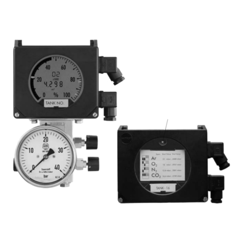
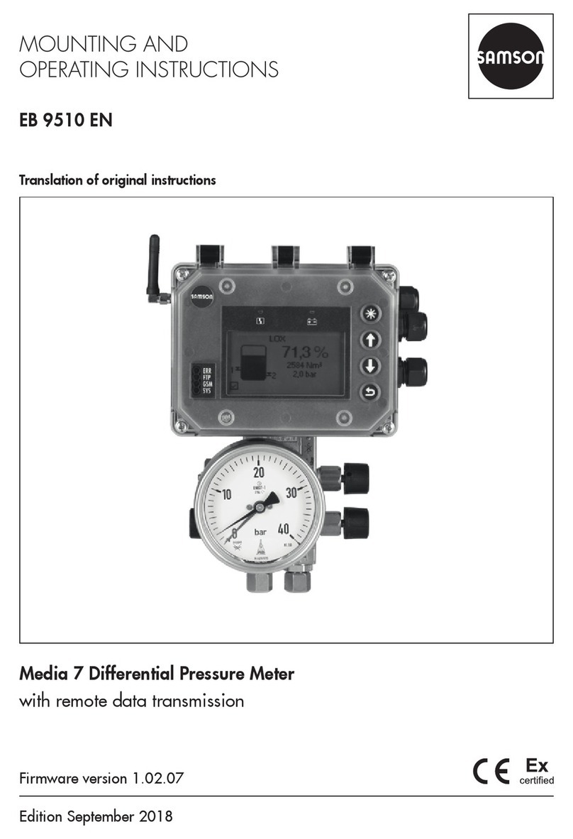
Samson Media 7 5007-1 Service manual

Translation of original instructions
EB 9510 EN
Firmware version 1.03.11
Edition January 2021
Media7 Differential Pressure Meter (Type5007-1)
with remote data transmission

Note on these mounting and operating instructions
These mounting and operating instructions assist you in mounting and operating the device
safely. The instructions are binding for handling SAMSON devices. The images shown in
these instructions are for illustration purposes only. The actual product may vary.
ÎFor the safe and proper use of these instructions, read them carefully and keep them for
later reference.
ÎIf you have any questions about these instructions, contact SAMSON‘s After-sales Service
(aftersalesservice@samsongroup.com).
Documents relating to the device, such as the mounting and operating
instructions, are available on our website at www.samsongroup.com >
Service & Support > Downloads > Documentation.
Denition of signal words
Hazardous situations which, if not avoided,
will result in death or serious injury
Hazardous situations which, if not avoided,
could result in death or serious injury
Property damage message or malfunction
Additional information
Recommended action
DANGER
!
WARNING
!
NOTICE
!
Note
Tip
EB 9510 EN

Contents
EB 9510 EN
1 Safety instructions and measures ................................................................1-1
1.1 Notes on possible severe personal injury ......................................................1-4
1.2 Notes on possible personal injury ................................................................1-6
1.3 Notes on possible property damage.............................................................1-7
2 Markings on the device ..............................................................................2-1
2.1 Nameplate .................................................................................................2-1
2.2 Label on devices for oxygen service..............................................................2-2
2.3 Firmware versions.......................................................................................2-3
2.4 Article code................................................................................................2-4
3 Design and principle of operation ...............................................................3-1
3.1 CongurationusingtheTROVIS-VIEWsoftware ............................................3-1
3.2 Versions .....................................................................................................3-4
3.2.1 Two-wire version.........................................................................................3-4
3.2.2 24Vversion...............................................................................................3-4
3.2.3 230Vversion.............................................................................................3-4
3.3 Device overview and operating controls........................................................3-4
3.4 Optional additional function ........................................................................3-6
3.4.1 Option modules..........................................................................................3-6
3.4.2 GSM module..............................................................................................3-6
3.4.3 Power supply unit with standby power supply (SPS) .......................................3-6
3.5 Technical data ............................................................................................3-8
3.6 Dimensions in mm.....................................................................................3-13
3.6.1 Dimensions for mounting (mm)...................................................................3-14
4 Shipment and on-site transport ...................................................................4-1
4.1 Accepting the delivered goods .....................................................................4-1
4.2 Removingthepackagingfromthedifferentialpressuremeterandmodules ......4-1
4.3 Transporting the differential pressure meter ...................................................4-1
4.4 Storing the differential pressure meter...........................................................4-1
5 Installation.................................................................................................5-1
5.1 Installation conditions..................................................................................5-1
5.2 Preparation for installation...........................................................................5-1
5.3 Setting up the optional additional functions...................................................5-2
5.3.1 Inserting option modules..............................................................................5-4
5.3.2 Inserting the GSM module ...........................................................................5-6
5.3.3 Setting up the standby power supply (SPS)....................................................5-8

Contents
EB 9510 EN
5.4 Mounting the differential pressure meter .....................................................5-10
5.5 Connecting the measuring lines..................................................................5-12
5.6 Establishing electrical connections ..............................................................5-12
6 Operation..................................................................................................6-1
6.1 Capacitive keys...........................................................................................6-1
6.2 Display ......................................................................................................6-2
6.2.1 Zoom function ............................................................................................6-2
6.3 Examples for the operation ..........................................................................6-3
7 Start-up and conguration..........................................................................7-1
7.1 Runningthestart-upwizard.........................................................................7-2
7.1.1 Optionmodulewizard ................................................................................7-3
7.2 Setting the user level....................................................................................7-4
7.3 Setting the local power line frequency...........................................................7-5
7.4 Calibrating the differential pressure..............................................................7-5
7.5 Calibrating the pressure sensor ....................................................................7-8
8 Operation..................................................................................................8-1
8.1 Differential pressure measurement ................................................................8-2
8.2 Liquid level measurement.............................................................................8-2
8.2.1 Density calculation in the tank – approximation method 0.1...........................8-3
8.3 Remotedatatransmission ............................................................................8-5
8.3.1 Status LEDs of the GSM module....................................................................8-5
8.3.2 Improving the signal quality.........................................................................8-6
9 Malfunctions ..............................................................................................9-1
9.1 Troubleshooting ..........................................................................................9-2
10 Servicing..................................................................................................10-1
10.1 Servicing explosion-protected devices.........................................................10-2
10.2 Periodic inspection and testing of the differential pressure meter ...................10-3
11 Decommissioning .....................................................................................11-1
12 Removal ..................................................................................................12-1
12.1 Removingtheoptionmodule......................................................................12-1
12.2 RemovingtheGSMmodule .......................................................................12-1
12.3 Removingthedifferentialpressuremeter .....................................................12-2
13 Repairs ....................................................................................................13-1
13.1 ReturningdevicestoSAMSON ..................................................................13-1

Contents
EB 9510 EN
14 Disposal...................................................................................................14-1
15 Certicates...............................................................................................15-1
16 Annex A (conguration instructions)..........................................................16-1
17 Annex B...................................................................................................17-1
17.1 Accessories ..............................................................................................17-1
17.1.1 Valveblock...............................................................................................17-1
17.1.2 Further accessories....................................................................................17-1
17.2 After-sales service.....................................................................................17-1

6 EB 9510 EN

EB 9510 EN 1-1
Safety instructions and measures
1 Safety instructions and measures
Intended use
TheMedia7DifferentialPressureMeterisamicroprocessor-controlledtransmitterwithdp
cell for measuring, indicating and transmitting the differential pressure, pressure or measured
variables derived from them. The device is suitable for cryogenic gases, liquids, gases and
vapors.Thedeviceisdesignedtooperateunderexactlydenedconditions(e.g.operating
pressure, process medium, temperature). Therefore, operators must ensure that the device is
onlyusedinoperatingconditionsthatmeetthespecicationsusedforsizingthedeviceatthe
ordering stage.
ThedifferentialpressuremetermustonlybeoperatedinhazardousareasinZone1orhigh-
er.Themeasurementofammableorexplosivemediaisonlypermittedwiththefollowing
approvals:
−Type5007-1-120x(ATEX):II1/2GExiaIIBT4Ga/Gb
−Type5007-1-121x(IECEx):ExiaIIBT4Ga/Gb(IECEx)
Incaseoperatorsintendtousethedeviceinotherapplicationsorconditionsthanspecied,
contact SAMSON.
SAMSON does not assume any liability for damage resulting from the failure to use the de-
vice for its intended purpose or for damage caused by external forces or any other external
factors.
ÎRefertothetechnicaldataforlimitsandeldsofapplicationaswellaspossibleuses.
Reasonably foreseeable misuse
The differential pressure meter is not suitable for the following applications:
−Useoutsidethelimitsdenedduringsizingandbythetechnicaldata
Furthermore, the following activities do not comply with the intended use:
−Use of non-original spare parts
−Performing maintenance activities not described in these instructions
Qualications of operating personnel
Thedevicemustbemounted,startedupandservicedbyfullytrainedandqualiedperson-
nel only; the accepted industry codes and practices are to be observed. According to these
mounting and operating instructions, trained personnel refers to individuals who are able to
judgetheworktheyareassignedtoandrecognizepossiblehazardsduetotheirspecialized
training, their knowledge and experience as well as their knowledge of the applicable stan-
dards.

1-2 EB 9510 EN
Safety instructions and measures
Explosion-protected versions of this device must be operated only by personnel who has un-
dergonespecialtrainingorinstructionsorwhoisauthorizedtoworkonexplosion-protected
devicesinhazardousareas.
Personal protective equipment
Werecommendwearingthefollowingprotectiveequipmentdependingontheprocessmedi-
um:
−Protective clothing, gloves, eye protection and respiratory protection in applications with
hot,coldand/orcorrosivemedia
ÎCheck with the plant operator for details on further protective equipment.
Revisions and other modications
Revisions,conversionsorothermodicationsoftheproductarenotauthorizedbySAMSON.
Theyareperformedattheuser'sownriskandmayleadtosafetyhazards,forexample.Fur-
thermore, the product may no longer meet the requirements for its intended use. Use of the
device is no longer permitted in this case.
Warning against residual hazards
To avoid personal injury or property damage, operators and operating personnel must pre-
venthazardsthatcouldbecausedinthedevicebytheprocessmediumandoperatingpres-
sure by taking appropriate precautions. Plant operators and operating personnel must ob-
serveallhazardstatements,warningandcautionnotesinthesemountingandoperatingin-
structions, especially for installation, start-up and service work.
Responsibilities of the operator
Operators are responsible for proper use and compliance with the safety regulations. Opera-
tors are obliged to provide these mounting and operating instructions to the operating per-
sonnel and to instruct them in proper operation. Furthermore, operators must ensure that op-
erating personnel or third parties are not exposed to any danger.
Responsibilities of operating personnel
Operating personnel must read and understand these mounting and operating instructions as
wellasthespeciedhazardstatements,warningandcautionnotes.Furthermore,theoperat-
ing personnel must be familiar with the applicable health, safety and accident prevention
regulations and comply with them.

EB 9510 EN 1-3
Safety instructions and measures
Referenced standards, directives and regulations
DeviceswithaCEmarkingfulllthefollowingrequirementsoftheDirectives:
−Type5007-1:2014/30/EU,2014/35/EU,2011/65/EU
−Type5007-1-1x0:2014/30/EU,2014/34/EU,2011/65/EU
−Type5007-1GSM:2014/53/EU,2011/65/EU
DeviceswithanEACmarkingfulllthefollowingrequirementsoftheRegulations:
−Type5007-1:TRCU020/2011
Seethe‘Certicates’sectionforthedeclarationsofconformityandEACcerticates.
Referenced documentation
The following documents apply in addition to these mounting and operating instructions:
−OperatingInstructions'Media7DifferentialPressureMeter–CongurationwithTROVIS-
VIEW'uEB9510-2
−Mounting and operating instructions for mounted pipeline valves (strainers, shut-off
valves etc.)
−For oxygen service: Manual uH01

1-4 EB 9510 EN
Safety instructions and measures
1.1 Notes on possible severe personal injury
DANGER
!
Risk of fatal injury due to electric shock (230V version).
ÎBeforeconnectingwiring,performinganyworkonthedeviceoropeningthedevice,
disconnect the voltage supply and protect it against unintentional reconnection.
ÎOnly use power interruption devices that are protected against unintentional recon-
nection of the power supply.
Risk of fatal injury due to the ignition of an explosive atmosphere.
Incorrect installation, operation or maintenance of the differential pressure meter in
potentially explosive atmospheres may lead to ignition of the atmosphere and ultimately
to death, even with a harmless supply voltage.
ÎFormountingandelectricalinstallationinhazardousareas,observetheexplosion
protection approvals as well as the relevant electrotechnical regulations and the
accidentpreventionregulationsthatapplyinthecountryofuse.EN60079-14
applies in Europe.
ÎDo not connect the electrical supply before mounting is completed and any unused
cable entries have been sealed.
ÎInstallation, operation or maintenance of the differential pressure meter must only be
performedbypersonnelwithqualicationsaccordingtoClause4.5ofIEC60079-
14whohasundergonespecialtrainingorinstructionsorwhoisauthorizedtowork
onexplosion-protecteddevicesinhazardousareas.
Risk of fatal injury as a result of electrostatic discharge at the housing.
The housing of the differential pressure meter is made of polycarbonate and may be-
come electrostatically charged when handled incorrectly. An electric spark generated by
electrostatic discharge may lead to ignition of a potentially explosive atmosphere and
cause death.
ÎEnsure that the device, cables and other plant components cannot rub against each
other.
ÎDo not rub dry the housing surface of the differential pressure meter.
ÎOnly use a damp cloth or wipes (e.g. with diluted mild soap or detergent) to clean
the housing surface.

EB 9510 EN 1-5
Safety instructions and measures
DANGER
!
Risk of bursting in pressure equipment.
The dp cell of the differential pressure meter and pipelines are pressure equipment
accordingtoDirective2014/68/EU.Improperopeningcanleadtoleakageorbursting
of plant or device components.
ÎBeforestartinganyworkonthedifferentialpressuremeter,depressurizeallplant
sections affected as well as the dp cell.
ÎDrain the process medium from all the plant sections affected as well as the dp cell.
ÎWearprotectiveclothingasspeciedinthematerialsafetydatasheet(MSDS)for
the process medium.
Risk of injury due to incorrect handling of oxygen or cryogenic gases in applications.
The differential pressure meter is frequently used for oxygen service or applications with
cryogenicgases(seethe'Markingsonthedevice'section).Oxygenisahazardous
substance, which reacts quickly, leading to combustion and explosions. Contact with
cryogenic gases causes severe frostbite and cold burns (cryogenic burns). Operating
personnelmustbetrainedfortheseapplications.Unqualiedoperatingpersonnel
expose themselves and others to an increased risk of injury.
ÎOperatingpersonnelmustbesufcientlytrainedandbemadeawareofthehazards
in applications involving oxygen or cryogenic gases.
ÎWhenreplacingpartsthatcomeintocontactwithgaseousoxygen,wearsuitable
gloves and do not contaminate any parts with oil or grease.
ÎInstructions and information on how to safely handle devices for oxygen service can
be found in the Manual uH01.

1-6 EB 9510 EN
Safety instructions and measures
1.2 Notes on possible personal injury
WARNING
!
Incorrect electrical connection will render the explosion protection unsafe.
ÎOnly operate the device with an intrinsically safe power supply while complying
with the maximum permissible values for Uior U0, lior I0and Pior P0.
ÎAdhere to the terminal assignment and correct polarity.
ÎDo not undo the enameled screws.
Risk of personal injury due to residual process medium inside the dp cell.
Whileworkingonthedpcell,residualprocessmediumcanescapeand,dependingon
its properties, may lead to personal injury, e.g. (chemical) burns.
ÎDrain the process medium from all the plant sections concerned and the dp cell, if
possible.
ÎWearprotectiveclothing,safetyglovesandeyeprotection.
Risk of personal injury due to process medium escaping from a damaged dp cell.
The long-term durability of all parts (including the dp cell) that come into contact with
the process medium must be ensured.
ÎOnly use process media which, according to their properties, are compatible with
the materials used in the device.
ÎObserve the material numbers listed in the technical data as well as the material
safety data sheets (MSDS) of the process media.
Risk of burn injuries due to hot or cold components and pipelines.
Depending on the process medium, valve components and pipelines may get very hot
or cold and cause burn injuries.
ÎAllow components and pipelines to cool down or warm up to the ambient tempera-
ture.
ÎWearprotectiveclothingandsafetygloves.

EB 9510 EN 1-7
Safety instructions and measures
1.3 Notes on possible property damage
NOTICE
!
Risk of dp cell damage due to unsuitable medium properties.
Thedeviceisdesignedforprocessmediawithdenedproperties.
ÎOnly use process media suitable for the device version according to the article code
(see the 'Markings on the device' section).
Risk of damage to the electronics due to the incorrect connection of the electrical
power supply.
Thedifferentialpressuremeterisdesignedtooperateunderexactlydenedelectrical
conditions.
ÎObserve the permissible tolerances of the supply voltage.
ÎFor wiring, you are required to observe the relevant regulations concerning device
safety and electromagnetic compatibility.
Risk of damage to the device due to incorrect mounting position.
ÎMount the device in the upright position only.
Risk of damage to components for optional additional functions due to incorrect
handling during installation.
Totailorthedifferentialpressuremetertoaparticulartask,itcanbettedwithoption
modules, a GSM module and a standby power supply. Special care needs to be taken
when inserting and removing these components.
ÎBeforeinsertingorremovingthecomponentsforoptionaladditionalfunctions,
disconnect the power supply.
ÎObservetheESDrequirementsaccordingtoIEC61340-5-1.
Risk of damage to the dp cell due to incorrect use of oxygen.
Whenliquidoxygenisusedastheprocessmedium,thepermissibletemperaturerange
is exceeded.
ÎWhenthedeviceisusedforoxygenservice,onlyallowthedpcellandany
SAMSON accessories (e.g. valve block) to come into contact with gaseous oxygen.
ÎDo not allow the oxygen pressure to exceed the maximum permissible limit of
50bar.

1-8 EB 9510 EN

EB 9510 EN 2-1
Markings on the device
2 Markings on the device
2.1 Nameplate
Made in Germany
Output ;Supply
Model 5007 -
Differential Pressure Meter
5007-1
pressure sensor
Firmware
Serial no.
Var.-ID
4
1 2
5
6
7
3
SAMSON AG, Germany
for ambient temperature IP 66, IP 67
See technical data
Made in Germany
Supply
Model 5007 -
Differential Pressure Meter
5007-1
pressure sensor
Firmware
Serial no.
Var.-ID
4
2
5
6
7
3
SAMSON AG, Germany
for ambient temperature IP 66, IP 67
See technical data
Made in Germany
Supply
Model 5007 -
Differential Pressure Meter
5007-1
pressure sensor
Firmware
Serial no.
Var.-ID
4
2
5
6
7
3
SAMSON AG, Germany
for ambient temperature IP 66, IP 67
See technical data
1 Signal range
2 Electric power supply
3Pressuresensor(yes/no)1)
4 Model number
5 Firmware version
6CongurationID
7 Serial number2)
8 Type of protection for explosion-protected devices
9Temperaturelimitsinthetestcerticatesforexplosion-
protected devices
10 Optional additional function
11 Ordering number
12 Pressure rating
13 Measuring range
14 International Mobile Equipment Identity3)
15 QRcode
16 Activation code
Two-wire version (without explosion protection):
24Vversion(withoutexplosionprotection):
230Vversion(withoutexplosionprotection):
1) No pressure sensor is used in devices for use with
ammablegases.Therefore,itisnotspeciedonthe
nameplate.
2) Thersttwoguresoftheserialnumberinreverse
order indicate the year of manufacture (example:
serial number 71xxxxx ÎYear of manufacture =
2017).
3) 15-digitserialnumberforuniqueidenticationof
mobile devices

2-2 EB 9510 EN
Markings on the device
Made in Germany
Output ;Supply
Model 5007 -
Differential Pressure Meter
5007-1
pressure sensor
Firmware
Serial no.
Var.-ID
4
1 2
5
6
7
3
SAMSON AG, Germany
*See EU Type Exam. Certificate for further values
0044
–20 °C ≤ Ta* ≤ +70 °C
8
9
IP 66, IP 67
Explosion-protected version (two-wire version only):
Var.-ID
Serial no.
Nominal range mbar
6
12
7
13
5007
dp cell:
IMEI:
5007 Option module [GSM]
Firmware
Model
Activation-Code:
4
15
16
14
5
GSM module:
5007-1
Module
10
8
1
11
Option module:
2.2 Label on devices for oxygen service
Differential pressure meters intended to measure gaseous oxygen are labeled as follows:
Cleaned and degreased for oxygen according to:
Inspection procedure according to appendix: A.2 and A.3
ISO 23208 - cleaned oxygen
These versions are cleaned and assembled under special conditions.

EB 9510 EN 2-3
Markings on the device
2.3 Firmware versions
Firmware revisions
Old New
1.00.05 1.01.07
• AOoptions(llinglevel,differentialpressure,pressuresensor):
test mode and fault alarm output
• Two-wire output: test mode and fault alarm output
• Batteryvoltagereading
• Optionmodulewizard
1.01.07 1.02.07
• OptionmodulewizardforAI,AIAandAOoptions
• New'Powerlinefrequency'parametertolteroutanydisturbances
• Italian, French and Spanish added as menu and display language
• Restrictedofinecongurationofoptions
• Default setting of write protection (data transmission module) changed (inactive)
• Zero and span calibration for the measured value of the analog input
1.02.07 1.03.09
• Zoomedviewofthedisplayreadingduringtanklling
• Automatic density correction for the medium
• Changes made to the tank and medium database
• Powersupplyunit(100to230VAC)added
• Increased measuring accuracy of the analog inputs
• Improved operation
• RussianandTurkishaddedasmenuanddisplaylanguage
1.03.09 1.03.11
Internal revisions

2-4 EB 9510 EN
Markings on the device
2.4 Article code
Media 7 5007-1- x x x x x x x x x 0xxxxxxxx
With4“LCD
Explosion protection
Without 000
ATEX: II2GExiaIIBT4Gb 110
IECEx: ExiaIIBT4Gb 111
ATEX: II1/2GExiaIIBT4Ga/Gb 120
IECEx: ExiaIIBT4Ga/Gb 121
Energy supply
Two-wire 0
Powersupplyunit,24to36VDC 1
Powersupplyunit,100to230VAC 2
Option module slot 1
Without 0
AO: Analog output 5
AI: Analog input 4
AIA: Analog input active 6
Option module slot 2
Without 0
AO: Analog output 5
AI: Analog input 4
AIA: Analog input active 6
Option module slot 3
Without 0
AO: Analog output 5
AI: Analog input 4
AIA: Analog input active 6
Option module slot 4
Without 0
AO: Analog output 5
AI: Analog input 4
AIA: Analog input active 6

EB 9510 EN 2-5
Markings on the device
Media 7 5007-1- x x x x x x x x x 0xxxxxxxx
GSM module with antenna
Without 0
GSM module with antenna (including SIM
card) 2
dp cell material
Brass 0
Measuring range
160mbar 0 2
600mbar 0 5
1600mbar 0 7
3600mbar 0 9
Diaphragm
ECO:–40to+80°C,REACHcompliant 0
Version
VersionforcryogenicgasesaccordingtoDINENISO23280,packedinplasticbags,
freeofoilandgreaseaccordingtocompanystandardWN1.34-2Sheets1and1.1
1 1
VersionforoxygenaccordingtoDINENISO25208,packedinplasticbags,
freeofoilandgreaseaccordingtocompanystandardWN1.34-2Sheets1and
1.1
1 2
Pressure rating
50bar,versionforoxygenservice,withoutvalveblock 1
60bar,withoutvalveblock 2
50bar,withvalveblockPN50 3
Pressure sensor
Without 1
With,non-ammablegases 2

2-6 EB 9510 EN
Table of contents
Other Samson Measuring Instrument manuals

Samson
Samson Media 7 Service manual

Samson
Samson D-150 User manual

Samson
Samson Media 6 User manual

Samson
Samson 2100 Series Troubleshooting guide

Samson
Samson 1100 SERIES User manual

Samson
Samson 024.85 User manual

Samson
Samson 2162 Operating manual

Samson
Samson 411 120 Operating manual

Samson
Samson Media 05 Service manual

Samson
Samson Media 6 Service manual
Popular Measuring Instrument manuals by other brands

MicroElektronika
MicroElektronika GSM click manual

Niigata seiki
Niigata seiki GDCS-150F user manual

Inficon
Inficon BPG400 instruction sheet

Bosch
Bosch DLE 40 Professional Original instructions

Endress+Hauser
Endress+Hauser Prosonic T FMU30 Brief operating instructions

National Instruments
National Instruments FD-11613 manual