EB 6116 EN 7
General safety instructions
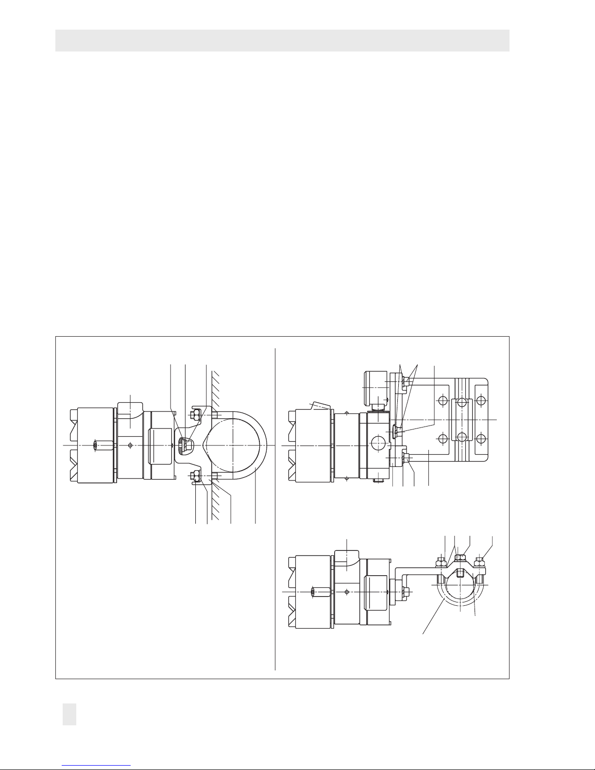
2.3 Principle of operation
See Fig.2 on page 6.
The device consists of an i/p converter mod-
ule and a downstream volume booster.
When operated, the supplied direct current i
ows through the plunger coil (2) located in
the eld of a permanent magnet (3). At the
balance beam (1), the force of the plunger
coil, which is in proportion to the current, is
balanced against the force of the dynamic
backpressure. The backpressure is produced
on the apper plate (6) by the air jet leaving
the nozzle (7).
The supply air (SUPPLY 8) ows to the bot-
tom chamber of the volume booster (8) and
a certain amount of air determined by the
diaphragm position ows past the sleeve (9)
and leaves through the output (OUTPUT 36).
As the input current and the forces acting on
the plunger coil increase, the apper (6)
moves closer to the nozzle (7). This causes
the backpressure and the cascade pressure
pK upstream of the restriction (8.2) to in-
crease until the cascade pressure corre-
sponds with the input current.
The increasing cascade pressure pushes the
diaphragm (10) and the plug sleeve (9)
downwards. As a result, the supply air caus-
es the output pressure pA to increase until a
new state of equilibrium is reached in the di-
aphragm chambers.
When the cascade pressure drops, the dia-
phragm moves upwards, releasing the plug
sleeve and thus allowing the output pressure
pA to escape through the venting (EXHAUST)
until the forces are equal again.
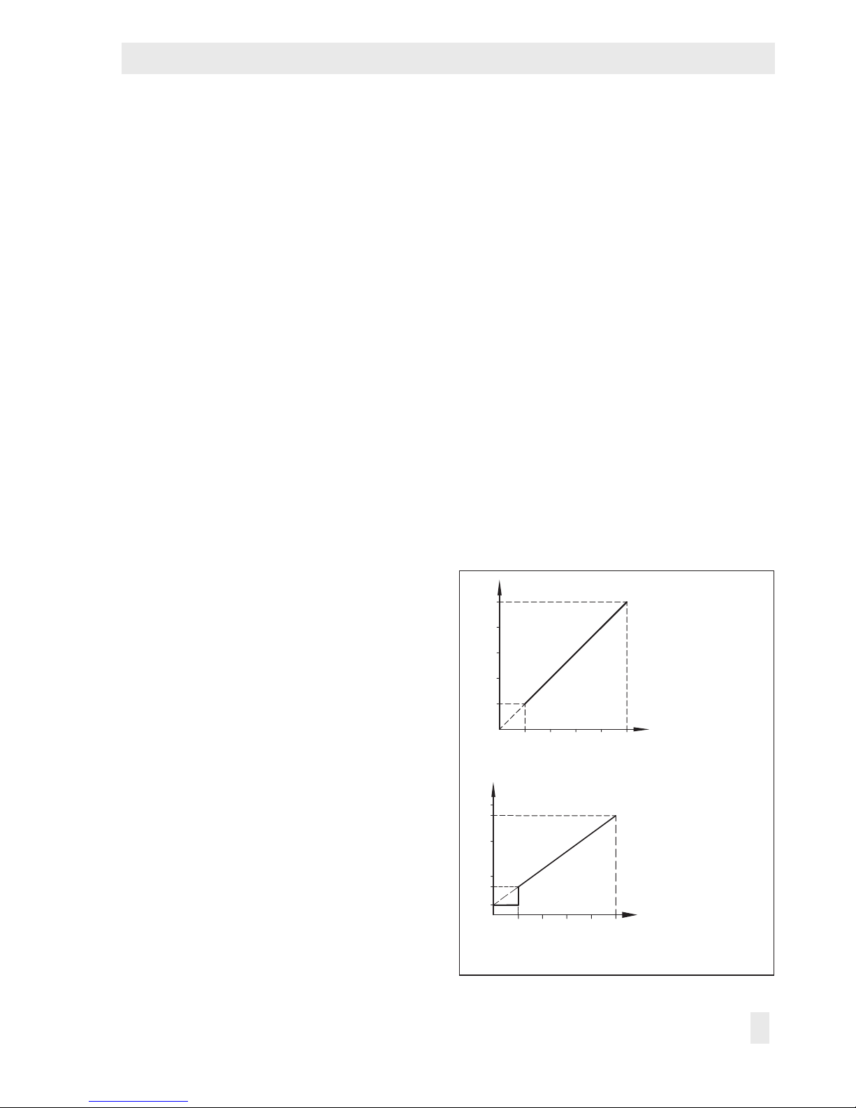
Switch-off electronics (see Fig.3)
Devices with an input range from 4 to
20mA have a slide switch which activates
the switch-off electronics. This function allows
the input signal to be set to 0mA when the
signal falls below the switching point of
4.08± tolerance. This causes the pneumatic
output to be vented to approximately
100mbar. This guarantees, for example, the
tight shut-off function of a valve.
This function requires a characteristic which
passes through the zero point, for example,
for the version with 4 to 20mA/0.2 to 1bar.
If the characteristic line does not pass
through zero, for example, for an allocated
output signal from 0.8 to 2.7bar, then the
pneumatic output is vented to a remaining
pressure of approx. 0.3bar when the
switch-off electronics are activated.
4812 16 20 m