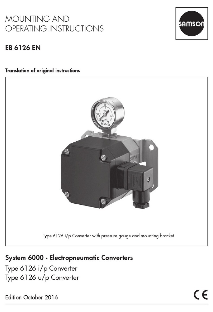
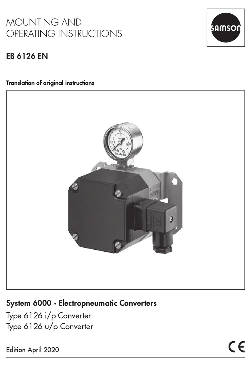
Samson 6134 Service manual

Translation of original instructions
EB 6134 EN
Edition May 2021
Type6134 p/i Converter
for two-wire connection
Type 6134-04 p/i Converter with one or two p/i
converter units, rail-mounting unit
Type 6134-x3 p/i Converter, eld unit

Note on these mounting and operating instructions
These mounting and operating instructions assist you in mounting and operating the device
safely. The instructions are binding for handling SAMSON devices. The images shown in
these instructions are for illustration purposes only. The actual product may vary.
ÎFor the safe and proper use of these instructions, read them carefully and keep them for
later reference.
ÎIf you have any questions about these instructions, contact SAMSON‘s After-sales Service
(aftersalesservice@samsongroup.com).
Documents relating to the device, such as the mounting and operating
instructions, are available on our website at www.samsongroup.com >
Service & Support > Downloads > Documentation.
Definition of signal words
Hazardous situations which, if not avoided,
will result in death or serious injury
Hazardous situations which, if not avoided,
could result in death or serious injury
Property damage message or malfunction
Additional information
Recommended action
DANGER
!
WARNING
!
NOTICE
!
Note
Tip
EB 6134 EN

Contents
EB 6134 EN
1 Safety instructions and measures ................................................................1-1
1.1 Notes on possible severe personal injury ......................................................1-4
1.2 Notes on possible personal injury ................................................................1-4
1.3 Notes on possible property damage.............................................................1-5
1.4 Special instructions concerning explosion protection ......................................1-6
2 Marking on the device................................................................................2-1
2.1 Nameplate .................................................................................................2-1
2.2 Article code................................................................................................2-2
3 Design and principle of operation ...............................................................3-1
3.1 Technical data ............................................................................................3-2
3.1.1 Dimensions in mm.......................................................................................3-4
4 Shipment and on-site transport ...................................................................4-1
4.1 Accepting the delivered goods .....................................................................4-1
4.2 Removing the packaging from the device ......................................................4-1
4.3 Transporting the device................................................................................4-1
4.4 Storing the device .......................................................................................4-1
5 Installation.................................................................................................5-1
5.1 Installation conditions..................................................................................5-1
5.2 Preparation for installation...........................................................................5-1
5.3 Mounting the converter................................................................................5-2
5.4 Electrical connection....................................................................................5-2
5.5 Pneumatic connection..................................................................................5-4
5.6 Accessories ................................................................................................5-6
6 Operation..................................................................................................6-1
7 Malfunction................................................................................................7-1
7.1 Troubleshooting ..........................................................................................7-1
7.2 Emergency action .......................................................................................7-2
8 Servicing....................................................................................................8-1
8.1 Tuning zero and span..................................................................................8-1
8.2 Periodic inspection and testing of the converter..............................................8-2
9 Removal ....................................................................................................9-1
10 Repairs ....................................................................................................10-1
10.1 Servicing explosion-protected devices.........................................................10-1
10.2 Returning devices to SAMSON ..................................................................10-1
11 Disposal...................................................................................................11-1

Contents
EB 6134 EN
12 Certicates...............................................................................................12-1
13 Annex......................................................................................................13-1
13.1 Accessories ..............................................................................................13-1
13.2 After-sales service.....................................................................................13-1

EB 6134 EN 1-1
Safety instructions and measures
1 Safety instructions and measures
Intended use
The Type6134 p/i Converter converts a pneumatic signal into a standardized electric signal.
It is especially used as an intermediate element between pneumatic and electric control and
measuring equipment.
The pneumatic input signal from 0.2 to 1bar is converted into an electric DC signal from 4
to 20mA.
The device is designed to operate under exactly dened conditions (e.g. input signal, pres-
sure). Therefore, operators must ensure that the device is only used in operating conditions
that meet the specications used for sizing the device at the ordering stage. In case operators
intend to use the device in other applications or conditions than specied, contact SAMSON.
SAMSON does not assume any liability for damage resulting from the failure to use the de-
vice for its intended purpose or for damage caused by external forces or any other external
factors.
ÎRefer to the technical data and nameplate for limits and elds of application as well as
possible uses.
Reasonably foreseeable misuse
The device is not suitable for the following applications:
−Use outside the limits dened by the technical data
Furthermore, the following activities do not comply with the intended use:
−Use of non-original spare parts
−Performing service and repair work not described
Qualications of operating personnel
The device must be mounted, started up, serviced and repaired by fully trained and qualied
personnel only; the accepted industry codes and practices must be observed. According to
these mounting and operating instructions, trained personnel refers to individuals who are
able to judge the work they are assigned to and recognize possible hazards due to their spe-
cialized training, their knowledge and experience as well as their knowledge of the applica-
ble standards.
Explosion-protected versions of this device must be operated only by personnel who has un-
dergone special training or instructions or who is authorized to work on explosion-protected
devices in hazardous areas.

1-2 EB 6134 EN
Safety instructions and measures
Personal protective equipment
No personal protective equipment is required for the direct handling of the device.
We recommend checking the hazards posed by the plant and the process medium being
used (e.g. uGESTIS (CLP) hazardous substances database).
ÎProtective clothing, gloves, eye protection and respiratory protection in applications with
hot, cold and/or corrosive media
ÎWear hearing protection when working near the valve
ÎHard hat
ÎSafety harness when working at height
ÎSafety footwear, ESD (electrostatic discharge) footwear, if necessary
ÎCheck with the plant operator for details on further protective equipment.
Revisions and other modications
Revisions, conversions or other modications of the product are not authorized by SAMSON.
They are performed at the user's own risk and may lead to safety hazards, for example. Fur-
thermore, the product may no longer meet the requirements for its intended use.
Warning against residual hazards
To avoid personal injury or property damage, operators and operating personnel must pre-
vent hazards by taking appropriate precautions. Plant operators and operating personnel
must observe all hazard statements, warning and caution notes in these mounting and oper-
ating instructions.
Responsibilities of the operator
Operators are responsible for proper use and compliance with the safety regulations. Opera-
tors are obliged to provide these mounting and operating instructions as well as the refer-
enced documents to the operating personnel and to instruct them in proper operation. Fur-
thermore, operators must ensure that operating personnel or third parties are not exposed to
any danger.
Responsibilities of operating personnel
Operating personnel must read and understand these mounting and operating instructions as
well as the referenced documents and observe the specied hazard statements, warnings
and caution notes. Furthermore, operating personnel must be familiar with the applicable
health, safety and accident prevention regulations and comply with them.

EB 6134 EN 1-3
Safety instructions and measures
Referenced standards, directives and regulations
Devices with a CE marking fulll the requirements of the Directives (see the 'Certicates' sec-
tion):
−Type6134-0: 2014/30/EU, 2011/65/EU
−Type6134-1: 2014/30/EU, 2014/34/EU, 2011/65/EU
−Type6134-2: 2014/30/EU, 2014/34/EU, 2011/65/EU
Devices with an EAC marking fulll the requirements of the Regulations (see the 'Certicates'
section):
−TR CU 004/2011
−TR CU 020/2011
Referenced documentation
The following documents apply in addition to these mounting and operating instructions:
−Mounting and operating instructions of the upstream pneumatic components
−Mounting and operating instructions of the downstream electric measuring and control
equipment
−The mounting and operating instructions of the components on which the converter is
mounted (valve, actuator, valve accessories etc.).

1-4 EB 6134 EN
Safety instructions and measures
1.1 Notes on possible severe personal injury
DANGER
!
Risk of fatal injury due to the ignition of an explosive atmosphere.
Incorrect installation, operation or maintenance of the device in potentially explosive at-
mospheres may lead to ignition of the atmosphere and ultimately to death.
ÎThe following regulations apply to installation in hazardous areas: EN60079-14
(VDE0165, Part1).
ÎInstallation, operation or maintenance of the device must only be performed by per-
sonnel who has undergone special training or instructions or who is authorized to
work on explosion-protected devices in hazardous areas.
Loss of Exd protection due to opening the enclosure cover or damage to the thread.
The protection against any explosions occurring inside the device is only effective with
ameproof gaps on the enclosure.
ÎKeep the enclosure cover rmly closed during operation.
ÎPut the device out of operation when its cover thread or connecting thread is dam-
aged. Replace it with a new device.
1.2 Notes on possible personal injury
WARNING
!
Risk of personal injury through incorrect operation, use or installation as a result of
information on the device being illegible.
Over time, markings, labels and nameplates on the device may become covered with
dirt or become illegible in some other way. As a result, hazards may go unnoticed and
the necessary instructions not followed. There is a risk of personal injury.
ÎKeep all relevant markings and inscriptions on the device in a constantly legible
state.
ÎContact our after-sales service to renew damaged, missing or incorrect nameplates
or labels.

EB 6134 EN 1-5
Safety instructions and measures
WARNING
!
Risk of personal injury due to exhaust air being vented.
While in operation, the device vents exhaust air over the vent plug.
ÎLocate the vent plug on the opposite side to the work position of operating person-
nel.
1.3 Notes on possible property damage
NOTICE
!
Risk of device damage due to failure to meet air quality requirements.
Insufcient air quality can damage components and seals inside the device.
ÎOnly use supply air that is dry and free of oil and dust.
ÎObserve the air quality according to ISO8573-1:2001.
ÎBlow through all air pipes and hoses thoroughly before connecting them.
Risk of device damage due to the maximum supply pressure being exceeded.
The maximum supply pressure for the device is restricted. A supply pressure higher
than the maximum permissible supply pressure may damage the device.
ÎRefer to the technical data for the maximum permissible supply pressure.
ÎMake sure that the air supply does not exceed the maximum permissible supply
pressure.

1-6 EB 6134 EN
Safety instructions and measures
1.4 Special instructions concerning explosion protection
Servicing explosion-protected devices
ÎObserve the following for servicing equipment in a section relevant for explosion
protection:
It must not be put back into operation until a qualied inspector has assessed the
equipment according to explosion protection requirements, has issued an inspec-
tion certicate or given the device a mark of conformity. Inspection by a qualied
inspector is not required if the manufacturer performed a routine test on the device
before putting it back into operation. Document the passing of the routine test by
attaching a mark of conformity to the device.
Replace explosion-protected components only with original, routine-tested compo-
nents by the manufacturer.
Devices that have already been used outside hazardous areas and are intended
for future use inside hazardous areas must comply with the safety requirements
placed on serviced devices. They must be subjected to testing according to the
specications in EN60079-19.
EN60079-19 applies to servicing explosion-protected devices.

EB 6134 EN 2-1
Marking on the device
2 Marking on the device
2.1 Nameplate
The nameplates shown were up to date at the time of publication of this document. The
nameplate on the device may differ from the one shown.
Version without explosion protection
SAMSON 6134
p/i
Converter
Model 6134 -
Var.-ID
Serial no.
Input
0utput
Supply
SAMSON AG D-60314 Frankfurt
Made in Germany
See technical data for ambient temperature
1
2
3
4
5
67
Explosion-protected version
SAMSON 6134
p/i
Converter
Model 6134 -
Var.-ID
Serial no.
SAMSON AG D-60314 Frankfurt
Input
0utput
Supply
Made in Germany
for permissible ambient temperature and maximum
* See technical data and explosion-protecion certificate
values for cennection to certified intrinsically safe circuits.
1
2
3
4
5
6
8
9
0044
Fig.2-1: Nameplate examples for Type6134 p/i Converter
Location of the nameplate
−Rail-mounting unit: the nameplate is located at the front of the device.
−Field unit: the nameplate is afxed with grooved pins to the side of the p/i converter.
1 Model number
2Conguration ID
3 Serial number
4 Input signal
5 Output signal
6 Supply voltage of the two-wire circuit
7 Data Matrix code
8 Type of protection
9Maximum permissible input values:
Ui(max. voltage), Ii(max. current), Pi(max.
power), Ci (inner capacitance) and Li(inner
inductance)

2-2 EB 6134 EN
Marking on the device
2.2 Article code
Type6134- x x x x x x x x x x
Explosion protection
Without 0
ATEX: II 2G EEx ia IIC T6 1 3
ATEX: II 2G EEx d IIC T6 2 3
Version
Field unit 3 0
Rail-mounting unit
With one p/i converter unit 0 4 1
With two p/i converter units 0 4 2
Input
0.2 to 1bar 1
3 to 15psi 2
Electrical connection
Rail-mounting unit, screw terminals 0 4 0
Field unit, ½-14NPT 3 0 1
Field unit, M20x1.5 3 0 2
Pneumatic connection
Hose connection 0 4 0 0
¼-18NPT 3 0 1
ISO-228/1 - G¼ 3 0 2
Degree of protection
IP20 04 000
IP54 3 0 1
IP65 3 0 2
Pressure gauge
Without 0
With 3 0 1
Temperature range
Tmin ≥ –20°C 0
Tmin ≥ –40°C 3 0 1
Output signal
4 to 20mA 0

EB 6134 EN 3-1
Design and principle of operation
0,2...1 bar
(3...15 psi)
1
2
p
P
3
4...20 mA
mA
12...30V DC
p Pneumatic input signal
1 Capacitive pressure sensor
2 Constant voltage source
3Measuring amplier and
potentiometers for adjusting
the measuring span (SPAN)
and ZERO
Fig.3-2: Schematic diagram of the Type6134 p/i Converter for two-wire connection
3 Design and principle of oper-
ation
The Type6134 p/i Converter converts a
pneumatic signal into a standardized electric
signal. It is especially used as an intermedi-
ate element between pneumatic and electric
control and measuring equipment.
The pneumatic input signal from 0.2 to 1bar
is converted into an electric DC signal from
4 to 20mA.
Principle of operation (see Fig.3-2)
A capacitive ceramic pressure sensor (1) is
used to convert the pressure p of the pneu-
matic input signal into an electric DC volt-
age signal. The DC voltage signal which is
proportional to the pressure is amplied to a
dened level in the measuring amplier (3).
The lower range value and span can be ad-
justed using potentiometers on the front pan-
el. The constant DC voltage source (2) is
used to supply the DC voltage at a constant
level. Control equipment can be connected to
the output circuit.
Output circuit
In two-wire systems, the maximum permissi-
ble load impedance at the output is:
UB= US– UARB= UB/20mA
UBMaximum permissible load impedance
RBMaximum permissible load
USSupply voltage of the two-wire circuit
UA12V, input voltage requirement (mini-
mum connected voltage required)
Example: US = 20VDC
Maximum permissible load impedance at the
output: UB=20V –12V=8V
Load: RB= UB/20mA = 400Ω

3-2 EB 6134 EN
Design and principle of operation
3.1 Technical data
Type Type6134-04 Types6134-03, -13, -23
Version Rail-mounting unit Field unit
Explosion protection according to ATEX – II 2G EEx ia IIC T6
II 2G EEx d IIC T6
p/i converter unit/device 1 or 2 1
Input 0.2 to 1bar (3 to 15psi), overloadable up to 5bar
(72.5psi)
Output 4 to 20mA1),2)
Perm. load at 0/4 to 20mA RB= US – 12V
20mA , US= supply voltage
Supply voltage Two-wire network
Voltage range 12 to 30VDC1)2)
Characteristic
Characteristic Output linear to input
Hysteresis Negligible
Deviation from terminal-based
linearity Terminal-based conformity: ≤ 0.2%3)
Ripple of output signal ≤ 0.5%3)
Effect of temperature ≤ 0.15%/10K for zero and span
EMC noise emission EN61000-6-3
EMC noise immunity EN61000-6-2
Ambient conditions, degree of protection, weight
Permissible ambient temperature –20 to +70°C Without explosion protection:
–20 to 70°C
–40 to 70°C (only with IP65)
With explosion protection2):
–20 to 60°C
–40 to 60°C (only with IP65)
Perm. storage temperature –40 to +80°C –40 to +80°C
Perm. transportation temperature –40 to +80°C –40 to +80°C
Degree of protection acc. to EN60529 IP20 IP54/IP65

EB 6134 EN 3-3
Design and principle of operation
Type Type6134-04 Types6134-03, -13, -23
Version Rail-mounting unit Field unit
Weights
1 converter unit 0.225kg 1.005kg
2 converter units 0.285kg –
Installation and connections
Mounting orientation Any Vent plug facing downward
Air connection Hose connection for
4x1mm, 6mm outside
diameter
2x tapped holes (use of left or
right hole optional):
ISO228/1-G¼ or ¼-18NPT
Electrical connection
Female thread – M20x1.5 or ½-14NPT
Terminals for wires 0.5 to 2.5mm² 0.5 to 2.5mm² (internal)
Fixed wires 0.2 to 4mm² 0.2 to 4mm²
Flexible wires 0.2 to 2.5mm² 0.2 to 2.5mm²
Mounting
35mm top-hat rail,
DINEN60715
Bracket for wall mounting
(included in scope of delivery) or
pipe mounting for 2” pipes
(order no. 1400-5656)
1) Type6134-13: intrinsically safe circuit
2) See 'Certicates' section for details (electric data, connection conditions, etc.)
3) All errors specied based on output span

3-4 EB 6134 EN
Design and principle of operation
3.1.1 Dimensions in mm
50.5
88
70
46.5
70
88
Ø8
Ø60
46.541
~64.5
12.5
115.5
2*
2* 2*
6
21
44 84
1
3
2
110
80
45˚
120
100
116
166
69.5
50
Ø30
Ø7
10
7
563
Rail-mounting unit
Field unit
−Pipe mounting for 2” pipes (below)
−Wall mounting (right)
1 Top-hat rail
2 Pneumatic connection (input)
2* Pneumatic connection (input)
optional use of left or right
3 Electrical connection (output)
4 Pipe mounting (order no. 1400-5656)
5 Wall mounting material included in
scope of delivery (order no. 1400-8837)
6Vent plug IP54/IP65
7 Pressure gauge (order no. 1400-8838)

EB 6134 EN 4-1
Shipment and on-site transport
4 Shipment and on-site trans-
port
The work described in this section is only to
be performed by personnel appropriately
qualied to carry out such tasks.
4.1 Accepting the delivered
goods
After receiving the shipment, proceed as fol-
lows:
1. Check the scope of delivery. Check that
the specications on the nameplate of the
device match the specications in the de-
livery note. See the 'Markings on the de-
vice' section for nameplate details.
2. Check the shipment for transportation
damage. Report any damage to
SAMSON and the forwarding agent
(refer to delivery note).
4.2 Removing the packaging
from the device
Observe the following sequence:
ÎDo not remove the packaging until im-
mediately before installation.
ÎDispose and recycle the packaging in ac-
cordance with the local regulations.
4.3 Transporting the device
ÎPack the device properly to comply with
terms of transportation.
Transport instructions
−Protect the device against external inu-
ences (e.g. impact).
−Protect the device against moisture and
dirt.
−Observe transport temperature (see the
'Design and principle of operation' sec-
tion).
4.4 Storing the device
Risk of device damage due to improper
storage.
ÎObserve the storage instructions.
ÎAvoid long storage times.
ÎContact SAMSON in case of different
storage conditions.
We recommend regularly checking the pre-
vailing storage conditions during long stor-
age periods.
NOTICE
!
Note
!

4-2 EB 6134 EN
Shipment and on-site transport
Storage instructions
−Protect the device against external inu-
ences (e.g. impact, shocks, vibration).
−Do not damage the corrosion protection
(coating).
−Protect the device against moisture and
dirt. In damp spaces, prevent condensa-
tion. If necessary, use a drying agent or
heating.
−Observe storage temperature (see the
'Design and principle of operation' sec-
tion).
−Do not place any objects on the device.

EB 6134 EN 5-1
Installation
5 Installation
The work described in this section is only to
be performed by personnel appropriately
qualied to carry out such tasks.
Risk of fatal injury due to the ignition of an
explosive atmosphere.
ÎObserve EN60079-14 (VDE0165,
Part1) for work on the converter in po-
tentially explosive atmospheres.
ÎWork in potentially explosive atmo-
spheres must only be performed by per-
sonnel who has undergone special train-
ing or instructions or who is authorized
to work on explosion-protected devices
in hazardous areas.
Loss of Exd protection due to opening the
enclosure cover or damage to the thread.
ÎKeep the enclosure cover rmly closed
during operation.
ÎPut the device out of operation when its
cover thread or connecting thread is
damaged. Replace it with a new device.
5.1 Installation conditions
Work position
The work position is the front view onto the
operating controls on the device seen from
the position of operating personnel.
Operators must ensure that, after installation
of the device, the operating personnel can
perform all necessary work safely and easily
access the device from the work position.
Vent plug
ÎLocate the vent plug on the opposite side
to the work position of operating person-
nel.
Mounting orientation
−Rail-mounting unit
The valve can be mounted in any desired
position.
−Field unit
–Install the converter horizontally with
the pressure gauge (or screw plug)
facing upward.
–Install the converter with degree of
protection IP54 in such a way that
the connection for the vent plug is al-
ways installed facing downward to
the oor.
5.2 Preparation for installation
Before installation, make sure the following
conditions are met:
−The converter is not damaged.
−The connections of the converter are
clean.
Proceed as follows:
ÎLay out the necessary material and tools
to have them ready during installation
work.
DANGER
!
DANGER
!

5-2 EB 6134 EN
Installation
ÎCheck any mounted pressure gauges to
make sure they function properly.
5.3 Mounting the converter
a) Rail-mounting unit
The converter is mounted on a top-hat rail
(DINEN60715).
ÎSnap the converter onto the top-hat rail.
b) Field unit
The converter is mounted to a wall or a pipe
(Ø2“) (see Fig.5-1).
Wall mounting
The converter is delivered with a wall mount-
ing bracket (see section5.6 for order num-
ber).
ÎFasten the mounting bracket to the back
of the converter using two screws.
ÎFasten the mounting bracket to the wall
using four screws.
Pipe mounting (Ø2“)
Required accessories: see section5.6
ÎUnfasten the clamp from the mounting
bracket.
ÎFasten the mounting bracket to the back
of the converter using two screws.
ÎPlace the clamp around the pipe. Hold it
in position and fasten it to the mounting
bracket.
765
8913 12
67
4
10
8911
5632
5 M6x25 screw
6 Spring washer B6
7 A6.4 washer
8 M8 nut
9A8.4 washer
12 Clamp for attachment to 2”
pipes
13 Wall or pipe bracket
Fig.5-1: Wall and pipe mounting (eld unit)
5.4 Electrical connection
For electrical installation, observe the rele-
vant electrotechnical regulations and the ac-
cident prevention regulations that apply in
the country of use. In Germany, these are
the VDE regulations and the accident pre-
vention regulations of the employers’ liability
insurance.
Table of contents
Other Samson Media Converter manuals

Samson
Samson 6132 Service manual

Samson
Samson 6000 Series Service manual

Samson
Samson 611 Service manual

Samson
Samson 6000 Series Service manual

Samson
Samson S-convert User manual

Samson
Samson 6000 Series Service manual

Samson
Samson DA40 User manual

Samson
Samson DS70 User manual

Samson
Samson 6111 Service manual

Samson
Samson 6111 Service manual