manuals.online logo
Brands
  1. Home
  2. •
  3. Brands
  4. •
  5. Samson
  6. •
  7. Valve Positioner
  8. •
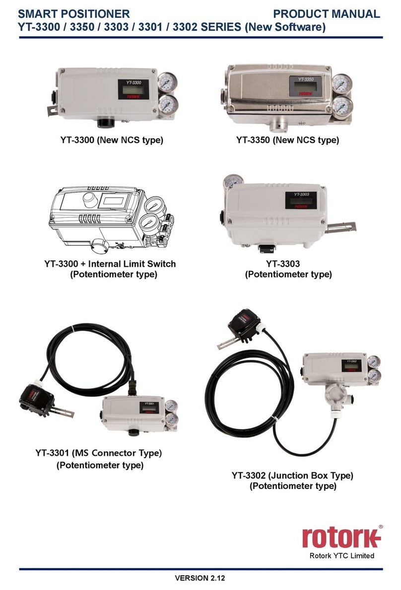
  9. Samson TROVIS 3730-1 User manual

Samson TROVIS 3730-1 User manual

Other manuals for TROVIS 3730-1

6

Other Samson Valve Positioner manuals

Samson 3730 Series Service manual

Samson

Samson 3730 Series Service manual

Samson 4763 Service manual

Samson

Samson 4763 Service manual

Samson 3730-4 User manual

Samson

Samson 3730-4 User manual

Samson 4785 Service manual

Samson

Samson 4785 Service manual

Samson 3730-2 Service manual

Samson

Samson 3730-2 Service manual

Samson 3730-4 User manual

Samson

Samson 3730-4 User manual

Samson 4763 Service manual

Samson

Samson 4763 Service manual

Samson TROVIS SAFE 3730 Series User manual

Samson

Samson TROVIS SAFE 3730 Series User manual

Samson TROVIS 3730-3 Service manual

Samson

Samson TROVIS 3730-3 Service manual

Samson 3767 Service manual

Samson

Samson 3767 Service manual

Samson 3730 Series Service manual

Samson

Samson 3730 Series Service manual

Samson 3730-0 Service manual

Samson

Samson 3730-0 Service manual

Samson 3785 series Service manual

Samson

Samson 3785 series Service manual

Samson TROVIS 3730-3 Service manual

Samson

Samson TROVIS 3730-3 Service manual

Samson 3730 Series Service manual

Samson

Samson 3730 Series Service manual

Samson 3248-1 Service manual

Samson

Samson 3248-1 Service manual

Samson 3730 Series Service manual

Samson

Samson 3730 Series Service manual

Samson FOUNDATION 3730-5 Instruction sheet

Samson

Samson FOUNDATION 3730-5 Instruction sheet

Samson TROVIS 3730-3 User manual

Samson

Samson TROVIS 3730-3 User manual

Samson 3730-2 User manual

Samson

Samson 3730-2 User manual

Samson 3730-4 Service manual

Samson

Samson 3730-4 Service manual

Samson 3767 Setup guide

Samson

Samson 3767 Setup guide

Samson TROVIS 3793 User manual

Samson

Samson TROVIS 3793 User manual

Samson 3730-6 Instruction sheet

Samson

Samson 3730-6 Instruction sheet

Popular Valve Positioner manuals by other brands

HALDER 23111.0016 Short instruction manual

HALDER

HALDER 23111.0016 Short instruction manual

Parker 404XE Series product manual

Parker

Parker 404XE Series product manual

Ytc TMP-3000 product manual

Ytc

Ytc TMP-3000 product manual

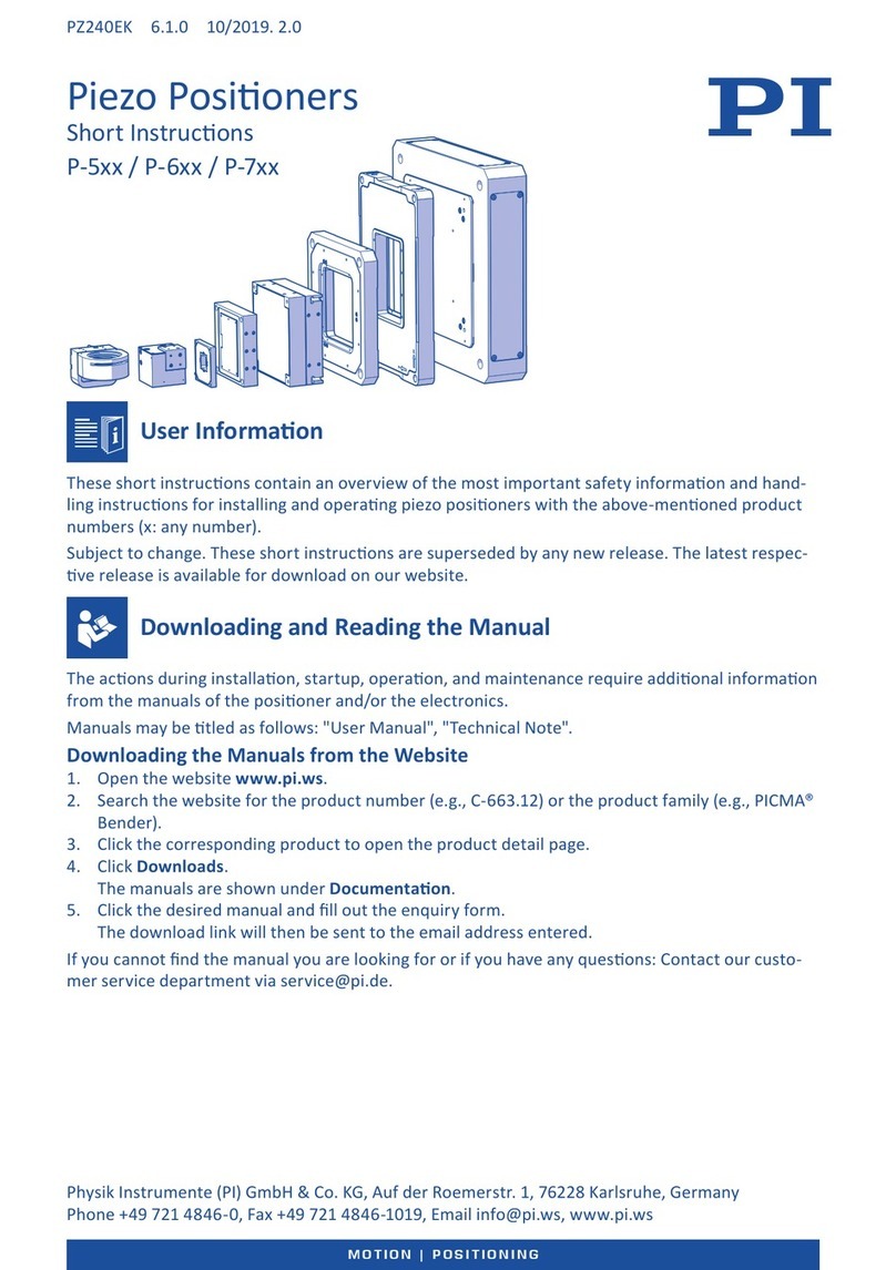
PI M-605 Series user manual

PI

PI M-605 Series user manual

Pepperl+Fuchs PXV100AS-F200-SSI-V19 manual

Pepperl+Fuchs

Pepperl+Fuchs PXV100AS-F200-SSI-V19 manual

RTK RE 3442 Series Installation and operating instructions

RTK

RTK RE 3442 Series Installation and operating instructions

CVS Controls 1200 instruction manual

CVS Controls

CVS Controls 1200 instruction manual

Westlock Quantum 2800 Installation & operating instructions

Westlock

Westlock Quantum 2800 Installation & operating instructions

ESCO Technologies ETS LINDGREN 2302-001 user manual

ESCO Technologies

ESCO Technologies ETS LINDGREN 2302-001 user manual

Parker MX80L series product manual

Parker

Parker MX80L series product manual

SMC Networks IP8000 manual

SMC Networks

SMC Networks IP8000 manual

Siemens SIPART PS2 operating instructions

Siemens

Siemens SIPART PS2 operating instructions

Burkert 8694 operating instructions

Burkert

Burkert 8694 operating instructions

iXBlue POSIDONIA II Technical description

iXBlue

iXBlue POSIDONIA II Technical description

Flowserve Logix 3200IQ Replacement instructions

Flowserve

Flowserve Logix 3200IQ Replacement instructions

Lang LHT500 Assembly instruction

Lang

Lang LHT500 Assembly instruction

Spirax Sarco SP7-21 quick start guide

Spirax Sarco

Spirax Sarco SP7-21 quick start guide

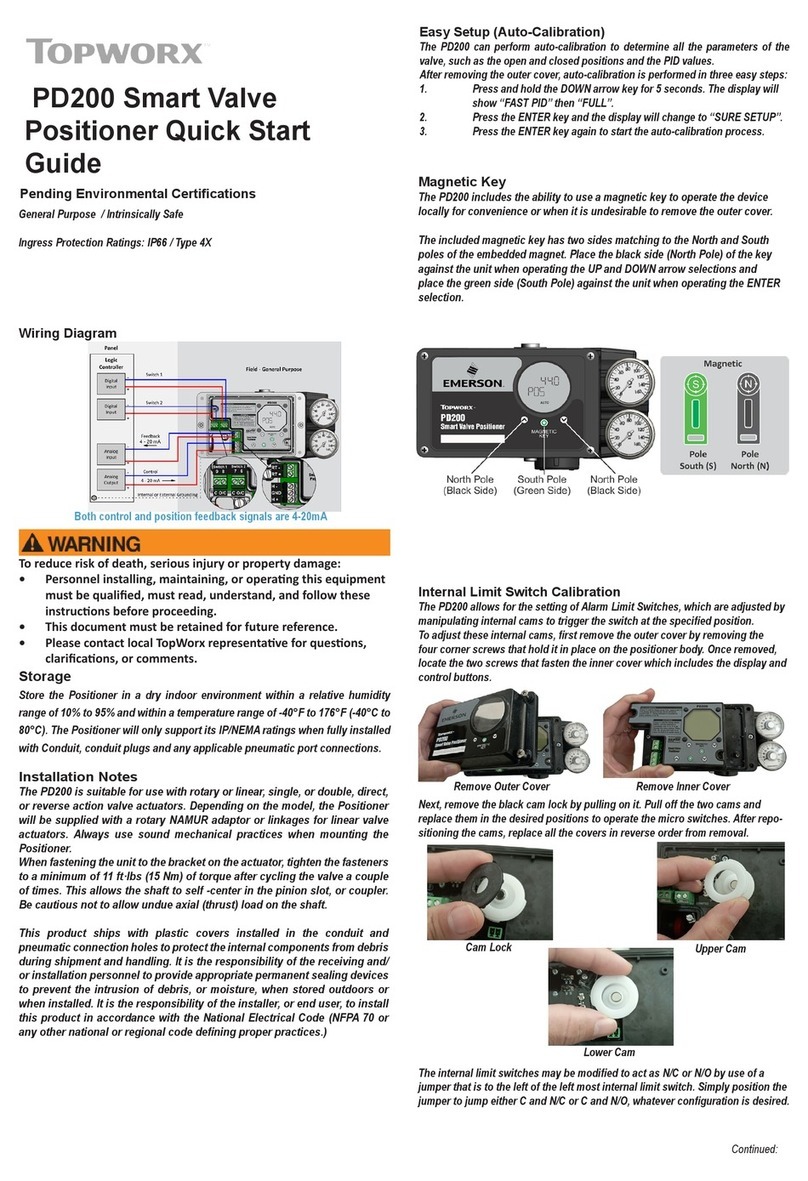
Topworx PD200 quick start guide

Topworx

Topworx PD200 quick start guide

manuals.online logo
manuals.online logoBrands
  • About & Mission
  • Contact us
  • Privacy Policy
  • Terms and Conditions

Copyright 2025 Manuals.Online. All Rights Reserved.

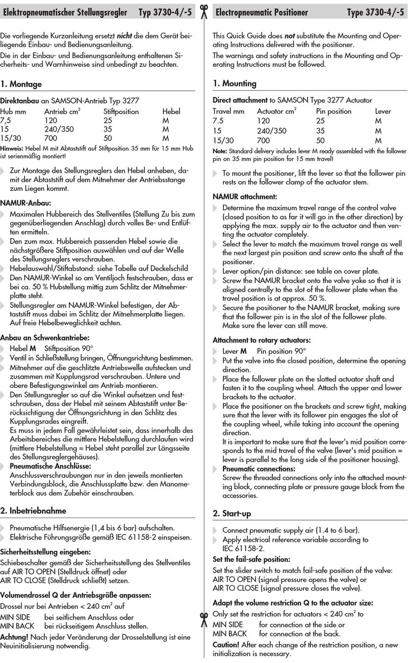
TROVIS3730-1 Electropneumatic Positioner
This quick guide does not replace the mounting and operating inst-
ructions supplied with the positioner. Observe the safety instructions
as well as the warning and caution notes specied in the mounting
and operating instructions.
1 Mounting
Direct attachment to SAMSON Type3277 Actuator
Travel [mm] Actuator [cm²] Lever Pin position
15 120, 175, 240, 350 M35
30 355, 700, 750 M50
ÎTo mount the positioner, lift the lever so that the follower pin rests
on the follower clamp of the actuator stem. Make sure the lever
can move freely.
NAMUR attachment
Travel [mm] Actuator [cm²] Travel Pin position
7.5 and 15 120, 175, 240, 350, 700, 750 M35
30 355, 700, 750 M50
30 1000, 1400, 2800 L70
60 1000, 1400, 2800 L100
120 1400, 2800 XL 200
250 1400 XXL 300
ÎDetermine the travel range of the control valve (closed position to
as far it will go in the other direction) by applying the max. supply
air to the actuator and then venting the actuator completely.
ÎFasten the lever with follower pin onto the shaft of the positioner.
Î
Fasten the NAMUR bracket onto the valve yoke so that it is aligned
centrally to the slot of the follower plate when the travel position
is at approx. 50%.
Î
Fasten the positioner to the NAMUR bracket, making sure that the
follower pin is in the slot of the follower plate. Make sure the lever
can move freely.
Attachment to rotary actuators
Lever Pin position
M90°
ÎPlace the valve to the closed position.
ÎPlace the follower plate on the slotted actuator shaft and fasten it
to the coupling wheel. Mount the top and bottom brackets to the
actuator.
ÎFasten the positioner on the bracket. Make sure that:
–
The lever with its follower pin engages into the slot of the coupling
wheel, while taking into account the opening direction.
– The lever in the mid valve position is parallel to the long side
of the positioner housing.
2 Preparation for start-up
1. Apply supply air (1.4 to 7bar).
2. Connect input signal (4 to 20mA).
i/p-Stellungsregler TROVIS3730-1
Die vorliegende Kurzanleitung ersetzt nicht die dem Gerät beiliegen
-
de Einbau- und Bedienungsanleitung. Die in der Einbau- und Bedie-
nungsanleitung enthaltenen Sicherheits- und Warnhinweise sind zu
beachten.
1 Montage
Direktanbau an SAMSON-Antrieb Typ3277
Hub [mm] Antrieb [cm²] Hebel Stiftposition
15 120, 175, 240, 350 M35
30 355, 700, 750 M50
ÎZur Montage des Stellungsreglers den Hebel anheben, damit der
Abtaststift auf dem Mitnehmer der Antriebsstange zum Liegen
kommt. Auf freie Hebelbeweglichkeit achten.
NAMUR-Anbau
Hub [mm] Antrieb [cm²] Hebel Stiftposition
7,5 und 15 120, 175, 240, 350, 700, 750 M35
30 355, 700, 750 M50
30 1000, 1400, 2800 L70
60 1000, 1400, 2800 L100
120 1400, 2800 XL 200
250 1400 XXL 300
Î
Hubbereich des Stellventils (Stellung ZU bis zum gegenüberlie-
genden Anschlag) durch volles Be- und Entlüften ermitteln.
ÎEntsprechenden Hebel mit Abtaststift auf der Welle des Stellungs-
reglers verschrauben.
ÎNAMUR-Winkel so am Ventiljoch festschrauben, dass er bei ca.
50% Hubstellung mittig zum Schlitz der Mitnehmerplatte steht.
Î
Stellungsregler am NAMUR-Winkel befestigen. Der Abtaststift
muss im Schlitz der Mitnehmerplatte liegen. Auf freie Hebelbe-
weglichkeit achten.
Anbau an Schwenkantriebe
Hebel Stiftposition
M90°
ÎVentil in ZU-Stellung bringen.
ÎMitnehmer auf die geschlitzte Antriebswelle aufstecken und zu-
sammen mit Kupplungsrad verschrauben. Untere und obere Be-
festigungswinkel am Antrieb montieren.
ÎStellungsregler am Winkel festschrauben. Darauf achten, dass
–
der Hebel mit seinem Abtaststift unter Berücksichtigung der
Öffnungsrichtung in den Schlitz des Kupplungsrads eingreift.
– der Hebel in der mittleren Hubstellung parallel zur Längsseite
des Stellungsreglergehäuses steht.
2 Inbetriebnahme vorbereiten
1. Pneumatische Hilfsenergie (1,4 bis 7bar) aufschalten.
2. Eingangssignal (4 bis 20mA) anschließen.
!
българскиезик[BG] · Čeština[CS] · Dansk[DA] · Deutsch[DE] · ελληνικά[EL]
English[EN] · Español[ES] · Eesti[ET] · Suomi[FI] · Français[FR]
Hrvatskijezik[HR] · Magyar[HU] · Italiano[IT] · 日本語 [JA]
Lietuviųkalba[LT] · Nederlands[NL] · Polski[PL] · Português[PT]
Română [RO] · Русский[RU] · Slovenčina[SK] · Slovenščina[SL] ·
Svenska[SV] · Türkçe[TR] · 中文[ZH]
Îwww.samsongroup.com
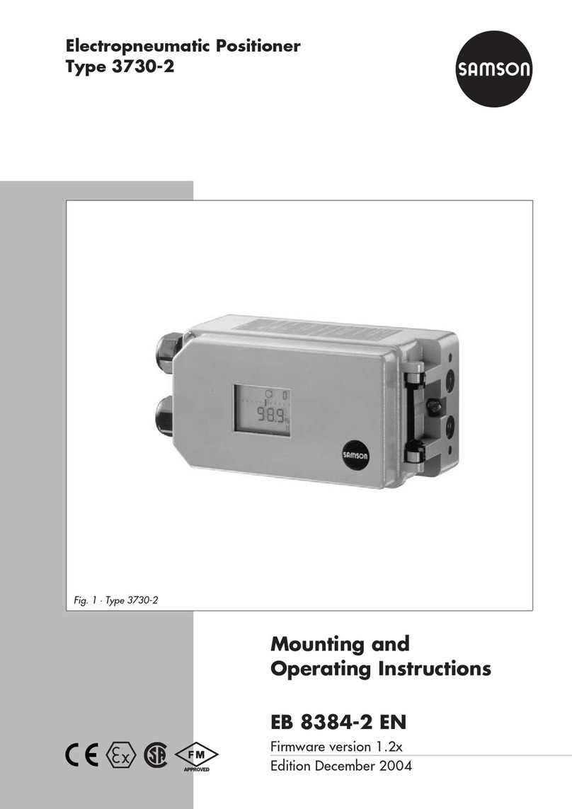
Edition August 2018 Quick Guide KA 8484-1 EN
Refer to associated mounting and operating instructions for details:
uEB8484-1 for TROVIS3730-1
3 Operation
Turn () the rotary pushbutton to select parameter codes and
values. Press ( ) to conrm setting. To change parameters, enable
conguration rst:
Code Meaning
P0 Status reading
P1 Reading direction
P2 Enable conguration
P3 Fail-safe position
P4 Pin position
P5 Nominal range
P6 Characteristic
P7 Set point
P8 Direction of action
P9 Gain KP
P10 Control response
P11 Pressure limitation
P12 Set point cutoff decrease
(end position w <)
P13 Set point cutoff increase (end
position w >)
P14 Switching mode of software
limit switch
P15 Switching threshold of soft-
ware limit switch 1
P16 Switching threshold of soft-
ware limit switch 2
Code Meaning
P17 Software limit switch test
P18 Position transmitter
P19 Fault indication function
P20 Position transmitter test
P21 Reading of set point w
P22 Start initialization
P23 Start zero calibration
P24 Manual mode
P25 Reset
P26 Restart
P27 Firmware version
E0 to E15 Errors (see EB)
Icon Meaning
Closed-loop operation
Manual mode
S
Fail-safe position
Conguration changed
Operation locked
Fault indication icon
1.  until Code P2 appears.
2.  to conrm. P2 blinks.
3. until OPEN appears.
4. to deactivate the locking.
4 Determining the fail-safe position
1.  until Code P3 appears.
2.  to conrm. P3 blinks.
3. and select ATO or ATC.
4.  to conrm the fail-safe position.
5 Initialization
WARNING! Risk of crushing! During initialization, the valve moves
through its entire travel range/angle of rotation.
Note: Before initialization, mount the positioner, apply the supply air
and connect the input signal.
For normal operation, simply start initialization (Code P22) after
checking the fail-safe position (Code P3). The positioner only works
with its default settings.
Note: Reset positioner to its default settings (Code P25) before chan-
ging its mounting position.
6 Codes/icons and their meaning
Ausgabe August 2018 Kurzanleitung KA 8484-1
3 Bedienung
Durch Drehen () des Dreh-/Druckknopfes werden Parameter-
codes und Werte ausgewählt. Drücken () des Knopfes bestätigt die
Auswahl. Um Parameter zu ändern, vorher die Kongurationsfrei-
gabe aktivieren:
Einzelheiten vgl. zugehörige Einbau- und Bedienungsanleitung:
uEB8484-1 für TROVIS3730-1
Code Bedeutung
P0 Betriebsanzeige
P1 Leserichtung
P2 Kongurationsfreigabe
P3 Sicherheitsstellung
P4 Stiftposition
P5 Nennbereich
P6 Kennlinie
P7 Sollwert
P8 Bewegungsrichtung
P9 Verstärkung KP
P10 Regelverhalten
P11 Druckbegrenzung
P12 Untere Dichtschließfunktion
(Endlage w <)
P13 Obere Dichtschließfunktion
(Endlage w >)
P14 Software-Grenzkontakt
Schaltmodus
P15 Grenzkontakt1 Schalt-
schwelle
P16 Grenzkontakt2 Schalt-
schwelle
Code Bedeutung
P17 Software-Grenzkontakt Test
P18 Stellungsmelder
P19 Störmeldefunktion
P20 Stellungsmelder Test
P21 Anzeige Sollwert w
P22 Initialisierung starten
P23 Nullpunktabgleich starten
P24 Handbetrieb
P25 Reset
P26 Neustart
P27 Firmwareversion
E0 bis E15 Fehler (vgl. EB)
Symbol Bedeutung
Regelbetrieb
Handbetrieb
S
Sicherheitsstellung
Konguration geändert
Bedienung gesperrt
Störmeldesymbol
4 Sicherheitsstellung festlegen
1. , bis Code P3 erscheint.
2.  , und bestätigen, P3 blinkt.
3. , um ATO (schließend) oder ATC (öffnend) einzustellen.
4.  , um die Sicherheitsstellung zu bestätigen.
5 Initialisierung
WARNUNG! Quetschgefahr! Während der Initialisierung durchfährt
das Ventil den gesamten Hub-/Winkelbereich.
Info: Vor der Initialisierung den Stellungsregler montieren, pneuma-
tische Hilfsenergie aufschalten und Eingangssignal anschließen.
Für den Normalbetrieb ist es nach Überprüfung der Sicherheitsstel-
lung (Code P3) ausreichend, den Initialisierungslauf mit Code P22 zu
starten. Der Stellungsregler arbeitet dabei mit seinen Standardwer-
ten.
Info: Nach Änderung der Einbausituation, am Stellungsregler vor der
Initialisierung einen Reset durchführen (Code P25).
1. , bis Code P2 erscheint.
2.  , und bestätigen, P2 blinkt.
3. , bis OPEN angezeigt wird.
4.  , um die Verriegelung aufzuheben.
6 Codes/Symbole und ihre Bedeutung