manuals.online logo
Brands
  1. Home
  2. •
  3. Brands
  4. •
  5. Samson
  6. •
  7. Valve Positioner
  8. •
  9. Samson TROVIS 3793 User manual

Samson TROVIS 3793 User manual

!
българскиезик[BG] · Čeština[CS] · Dansk[DA] · Deutsch[DE] · ελληνικά[EL]
English[EN] · Español[ES] · Eesti[ET] · Suomi[FI] · Français[FR]
Hrvatskijezik[HR] · Magyar[HU] · Italiano[IT] · 日本語 [JA]
Lietuviųkalba[LT] · Nederlands[NL] · Polski[PL] · Português[PT]
Română [RO] · Русский[RU] · Slovenčina[SK] · Slovenščina[SL] ·
Svenska[SV] · Türkçe[TR] · 中文[ZH]
 www.samsongroup.com
i/p Positioner TROVIS3793, TROVISSAFE3793
This Quick Guide does not substitute the mounting and operating
instructions delivered with the positioner. Observe the safety instruc-
tions as well as warning and caution notes in the mounting and
operating instructions.
1 Mounting
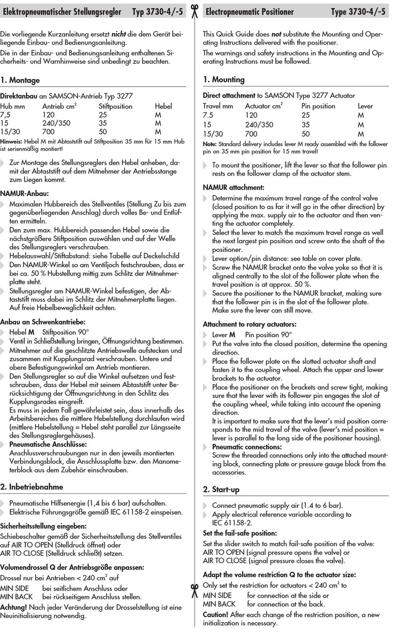
Direct attachment to SAMSON Type3277 Actuator
Travel [mm] Actuator [cm²] Lever Pin positi-
on
15 240, 350 M35
30 355, 700, 750 M50
To mount the positioner, lift the lever so that the follower pin rests
on the follower clamp of the actuator stem. Make sure the lever
can move freely.
NAMUR attachment
Travel [mm] Actuator [cm²] Travel Pin position
7.5 and 15 240, 350, 355, 700, 750 M35
30 355, 700, 750 M50
30 1000, 1400, 2800 L70
60 1000, 1400, 2800 L100
120 1400, 2800 XL 200
250 1400 XXL 300
Determine the travel range of the control valve (closed position to
as far it will go in the other direction) by applying the max. supply
air to the actuator and then venting the actuator completely.
Fasten the lever with follower pin onto the shaft of the positioner.

Fasten the NAMUR bracket onto the valve yoke so that it is aligned
centrally to the slot of the follower plate when the travel position
is at approx. 50%.

Fasten the positioner to the NAMUR bracket, making sure that the
follower pin is in the slot of the follower plate. Make sure the lever
can move freely.
Attachment to rotary actuators
Lever Pin position
M90°
Place the valve to the closed position.
Place the follower plate on the slotted actuator shaft and fasten it
to the coupling wheel. Mount the top and bottom brackets to the
actuator.
Fasten the positioner on the bracket. Make sure that:
–
The lever with its follower pin engages into the slot of the coupling
wheel, while taking into account the opening direction.
– The lever in the mid valve position is parallel to the long side
of the positioner housing.
2 Preparing start-up
1. Connect the supply air (2.5 to 10bar).
2. Connect the input signal (4 to 20mA).
Posicionador i/p TROVIS3793, TROVISSAFE3793
Esta guía básica no sustituye las instrucciones de montaje y servicio
que acompañan al equipo. Prestar atención a los avisos de seguridad
y advertencias incluidos en las instrucciones de montaje y servicio.
1 Montaje
Montaje integrado al accionamiento SAMSON Tipo3277
Carrera [mm] Accionamiento [cm²] Palanca Posición
del pin
15 240, 350 M35
30 355, 700, 750 M50
Para montar el posicionador levantar la palanca, para que el pin
apoye en el dispositivo de arrastre del vástago del accionamien-
to. Prestar atención a que la palanca se pueda mover libremente.
Montaje NAMUR
Carrera [mm] Accionamiento [cm²] Palanca Posición
del pin
7,5 y 15 240, 350, 355, 700, 750 M35
30 355, 700, 750 M50
30 1000, 1400, 2800 L70
60 1000, 1400, 2800 L100
120 1400, 2800 XL 200
250 1400 XXL 300
Determinar el margen de carrera de la válvula (desde posición
CERRADA hasta tope contrario) aireando y desaireando comple-
tamente el accionamiento.
Atornillar la palanca con el pin en el eje del posicionador.
Fijar el ángulo NAMUR en el puente de la válvula, de forma que
a aprox. al 50% de la carrera la ranura de la placa de arrastre
quede centrada.
Fijar el posicionador en el soporte angular NAMUR. El pin trans-
misor se tiene que alojar en la ranura de la placa de arrastre.
Prestar atención a que la palanca se pueda mover libremente.
Montaje en accionamiento rotativo
Palanca Posición del pin
M90°
Situar la válvula en su posición CERRADA.
Colocar el dispositivo de arrastre en la ranura del eje del accio-
namiento y atornillarlo junto con la rueda de acoplamiento.
Montar los ángulos de jación superior e inferior en el acciona-
miento.

Atornillar el posicionador en el soporte angular. Comprobar que:
– la palanca con su pin transmisor, teniendo en cuenta el senti-
do de apertura, encaja en la ranura de la rueda de acopla-
miento.
– la palanca en la posición de media carrera queda paralela
al lado largo de la carcasa del posicionador.
2 Preparación de la puesta en marcha
1. Conectar la energía auxiliar neumática (2,5 a 10bar).
2. Conectar la señal de entrada (4 a 20mA).
Edition April 2020 Quick Guide KA 8493 EN
3 Operation
Turn () the rotary pushbutton to select menu items, parameters,
or values. Press ( ) the button to conrm the setting.
 for 2s to go back one level.
Conguration must be enabled before changing parameters:
1.  to return to the main menu.
2.  until the 'User level' appears.
3.  and  until 'On-site: write' appears.
4.  to conrm.
Refer to associated mounting and operating instructions for details:
uEB8493 for TROVIS3793
uEB8493S for TROVISSAFE3793
Icon Meaning
Automatic mode
Manual mode
Fail-safe position
Open-loop control mode
Function mode
Failure
Function check
Out of specication
Maintenance demanded
OK
Icon Meaning
Conguration enabled
Write protection
Option module in slot C
Option module in slot D
Binary contact 1 active
Binary contact 2 active
Binary contact 3 active
5 Initialization
WARNING! Risk of crushing! During initialization, the valve moves
through its entire travel range/angle of rotation.
Note: Before initialization, mount the positioner on the control valve.
Connect the air supply and input signal.
For normal operation, simply start initialization by pressing the INIT
key (mode: MAX, closed position: ATO).
Use a thin, pointed object to press the initialization key: the posi-
tioner adapts itself automatically to the maximum travel range/
angle of rotation of the control valve.
Note: After changing the mounting situation, reset the positioner
before initialization (refer to mounting and operating instructions).
Tip: We recommend setting the software restriction in the positioner
for actuators with diaphragm areas ≤240cm² to 50% (start-up menu
7.21/ 7.2 2).
Refer to the mounting and operating instructions for other initializa-
tion modes and details.
4 Start-up
During the rst start-up, the wizard starts automatically:
1.  to determine the reading direction of the display.
2.  (2x) to conrm.
3.  to select language.
4.  (3x) to conrm. The positioner changes to the start screen.
5. Initialize the positioner (see section 5).
6 Display icons and their meaning
Edición Abril 2020 Guía básica KA 8493 ES
3 Operación
Girando () el selector se seleccionan puntos de menú, paráme-
tros y valores. Pulsando el botón ( ) se conrma la selección.
 durante 2s, para ir a un nivel de menú superior.
Para poder modicar parámetros, tiene que estar activa la congu-
ración:
1.  , para ir al menú principal.
2.  , hasta que aparece el "Nivel de usuario".
3.  y  hasta que aparece "Escritura local".
4.  , para conrmar.
Más detalles en las instrucciones de montaje y servicio correspondientes:
uEB8493 para TROVIS3793
uEB8493S para TROVISSAFE3793
SímboloSignicado
Modo automático
Modo manual
Posición de seguridad
Modo de lazo abierto
Modo función
Fallo
Control de función
Fuera de especicación
Mantenimiento
imprescindible
OK
SímboloSignicado
Desbloqueo para
conguración
Protección contra escritura
Módulo de opciones slot C
Módulo de opciones slot D
Contacto binario 1 activo
Contacto binario 2 activo
Contacto binario 3 activo
4 Puesta en marcha
En la primera puesta en marcha se inicia el asistente:
1. , para denir la dirección de lectura de la pantalla.
2.  (2x), para conrmar.
3. , para seleccionar el idioma del menú.
4.  (3x), para conrmar aparece la pantalla de inicio.
5. Inicializar el posicionador (ver capítulo 5).
5 Inicialización
¡ADVERTENCIA! ¡Riesgo de lesiones por aplastamiento! Durante la
inicialización la válvula recorre todo su margen de carrera/ángulo.
Info: antes de la inicialización montar el posicionador, conectar la
energía auxiliar neumática y conectar la señal de entrada.
Para una operación estándar, es suciente una inicialización rápida
mediante el pulsador de inicialización (Modo: MAX, dirección de
cierre: ATO).
Apretar el pulsador de inicialización con un objeto delgado: a
continuación el posicionador se adapta de forma automática al
margen de carrera/ángulo máximo de la válvula.
Info: después de modicar la posición de montaje se tendrá que res-
tablecer el posicionador y hacer una nueva inicialización (ver el EB).
Consejo: en accionamientos con supercie de membrana ≤240cm²
SAMSON recomienda ajustar la restricción por software del posicio-
nador al 50% (menú de puesta en marcha 7.21/7.22).
Otros modos de inicialización y más detalles ver EB.
6 Símbolos y su signicado

This manual suits for next models

1

Other Samson Valve Positioner manuals

Samson 4763 Service manual

Samson

Samson 4763 Service manual

Samson 4763 Service manual

Samson

Samson 4763 Service manual

Samson 3767 Setup guide

Samson

Samson 3767 Setup guide

Samson FOUNDATION 3730-5 Service manual

Samson

Samson FOUNDATION 3730-5 Service manual

Samson TROVIS 3730-1 Service manual

Samson

Samson TROVIS 3730-1 Service manual

Samson TROVIS 3730-3 Service manual

Samson

Samson TROVIS 3730-3 Service manual

Samson 3730-4 Service manual

Samson

Samson 3730-4 Service manual

Samson 3730 Series Service manual

Samson

Samson 3730 Series Service manual

Samson 3730-0 User manual

Samson

Samson 3730-0 User manual

Samson Type 3766 Service manual

Samson

Samson Type 3766 Service manual

Samson TROVIS 3730-1 User manual

Samson

Samson TROVIS 3730-1 User manual

Samson 3730-0 Service manual

Samson

Samson 3730-0 Service manual

Samson 3730 Series Service manual

Samson

Samson 3730 Series Service manual

Samson Type 3766 Service manual

Samson

Samson Type 3766 Service manual

Samson FOUNDATION 3730-5 Instruction sheet

Samson

Samson FOUNDATION 3730-5 Instruction sheet

Samson 3730-2 Service manual

Samson

Samson 3730-2 Service manual

Samson 4765 Service manual

Samson

Samson 4765 Service manual

Samson 3730-2 User manual

Samson

Samson 3730-2 User manual

Samson 3761 Service manual

Samson

Samson 3761 Service manual

Samson 3780 series Service manual

Samson

Samson 3780 series Service manual

Samson 3730-0 Service manual

Samson

Samson 3730-0 Service manual

Samson TROVIS 3731-3 Service manual

Samson

Samson TROVIS 3731-3 Service manual

Samson 3248-1 Service manual

Samson

Samson 3248-1 Service manual

Samson 373 Series User manual

Samson

Samson 373 Series User manual

Popular Valve Positioner manuals by other brands

Axis T99A11 installation guide

Axis

Axis T99A11 installation guide

Renishaw ACR2 installation guide

Renishaw

Renishaw ACR2 installation guide

Ytc YT-1000L installation manual

Ytc

Ytc YT-1000L installation manual

Flowserve Logix 520MD+ User instructions

Flowserve

Flowserve Logix 520MD+ User instructions

Genebre 5951 00 Installation, operation and maintenance manual

Genebre

Genebre 5951 00 Installation, operation and maintenance manual

Novatel SPAN-IGM user manual

Novatel

Novatel SPAN-IGM user manual

Avid Technology SMARTCAL Installation and operation manual

Avid Technology

Avid Technology SMARTCAL Installation and operation manual

Waycon SX300 Series manual

Waycon

Waycon SX300 Series manual

Westlock ICoT PA Installation & operating manual

Westlock

Westlock ICoT PA Installation & operating manual

Pepperl+Fuchs PMI14V-F112-IO Series manual

Pepperl+Fuchs

Pepperl+Fuchs PMI14V-F112-IO Series manual

Burkert 1067 manual

Burkert

Burkert 1067 manual

Burkert 8791 REV.2 quick start

Burkert

Burkert 8791 REV.2 quick start

STI SA/CL instruction manual

STI

STI SA/CL instruction manual

Power-Genex SS2L Series manual

Power-Genex

Power-Genex SS2L Series manual

Burkert 8791 operating instructions

Burkert

Burkert 8791 operating instructions

Keysight Technologies N2784A user guide

Keysight Technologies

Keysight Technologies N2784A user guide

halstrup-walcher PS-3 Series Original instruction manual

halstrup-walcher

halstrup-walcher PS-3 Series Original instruction manual

Westlock Controls Corporation TECH-385Q operating manual

Westlock Controls Corporation

Westlock Controls Corporation TECH-385Q operating manual

manuals.online logo
manuals.online logoBrands
  • About & Mission
  • Contact us
  • Privacy Policy
  • Terms and Conditions

Copyright 2025 Manuals.Online. All Rights Reserved.